Steel Joist Manual
Steel Joist Manual
Steel Joist Manual

Create successful ePaper yourself
Turn your PDF publications into a flip-book with our unique Google optimized e-Paper software.
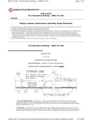
FIRE-RESISTANCE RATINGS<br />
WITH STEEL JOISTS<br />
The Underwriters Laboratories (U.L.) Fire Resistance<br />
Directory lists hundreds of assemblies and their fire resistance<br />
ratings. The Specifying Professional can choose<br />
between numerous Floor-Ceiling and Roof-Ceiling assemblies<br />
that include steel joists and <strong>Joist</strong> Girders.<br />
As a convenience, a selected number of assemblies are<br />
listed on the following pages. In addition, the <strong>Steel</strong> <strong>Joist</strong><br />
Institute’s Technical Digest #10 “Design of Fire Resistive<br />
Assemblies with <strong>Steel</strong> <strong>Joist</strong>s” has a complete listing of steel<br />
joist assemblies and additional information about fire ratings.<br />
However, the listing that follows and the Technical<br />
Digest are intended as a guide only, and the Specifying<br />
Professional must refer to the current U.L. Fire Resistance<br />
Directory for complete design requirements.<br />
Hundreds of fire tests on steel joist-supported assemblies<br />
have been conducted at nationally recognized testing laboratories<br />
in accordance with ASTM Standard E119, ANSI<br />
A2.1/UL 263, and NFPA 251. Because of practical loading<br />
restrictions and limitations of furnace dimensions, the vast<br />
majority of these tests were run using lightweight joists –<br />
normally from 8 inches to 14 inches (203 mm to 356 mm)<br />
deep. This practice was advantageous in that it established<br />
the minimum acceptable joists at the shallow and lightweight<br />
end of the joist load tables. This also resulted in a specified<br />
minimum joist designation being listed in the U.L. Fire<br />
Resistance Assembly, which is the joist that combines the<br />
required minimum depth and minimum weight per foot.<br />
<strong>Joist</strong>s of the same series which equal or exceed the specified<br />
minimum joist depth and joist weight per foot may be<br />
used provided the accessories are compatible. The dimension<br />
from the bottom chord of the joists to the ceiling,<br />
whether given or calculated, is a minimum.<br />
Where a U.L. Fire Resistance Assembly is being utilized, the<br />
Specifying Professional shall indicate the assembly number<br />
being used on the structural contract drawings. In addition,<br />
the Specifying Professional shall consider the following, as<br />
applicable:<br />
• <strong>Joist</strong> designations specified on the structural contract<br />
drawings shall not be less than the minimum size for<br />
that assembly. The assembly may also require a minimum<br />
bridging size that may be larger than required by<br />
the SJI Specifications for the particular designation and<br />
joist spacing.<br />
• Some assemblies stipulate minimum size materials or<br />
minimum cross sectional areas for individual joist and<br />
<strong>Joist</strong> Girder components. It is the responsibility of the<br />
Specifying Professional to show all special requirements<br />
on the contract drawings.<br />
• Note that the maximum joist spacing shown for Floor-<br />
Ceiling Assemblies may be increased from the spacing<br />
listed in the U.L. Fire Resistance Directory to a maximum<br />
of 48 inches on center, provided the floor slab<br />
meets the structural requirements and the spacing of<br />
hanger wires supporting the ceiling is not increased.<br />
• Some assemblies stipulate an allowable maximum joist<br />
design stress level less than the 30 ksi (207 MPa) used<br />
in the joist and <strong>Joist</strong> Girder Specifications. It is the<br />
responsibility of the Specifying Professional to apply the<br />
proper stress level reductions (when applicable) when<br />
selecting joists and/or <strong>Joist</strong> Girders. This is accomplished<br />
by prorating the joist and/or <strong>Joist</strong> Girder capacities.<br />
To adjust the stress level of joists or <strong>Joist</strong> Girders,<br />
multiply the design load by the ratio of the joist design<br />
stress to the required maximum [e.g. 30/26 (207/179),<br />
30/24 (207/165), 30/22 (207/152)], and then using this<br />
increased load, select a joist or <strong>Joist</strong> Girder from the load<br />
and/or weight tables.<br />
• Some U.L. Roof-Ceiling Assemblies using direct applied<br />
protection limit the spacing of the joists for certain types<br />
and gages of metal decking – refer to the U.L. Fire<br />
Resistance Directory for this information.<br />
• Where fire protective materials are to be applied directly<br />
to the steel joists or <strong>Joist</strong> Girders, it is often desired to<br />
have the joist furnished as unpainted. The Specifying<br />
Professional should indicate on the structural contract<br />
drawings if the joists or <strong>Joist</strong> Girders are to be painted<br />
or not.<br />
• Certain older U.L. fire rated assemblies may refer to<br />
joist series that predate the K-Series joists. Where one<br />
of these assemblies is selected, refer to the U.L Fire<br />
Resistance Directory for special provisions for substituting<br />
a K-Series joist in lieu of an S-, J-, and/or H-Series<br />
joist.<br />
113