Steel Joist Manual
Steel Joist Manual
Steel Joist Manual
You also want an ePaper? Increase the reach of your titles
YUMPU automatically turns print PDFs into web optimized ePapers that Google loves.
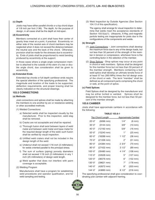
LONGSPAN AND DEEP LONGSPAN STEEL JOISTS, LH- AND DLH-SERIES<br />
(c) Depth<br />
<strong>Joist</strong>s may have either parallel chords or a top chord slope<br />
of 1/8 inch per foot (1:96). The depth, for the purpose of<br />
design, in all cases shall be the depth at mid-span.<br />
(d) Eccentricity<br />
Members connected at a joint shall have their center of<br />
gravity lines meet at a point, if practical. Eccentricity on<br />
either side of the neutral axis of chord members may be<br />
neglected when it does not exceed the distance between<br />
the neutral axis and the back of the chord. Otherwise,<br />
provision shall be made for the stresses due to eccentricity.<br />
Ends of joists shall be proportioned to resist bending<br />
produced by eccentricity at the support.<br />
In those cases where a single angle compression member<br />
is attached to the outside of the stem of a tee or double<br />
angle chord, due consideration shall be given to<br />
eccentricity.<br />
(e) Extended Ends<br />
Extended top chords or full depth cantilever ends require<br />
the special attention of the specifying professional. The<br />
magnitude and location of the loads to be supported,<br />
deflection requirements, and proper bracing shall be<br />
clearly indicated on the structural drawings.<br />
103.5 CONNECTIONS<br />
(a) Methods<br />
<strong>Joist</strong> connections and splices shall be made by attaching<br />
the members to one another by arc or resistance welding<br />
or other accredited methods.<br />
(1) Welded Connections<br />
a) Selected welds shall be inspected visually by the<br />
manufacturer. Prior to this inspection, weld slag<br />
shall be removed.<br />
b) Cracks are not acceptable and shall be repaired.<br />
c) Thorough fusion shall exist between layers of weld<br />
metal and between weld metal and base metal for<br />
the required design length of the weld; such fusion<br />
shall be verified by visual inspection.<br />
d) Unfilled weld craters shall not be included in the<br />
design length of the weld.<br />
e) Undercut shall not exceed 1/16 inch (2 millimeters)<br />
for welds oriented parallel to the principal stress.<br />
f) The sum of surface (piping) porosity diameters<br />
shall not exceed 1/16 inch (2 millimeters) in any 1<br />
inch (25 millimeters) of design weld length.<br />
g) Weld spatter that does not interfere with paint<br />
coverage is acceptable.<br />
(2) Welding Program<br />
Manufacturers shall have a program for establishing<br />
weld procedures and operator qualification, and for<br />
weld sampling and testing.<br />
(3) Weld Inspection by Outside Agencies (See Section<br />
104.13 of this specification).<br />
The agency shall arrange for visual inspection to determine<br />
that welds meet the acceptance standards of<br />
Section 103.5(a)(1). Ultrasonic, X-Ray, and magnetic<br />
particle testing are inappropriate for joists due to the<br />
configurations of the components and welds.<br />
(b) Strength<br />
(1) Joint Connections – Joint connections shall develop<br />
the maximum force due to any of the design loads, but<br />
not less than 50 percent of the strength of the member<br />
in tension or compression, whichever force is the<br />
controlling factor in the selection of the member.<br />
(2) Shop Splices - Shop splices may occur at any point<br />
in chord or web members. Splices shall be designed<br />
for the member force but not less than 50 percent of<br />
the member strength. Members containing a butt<br />
weld splice shall develop an ultimate tensile force of<br />
at least 57 ksi (393 MPa) times the full design area<br />
of the chord or web. The term “member” shall be<br />
defined as all component parts comprising the chord<br />
or web, at the point of splice.<br />
(c) Field Splices<br />
Field Splices shall be designed by the manufacturer and<br />
may be either bolted or welded. Splices shall be<br />
designed for the member force, but not less than 50 percent<br />
of the member strength.<br />
103.6 CAMBER<br />
<strong>Joist</strong>s shall have approximate cambers in accordance with<br />
the following:<br />
TABLE 103.6-1<br />
Top Chord Length Approximate Camber<br />
20'-0" (6096 mm) 1/4" (6 mm)<br />
30'-0" (9144 mm) 3/8" (10 mm)<br />
40'-0" (12192 mm) 5/8" (16 mm)<br />
50'-0" (15240 mm) 1" (25 mm)<br />
60'-0" (18288 mm) 1 1/2" (38 mm)<br />
70'-0" (21336 mm) 2" (51 mm)<br />
80'-0" (24384 mm) 2 3/4" (70 mm)<br />
90'-0" (27432 mm) 3 1/2" (89 mm)<br />
100'-0" (30480 mm) 4 1/4" (108 mm)<br />
110'-0" (33528 mm) 5" (127 mm)<br />
120'-0" (36576 mm) 6" (152 mm)<br />
130'-0" (39621 mm) 7" (178 mm)<br />
140'-0" (42672 mm) 8" (203 mm)<br />
144'-0" (43890 mm) 8 1/2" (216 mm)<br />
The specifying professional shall give consideration to coordinating<br />
joist camber with adjacent framing.<br />
56


