Steel Joist Manual
Steel Joist Manual
Steel Joist Manual

Create successful ePaper yourself
Turn your PDF publications into a flip-book with our unique Google optimized e-Paper software.
CODE OF STANDARD PRACTICE FOR STEEL JOISTS AND JOIST GIRDERS<br />
Option 2: Select a KCS joist using moment and end<br />
reaction. This option works well for concentrated loads<br />
for which exact locations are not known or for multiple<br />
loading. See examples and limitations on the pages<br />
accompanying the KCS <strong>Joist</strong> Load Tables.<br />
a) Determine the maximum moment<br />
b) Determine the maximum end reaction (shear)<br />
c) Select the required KCS joist that provides the required<br />
moment and end reaction (shear).<br />
Option 3: Specify a SPECIAL joist with load diagrams.<br />
This option is preferred when the joist includes loading<br />
that cannot clearly be denoted on the structural drawings.<br />
a) Provide a load diagram to clearly define ALL loads<br />
b) Place the designation ( i.e. 18K SP or 18LH SP )<br />
under the load diagram with the following note:<br />
“<strong>Joist</strong> manufacturer to design joist to support loads<br />
as shown above”.<br />
CAUTION: The specifying professional shall compare<br />
the equivalent uniform loads derived from the maximum<br />
moment and shear to the uniform loads tabulated<br />
in the K-Series Load Table. An equivalent unfactored<br />
uniform load in excess of 550 plf (8020 N/m) or a maximum<br />
unfactored end reaction exceeding 9200 lbs (40.9<br />
kN) indicates that the specifying professional shall<br />
consider using additional joists to reduce the loading or<br />
use an LH-Series <strong>Joist</strong> and make provisions for 5 inch<br />
(127 mm) deep bearing seats.<br />
SPECIAL LOADING : Please note the load combinations<br />
shown are for referenced examples only and it is not to<br />
be presumed that the joist designer is responsible for<br />
the applicable building code load combinations. If the<br />
loading criteria are too complex to adequately communicate<br />
in a simple load diagram, then the specifying professional<br />
shall provide a load schedule showing the<br />
specified design loads, load categories, and required<br />
load combinations with applicable load factors.<br />
ASD EXAMPLE:<br />
U.S. CUSTOMARY UNITS AND (METRIC UNITS)<br />
Load diagram per ASCE 7 2.4.1(3) D + S<br />
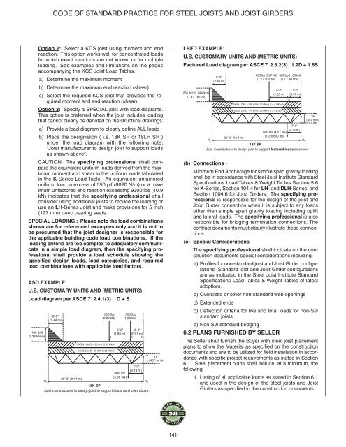
LRFD EXAMPLE:<br />
U.S. CUSTOMARY UNITS AND (METRIC UNITS)<br />
Factored Load diagram per ASCE 7 2.3.2(3) 1.2D + 1.6S<br />
256 lb/ft (3.74 kN/m)<br />
(1.6 x 160 plf)<br />
RL<br />
8'-0"<br />
(2.44 m)<br />
SNOW LOAD – 288 lb/ft (4.21 kN/m) (1.6 x 180 plf)<br />
DEAD LOAD – 72 lb/ft (1.06 kN/m) (1.2 x 60 plf)<br />
30'-0" (9.14 m)<br />
600 lbs (2.67 kN)<br />
(1.2 x 500 lbs)<br />
6'-0"<br />
(1.83 m)<br />
960 lbs (4.27 kN)<br />
(1.2 x 800 lbs)<br />
360 lbs (1.60 kN)<br />
(1.2 x 300 lbs)<br />
3'-0"<br />
(0.91 m)<br />
7'-0"<br />
(2.13 m)<br />
18K SP<br />
<strong>Joist</strong> manufacturer to design joist to support factored loads as shown.<br />
(b) Connections -<br />
Minimum End Anchorage for simple span gravity loading<br />
shall be in accordance with <strong>Steel</strong> <strong>Joist</strong> Institute Standard<br />
Specifications Load Tables & Weight Tables Section 5.6<br />
for K-Series, Section 104.4 for LH- and DLH-Series, and<br />
Section 1004.6 for <strong>Joist</strong> Girders. The specifying professional<br />
is responsible for the design of the joist and<br />
<strong>Joist</strong> Girder connection when it is subject to any loads<br />
other than simple span gravity loading including uplift<br />
and lateral loads. The specifying professional is also<br />
responsible for bridging termination connections. The<br />
contract documents must clearly illustrate these connections.<br />
(c) Special Considerations<br />
The specifying professional shall indicate on the construction<br />
documents special considerations including:<br />
a) Profiles for non-standard joist and <strong>Joist</strong> Girder configurations<br />
(Standard joist and <strong>Joist</strong> Girder configurations<br />
are as indicated in the <strong>Steel</strong> <strong>Joist</strong> Institute Standard<br />
Specifications Load Tables & Weight Tables of latest<br />
adoption).<br />
b) Oversized or other non-standard web openings<br />
c) Extended ends<br />
d) Deflection criteria for live and total loads for non-SJI<br />
standard joists<br />
e) Non-SJI standard bridging<br />
6.2 PLANS FURNISHED BY SELLER<br />
The Seller shall furnish the Buyer with steel joist placement<br />
plans to show the Material as specified on the construction<br />
documents and are to be utilized for field installation in accordance<br />
with specific project requirements as stated in Section<br />
6.1. <strong>Steel</strong> placement plans shall include, at a minimum, the<br />
following:<br />
1. Listing of all applicable loads as stated in Section 6.1<br />
and used in the design of the steel joists and <strong>Joist</strong><br />
Girders as specified in the construction documents.<br />
RR<br />
18"<br />
(457 mm)<br />
141