American Commander Cartridge - Rick English - Swimming Pool ...
American Commander Cartridge - Rick English - Swimming Pool ...
American Commander Cartridge - Rick English - Swimming Pool ...

Create successful ePaper yourself
Turn your PDF publications into a flip-book with our unique Google optimized e-Paper software.
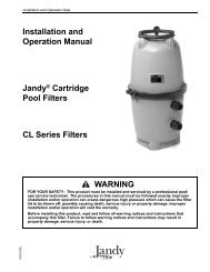
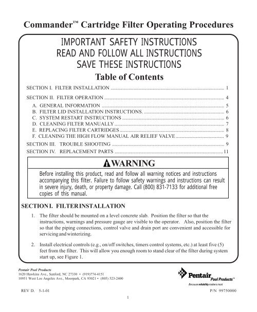
<strong>Commander</strong> <strong>Cartridge</strong> Filter Operating Procedures<br />
IMPORTANT SAFETY INSTRUCTIONS<br />
READ AND FOLLOW ALL INSTRUCTIONS<br />
SAVE THESE INSTRUCTIONS<br />
Table of Contents<br />
SECTION I. FILTER INSTALLATION ......................................................................................... 1<br />
SECTION II. FILTER OPERATION .............................................................................................. 4<br />
A. GENERAL INFORMATION ................................................................................................ 5<br />
B. FILTER LID INSTALLATION INSTRUCTIONS. ............................................................... 6<br />
C. SYSTEM RESTART INSTRUCTIONS ................................................................................ 6<br />
D. CLEANING FILTER MANUALLY ...................................................................................... 7<br />
E. REPLACING FILTER CARTRIDGES.................................................................................. 8<br />
F. CLEANING THE HIGH FLOW MANUAL AIR RELIEF VALVE...................................... 9<br />
SECTION III. TROUBLE SHOOTING ........................................................................................ 9<br />
SECTION IV. REPLACEMENT PARTS .....................................................................................11<br />
WARNING<br />
Before installing this product, read and follow all warning notices and instructions<br />
accompanying this filter. Failure to follow safety warnings and instructions can result<br />
in severe injury, death, or property damage. Call (800) 831-7133 for additional free<br />
copies of this manual.<br />
SECTION I. FILTER INSTALLATION<br />
1. The filter should be mounted on a level concrete slab. Position the filter so that the<br />
instructions, warnings and pressure gauge are visible to the operator. Also, position the filter<br />
so that the piping connections, control valve and drain port are convenient and accessible for<br />
servicing and winterizing.<br />
2. Install electrical controls (e.g., on/off switches, timers control systems, etc.) at least five (5)<br />
feet from the filter. This will allow you enough room to stand clear of the filter during system<br />
start up, see Figure 1.<br />
Pentair <strong>Pool</strong> Products<br />
1620 Hawkins Ave., Sanford, NC 27330 • (919)774-4151<br />
10951 West Los Angeles Ave., Moorpark, CA 93021 • (805) 523-2400<br />
REV D. 5-1-01 P/N 99750000<br />
1
3. Provide sufficient space above the filter to remove the filter lid and cartridge for cleaning and<br />
servicing. This distance will vary with the model of filter you are using. See Table 1 for the<br />
required vertical clearance above the filter.<br />
TABLE 1<br />
Model Size Vertical Clearance Req.<br />
56109000 25 sq. ft. 24 in.<br />
56159000 35 sq. ft. 24 in.<br />
56209000 50 sq. ft. 44 in.<br />
56359000 75 sq. ft. 44 in.<br />
56759000 100 sq. ft. 64 in.<br />
56760000 150 sq. ft. 74 in.<br />
WARNING<br />
Risk of electrical shock or electrocution. Position the filter and High Flow Air Relief<br />
Valve to safely direct water drainage and purged air or water. Water discharged from<br />
an improperly positioned filter or valve can create an electrical hazard that can cause<br />
severe personal injury as well as damage property.<br />
4. When installing the High Flow Manual Air Relief<br />
Valve position the filter to safely direct water<br />
drainage. Rotate the High Flow Manual Air Relief<br />
Valve to safely direct purged air or water. Water<br />
discharged from an improperly positioned filter or<br />
valve can create an electrical hazard as well as<br />
damage property.<br />
5. Always follow procedures published by solvent<br />
cement manufacturers for preparation and gluing of<br />
pipe to the filter.<br />
NOTE<br />
On threaded valve connections use only Teflon tape,<br />
100% Teflon tape, 100% Teflon paste, or Permatex #2<br />
to seal the threads.<br />
Figure 1.<br />
P/N 99750000 REV D. 5-1-01<br />
2
6. THE FILTER BASE IS ABS MATERIAL. WHEN PVC PIPE IS BEING USED THE CORRECT ABS<br />
TO PVC SOLVENT PIPE CEMENT MUST BE USED. WE RECOMMEND WELD-ON #793 OR<br />
EQUIVALENT.<br />
7. An additional inlet port is provided in the base for easier installation. Select the desired inlet port<br />
and plug the other inlet port with 1½ in. plug provided, (item #13).<br />
a. If your filter has slip ports use item 13, 1½ in. ABS slip plug. Use ABS to ABS solvent, we<br />
recommend WELD-ON #771 or equivalent. A ½ in. plug (item #14) is also provided for use as<br />
a drain plug.<br />
b. If your filter has threaded ports use item 13, 1½ in. threaded plug. Use only teflon tape, 100%<br />
teflon paste, or Permatex #2 to seal the threads. Use of other materials could damage the<br />
equipment.<br />
8. The 25, and 50 sq. ft. models are equipped with Turbo-Flo by-pass valve. If by-pass is not desired,<br />
plug off with item #16 using WELD-ON #771 or equivalent.<br />
9. The maximum working pressure of this filter is 50 p.s.i. Never subject this filter to pressure in<br />
excess of this amount, even when conducting hydrostatic pressure tests. Pressures above 50 p.s.i.<br />
can cause the lid to be blown off, which can result in severe injury, death or property damage.<br />
When performing hydrostatic pressure tests or when testing for external leaks of the completed<br />
filtration and plumbing system, insure that the Maximum Pressure that the filtration<br />
system will be subjected to DOES NOT EXCEED THE MAXIMUM WORKING PRESSURE OF<br />
ANY OF THE COMPONENTS CONTAINED WITHIN THE SYSTEM. In most cases, the<br />
maximum pressure will be stated on each component of the system.<br />
If doubt exists as to the pressure to which the system will be subjected, install an ASME<br />
approved automatic Pressure Relief or Pressure Regulator in the circulation system for the<br />
lowest working pressure of any of the components in the system.<br />
REV D. 5-1-01 P/N 99750000<br />
3
SECTION II. FILTER OPERATION<br />
WARNING<br />
THIS FILTER OPERATES UNDER HIGH PRESSURE. WHEN ANY PART OF THE<br />
CIRCULATING SYSTEM (e.g., FILTER LID, PUMP, FILTER, VALVES, ETC.) IS<br />
SERVICED, AIR CAN ENTER THE SYSTEM AND BECOME PRESSURIZED.<br />
PRESSURIZED AIR CAN CAUSE THE LID TO BLOW OFF WHICH CAN RESULT IN<br />
SEVERE INJURY, DEATH, OR PROPERTY DAMAGE. TO AVOID THIS POTENTIAL<br />
HAZARD, FOLLOW THESE INSTRUCTIONS.<br />
1. BEFORE REPOSITIONING VALVES AND BEFORE BEGINNING THE ASSEMBLY,<br />
DISASSEMBLY, OR ADJUSTMENT OF THE LID OR ANY OTHER SERVICE OF<br />
THE CIRCULATING SYSTEM: (A) TURN THE PUMP OFF AND SHUT OFF ANY<br />
AUTOMATIC CONTROLS TO ASSURE THE SYSTEM IS NOT INADVERTENTLY<br />
STARTED DURING THE SERVICING. (B) OPEN HIGH FLOW MANUAL AIR<br />
RELIEF VALVE, AND (C) WAIT UNTIL ALL PRESSURE IS RELIEVED -PRESSURE<br />
GAUGE MUST READ ZERO (0).<br />
2. WHENEVER INSTALLING THE FILTER LID, FOLLOW THE FILTER LID<br />
INSTALLATION INSTRUCTIONS EXACTLY.<br />
3. ONCE SERVICE ON THE CIRCULATING SYSTEM IS COMPLETE, FOLLOW<br />
SYSTEM RESTART INSTRUCTIONS EXACTLY.<br />
4. MAINTAIN CIRCULATION SYSTEM PROPERLY. REPLACE WORN OR<br />
DAMAGED PARTS IMMEDIATELY (e.g., lid, knob, pressure gauge, relief valve,<br />
O-rings, etc.)<br />
5. BE SURE THAT THE FILTER IS PROPERLY MOUNTED AND POSITIONED<br />
ACCORDING TO INSTRUCTIONS PROVIDED.<br />
P/N 99750000 REV D. 5-1-01<br />
4
A. GENERAL INFORMATION<br />
1. This filter operates under pressure. When assembled properly and operated without air in the<br />
water system, this filter will operate in a safe manner.<br />
2. The maximum working pressure of this filter is 50 p.s.i. Never subject this filter to pressure in<br />
excess of this amount - even when conducting hydrostatic pressure tests. Pressures above 50<br />
p.s.i. can cause the lid to be blown off, which can result in severe injury, death or property damage.<br />
When performing hydrostatic pressure tests or when testing for external leaks of the<br />
completed filtration and plumbing system, insure that the Maximum Pressure that the filtration<br />
system will be subjected to DOES NOT EXCEED THE MAXIMUM WORKING PRESSURE OF<br />
ANY OF THE COMPONENTS CONTAINED WITHIN THE SYSTEM. In most cases, the<br />
maximum pressure will be stated on each component of the system.<br />
If doubt exists as to the pressure to which the system will be subjected, install an ASME<br />
approved automatic Pressure Relief or Pressure Regulator in the circulation system for the<br />
lowest working pressure of any of the components in the system.<br />
3. The pressure gauge is the primary indicator of how the filter is operating. Maintain your pressure<br />
gauge in good working order.<br />
WARNING<br />
Your filter is a piece of machinery, do not tamper with it, attempt to disassemble it or<br />
otherwise adjust it unless you fully understand it's operation. Serious injury or death<br />
can occur if the equipment is improperly handled. Consult a pool service professional<br />
for maintenance and service assistance.<br />
4. Clean your filter when pressure reads between 8-10 p.s.i. higher than the original starting pressure.<br />
Your filter pressure reading will increase as it removes dirt from your pool. However, this buildup<br />
of pressure will vary due to different bathing loads, temperature, weather conditions, etc.<br />
a. MY ORIGINAL STARTING PRESSURE IS ___________ p.s.i. (pounds per square inch). I<br />
SHOULD CLEAN THE FILTER CARTRIDGES AT __________ p.s.i.<br />
NOTE<br />
Whenever the cartridge filter is being used for the first time on a new swimming pool, or when<br />
extra water clarity is desired, introduce into the system a one (1) pound coffee can (½ pound of<br />
diatomaceous earth) for every 100 square feet of filter area. Mix the diatomite with water and<br />
pour it into the skimmer after the pump is primed and the system is operating.<br />
REV D. 5-1-01 P/N 99750000<br />
5
B. FILTER LID INSTALLATION INSTRUCTIONS.<br />
1. Ensure that the O-ring is in position in the lid then locate lid on rod, centering lid in cartridge<br />
opening.<br />
2. Secure the entire assembly by using the top knob to firmly seal the lid against the O-ring and the<br />
body.<br />
3. Before starting pump open the High Flow Manual Air Relief Valve on the filter lid.<br />
4. Stand clear of the filter tank, then start the pump.<br />
5. Close the High Flow Manual Air Relief Valve when a steady stream of water is flowing. This<br />
indicates that all air is bled from tank.<br />
C. SYSTEM RESTART INSTRUCTIONS<br />
WARNING<br />
THIS FILTER OPERATES UNDER HIGH PRESSURE. WHEN ANY PART OF THE<br />
CIRCULATING SYSTEM (e.g., FILTER LID, PUMP, FILTER, VALVES, ETC.) IS<br />
SERVICED, AIR CAN ENTER THE SYSTEM AND BECOME PRESSURIZED.<br />
PRESSURIZED AIR CAN CAUSE THE LID TO BE BLOWN OFF WHICH CAN RESULT<br />
IN SEVERE INJURY, DEATH, OR PROPERTY DAMAGE. TO AVOID THIS<br />
POTENTIAL HAZARD, FOLLOW THESE INSTRUCTIONS.<br />
1. Open the High Flow Air Relief Valve until it snaps into the full open position (this only requires a<br />
quarter turn counterclockwise). Opening this valve rapidly releases air trapped in the filter.<br />
2. Stand clear of the filter tank, then start the pump.<br />
3. Close the High Flow Air Relief Valve after a steady stream of water appears.<br />
4. The system is not working properly if either of the following conditions occur.<br />
a. A solid stream of water does not appear within 30 seconds, after the pump's inlet basket fills<br />
with water.<br />
b. The pressure gauge indicates pressure before water outflow appears.<br />
If either condition exists, shut off the pump immediately, open valves in the water return line to<br />
relieve pressure, and clean the High Flow Manual Air Relief Valve, see Section F, Cleaning the<br />
High Flow Air Relief Valve. If the problem persists, call 1-800-831-7133 for assistance.<br />
P/N 99750000 REV D. 5-1-01<br />
6
D. CLEANING FILTER MANUALLY<br />
1. Turn the pump off, shut off any automatic controls to ensure that the system is not inadvertently<br />
started during servicing.<br />
2. Open the filter High Flow Air Relief Valve (and, the waste drain valve, or plug, if your system has<br />
one).<br />
3. Remove hair and lint strainer pot lid and clean basket. Replace basket and secure lid.<br />
4. Unscrew large center knob (item 1) and remove top lid assembly (item 4).<br />
5. Remove drain plug in base of the filter (item 11) to allow excess water and residue to drain from the<br />
tank.<br />
6. Remove cartridge or cartridges.<br />
CAUTION<br />
The following information should be read carefully since it outlines the proper manner of care and<br />
operation for your filter system. As a result of following these instructions and taking the necessary<br />
preventative care, you can expect maximum efficiency and life from your filtration system.<br />
7. Using a garden hose without a nozzle, direct water spray at cartridges to dislodge and wash away<br />
accumulated foreign matter. Flush each cartridge inside-out.<br />
CAUTION<br />
Please heed all manufacturers' posted instructions, warnings and cautions when<br />
using Baquacil® or Baqua Clean®.<br />
REV D. 5-1-01 P/N 99750000<br />
7
NOTE<br />
Special care must be taken when cleaning filter cartridges used in a swimming pool or spa using<br />
Baquacil as a sanitizer. Because of the way Baquacil works, the filter element must be cleaned<br />
more thoroughly and more frequently than in a chlorine system, If extreme care is not taken to<br />
completely remove all residue from the filter media a buildup will occur. This buildup will significantly<br />
shorten the life of the filter element.<br />
Baquacil is a mild coagulant which combines bacterial cells as well as other small particles<br />
contributed by the environment, bathers, etc. into particles large enough to be trapped by the<br />
filter. In comparison with all other trapped contaminants in a typical pool or spa the amount of<br />
bacterial cells that are deposited on the filter is minimal. The resulting deposit is a gray sticky film<br />
which can only be removed with Baqua Clean. If TSP or any TSP type cleaner is used prior to<br />
stripping the film, the cleaner and the fray film will combine to form a gum-like substance. Once<br />
this occurs, the substance cannot be removed from the media and the filter cartridge must be<br />
replaced.<br />
8. Direct water spray to wash out the inside of the tank body. Water and debris will drain out through<br />
the open drain port.<br />
9. Place cartridge or cartridges into the tank and press firmly into filter base. Ensure that the internal<br />
air bleed assembly is in place and not damaged.<br />
10. Replace tank drain plug (item 11) in base of filter. Put filter lid (item 3) in place so that center rod<br />
protrudes.<br />
11. Secure the entire assembly by using the top knob (item 1) to firmly seal the lid against the O-ring<br />
and the body.<br />
E. REPLACING FILTER CARTRIDGES<br />
Filter <strong>Cartridge</strong> life will vary with pool conditions such as<br />
bather load, wind, dust, etc. You can expect an average<br />
cartridge life of 3 years under normal conditions.<br />
1. To replace cartridges follow steps in section D, Cleaning<br />
Filter, eliminating step D.7<br />
NOTE<br />
Anytime the filter tank is opened and/or element assembly is<br />
removed, be sure to generously coat the filter O-ring with<br />
silicone lubricant before reassembling the unit. Do not use<br />
petroleum base lubricants because they have a deteriorating<br />
effect on rubber. Figure 2.<br />
P/N 99750000 REV D. 5-1-01<br />
8
F. CLEANING THE HIGH FLOW MANUAL AIR RELIEF VALVE<br />
1. Turn the pump off and shut off any automatic controls to ensure that the system is not<br />
inadvertently started during servicing.<br />
2. OPEN THE HIGH FLOW MANUAL AIR RELIEF VALVE UNTIL IT SNAPS INTO THE FULL<br />
OPEN POSITION, THEN WAIT UNTIL ALL PRESSURE IS RELIEVED.<br />
3. With the relief valve attached to the filter tank, pull out the locking tabs and remove the valve stem<br />
and cover assembly with a counterclockwise and lifting motion, see Figure 2.<br />
4. Clean debris from the valve stem and body. Verify that the filter tank's air passage is open by<br />
inserting a 5/16" drill bit through the valve body. Verify that the O-rings are in good condition,<br />
properly positioned, and lubricated with a silicone base lubricant.<br />
5. Reinstall the valve stem and cover assembly with a downward and clockwise motion until it snaps<br />
into position.<br />
SECTION III. TROUBLE SHOOTING<br />
A. Air entering your filter is dangerous and can cause the lid to blow off. Correct any conditions in your<br />
filtration system that allow air to enter the system.<br />
1. Some common ways to identify air entering the system:<br />
a. Low water level in pool or spa - skimmer is starving for water with pump running. Add water<br />
to pool or spa.<br />
b. Air bubbles or low water level in pump hair and lint pot are caused by; low water level,<br />
clogged skimmer basket, split suction cleaner hose, leak in pump hair and lint pot lid, or leak in<br />
pump suction line.<br />
c. Air bubbles coming out of water return lines into pool or spa with pump running, see items 1.a<br />
and 1.b of this section.<br />
d. Air is discharged from the High Flow Manual Air Relief Valve on top of the filter when the<br />
valve is opened with the pump running, see items 1.a and 1.b of this section, above.<br />
e. Before you assemble the lid, ensure that the internal air bleed assembly is in place and not<br />
clogged or damaged.<br />
B. Until the water initially put into the pool has been completely filtered, short filter cycles in between<br />
cleanings are normal. In most cases pool owners are dismayed by the undesirable color and appearance of<br />
water in a newly filled pool. Plaster dust can be responsible for short filter cycles, requiring frequent<br />
cleaning.<br />
REV D. 5-1-01 P/N 99750000<br />
9
C. If pressure drops on gauge, check skimmer basket and pump basket first for debris. If the baskets are<br />
clean, shut off power to pump and turn off any automatic controls. Then turn motor shaft with your<br />
fingers. If it turns freely then the pump must be disassembled and the impeller checked to see if it is<br />
clogged. If it is not frozen or clogged then there is an obstruction in the line between the pool and the<br />
pump.<br />
D. The pressure gauge is an important part of the filter system. It is your primary indicator of how the<br />
system is operating. Maintain your pressure gauge in good working order. Check the operation of<br />
your pressure gauge in the following manner:<br />
1. The pressure gauge should go to zero (0) when the system is turned off and pressure is relieved.<br />
2. The pressure gauge should indicate pressure when the system is operating.<br />
3. The pressure gauge should be readable and not damaged in any way.<br />
4. Replace the pressure gauge if it is not meeting the requirements of items D.1 through D.2 of this<br />
section, above.<br />
P/N 99750000 REV D. 5-1-01<br />
10
SECTION IV.<br />
REPLACEMENT PARTS.<br />
Item Part Description<br />
No. No.<br />
1 570069 Knob, plastic cartridge filter top<br />
2 530032 Gauge, Pressure<br />
3 570059 Top ABS<br />
4 570057 Element 25 sq. ft. Filter<br />
4 570142 Element 35 sq. ft. Filter<br />
4 570143 Element 75 sq. ft. Filter<br />
4 570144 Element 100 sq. ft. Filter<br />
4 570058 Element 50 sq. ft. Filter<br />
5 570079 Assy, Bottom 25 & 35 sq. ft.<br />
5 570080 Assy, Bottom 50 & 75 sq. ft.<br />
5 570081 Assy, Bottom 100 sq. ft.<br />
5 570085 Assy, Bottom 150 sq. ft.<br />
6 570067 O-ring<br />
7 570061 Rod, s/s THD, 25 & 35 sq. ft.<br />
7 570062 Rod, s/s THD, 50 & 75 sq. ft.<br />
7 570077 Rod, s/s THD, 100 sq. ft.<br />
7 570086 Rod, THD 150 sq. ft.<br />
8 982098 Air relief manual valve assy.<br />
9 570073 O-ring<br />
10 570083 Adapter ABS, 150 sq. ft. filter<br />
11 570071 Plug, Drain<br />
12 570065 O-ring<br />
13 570129 Reducer plug 1½ in. SLP ½ in.<br />
13 570130 Reducer plug 1½ in. THD ½ in.<br />
14 793012 Plug ½ in.<br />
15 550271 Air bleed assy., 25-35 sq. ft.<br />
15 550272 Air bleed assy., 50-75 sq. ft.<br />
15 550273 Air bleed assy., 100 sq. ft.<br />
15 550274 Air bleed assy., 150 sq. ft.<br />
16 570106 Plug<br />
REV D. 5-1-01 P/N 99750000<br />
11
Pentair <strong>Pool</strong> Products<br />
1620 Hawkins Ave., Sanford NC 27330 • (919)774-4151<br />
10951 West Los Angeles Ave., Moorpark, CA 93021 • (805) 523-2400<br />
SAVE THESE INSTRUCTIONS<br />
P/N 99750000 REV D. 5-1-01<br />
12