AMMTIAC Quarterly, Vol. 2, No. 2 - Advanced Materials ...
AMMTIAC Quarterly, Vol. 2, No. 2 - Advanced Materials ...
AMMTIAC Quarterly, Vol. 2, No. 2 - Advanced Materials ...

You also want an ePaper? Increase the reach of your titles
YUMPU automatically turns print PDFs into web optimized ePapers that Google loves.
This past year was an eventful one for <strong>AMMTIAC</strong> in most<br />
measurable ways, including a change at the top. Last Spring<br />
<strong>AMMTIAC</strong> welcomed Mr. Mike Morgan to the team as its<br />
new Director.<br />
Mike’s strong background in systems engineering is a timely<br />
addition to the organization, as <strong>AMMTIAC</strong> is in the<br />
process of extending it’s technical reach beyond the basic<br />
enabling technologies of materials, manufacturing,<br />
and testing into the more<br />
general domains of design, systems,<br />
manufacturing methods, quality, and<br />
other application-oriented disciplines.<br />
Mike comes most recently from the<br />
aerospace sector where he managed the<br />
testing and development of new materials<br />
and processes for thermal management<br />
systems in satellite applications.<br />
He also brings with him an extensive<br />
background in business development,<br />
technology transfer, and program management.<br />
Mike is no stranger to the military,<br />
having spent ten years earlier in his career<br />
as a civilian engineer at the Air Force<br />
Research Laboratory’s Propulsion Directorate<br />
in Dayton, Ohio. Among his more<br />
notable accomplishments, he managed<br />
major flight testing programs to evaluate<br />
upgrades to existing and emerging<br />
weapon systems. He also directed and led several multidisciplinary<br />
integration teams that were responsible for inserting<br />
new technologies into developing military systems.<br />
Moreover, Mike has a genuine appreciation for the needs of<br />
the warfighter, having begun his career in the Navy serving<br />
aboard a nuclear submarine as enlisted personnel. In his six<br />
years as an electrician and a nuclear power plant operator, he<br />
gained an understanding of life in the trenches that few<br />
could ever hope to acquire vicariously.<br />
“<strong>AMMTIAC</strong> and its predecessors have a proud history of<br />
service to its traditional user bases, and I am delighted to now<br />
Meet Our New<br />
Director<br />
Mike Morgan<br />
be a part of that,” says Mike, “but the needs of the DoD are<br />
evolving, and so must <strong>AMMTIAC</strong>’s ability to serve the<br />
changing mission of the warfighter.” He adds, “Most of<br />
<strong>AMMTIAC</strong>’s user community know us for this publication,<br />
the <strong>AMMTIAC</strong> <strong>Quarterly</strong> – in fact, many people believe that<br />
<strong>AMMTIAC</strong> is the magazine and are unaware that there is an<br />
entire center of excellence behind it. We are working to<br />
change that perception by becoming<br />
more of a household name. In the past,<br />
we have been successful at providing support<br />
to the defense community by being<br />
an information resource through our<br />
technical inquiry service, the <strong>Quarterly</strong>,<br />
our website, the resources of our 300,000<br />
volume library, and the many databases<br />
and products we offer. However, we can<br />
serve our growing user base even better<br />
by making them aware of all the other<br />
ways we can support organizations and<br />
programs. One of the most important<br />
things I hope to accomplish as Director<br />
is to reach out to the program offices,<br />
product centers, commands, sustainment<br />
centers, and other organizations so we<br />
can directly help them in their missions.”<br />
Mike further points out, “<strong>AMMTIAC</strong><br />
is not merely a technology transfer<br />
organization or center of excellence;<br />
it is also a pre-competed, pre-awarded<br />
contract vehicle. Being a task order contract vehicle,<br />
government organizations can utilize the <strong>AMMTIAC</strong> to get<br />
new work started in a matter of weeks. Rapid response to<br />
customer needs is one tenet of <strong>AMMTIAC</strong>’s charter, and we<br />
are committed to serving the community as a one-stop shop<br />
for their needs. I look forward to the challenge of serving the<br />
DoD in this capacity.”<br />
To learn how <strong>AMMTIAC</strong> can work for you visit:<br />
http://ammtiac.alionscience.com/contractvehicle<br />
• Meet our team<br />
• See examples of work on contract<br />
Editor-in-Chief<br />
Benjamin D. Craig<br />
Publication Design<br />
Cynthia Long<br />
Tamara R. Grossman<br />
Copy Editor<br />
Perry Onderdonk<br />
Information Processing<br />
Caron Dibert<br />
Inquiry Services<br />
Richard A. Lane<br />
Product Sales<br />
Gina Nash<br />
The <strong>AMMTIAC</strong> <strong>Quarterly</strong> is published by the <strong>Advanced</strong> <strong>Materials</strong>, Manufacturing, and Testing Information<br />
Analysis Center (<strong>AMMTIAC</strong>). <strong>AMMTIAC</strong> is a DoD-sponsored Information Analysis Center, administratively<br />
managed by the Defense Technical Information Center (DTIC). Policy oversight is provided by the Office of the<br />
Secretary of Defense, Director of Defense Research and Engineering (DDR&E). The <strong>AMMTIAC</strong> <strong>Quarterly</strong> is<br />
distributed to more than 18,000 materials, manufacturing, and testing professionals around the world.<br />
Inquiries about <strong>AMMTIAC</strong> capabilities, products, and services may be addressed to:<br />
Micheal J. Morgan<br />
Director, <strong>AMMTIAC</strong><br />
PHONE: 937.431.9322 x103<br />
EMAIL: ammtiac@alionscience.com<br />
URL: http://ammtiac.alionscience.com<br />
We welcome your input! To submit your related articles, photos, notices, or ideas for future issues, please contact:<br />
<strong>AMMTIAC</strong><br />
ATTN: BENJAMIN D. CRAIG<br />
201 Mill Street<br />
Rome, New York 13440<br />
PHONE: 315.339.7019<br />
FAX: 315.339.7107<br />
EMAIL: ammtiac@alionscience.com
George A. Matzkanin<br />
H. Thomas Yolken<br />
<strong>AMMTIAC</strong><br />
Austin, TX<br />
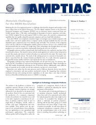
INTRODUCTION<br />
Corrosion of metallic structures is an industry and governmentwide<br />
maintenance problem that has been rapidly spreading due to<br />
the increased amount of infrastructure and military assets that are<br />
aging. However, even in the case of newer systems and components,<br />
corrosion can be a significant problem because of the harsh operational<br />
environments encountered. Recognition of the severity and<br />
the resulting economic impact of the corrosion problem by various<br />
industries and government agencies has led to significant effort over<br />
the past 50 years to prevent and control corrosion. <strong>No</strong>ndestructive<br />
evaluation (NDE) plays an important role in this effort, mostly by<br />
enabling the detection of early signs of corrosion so that corrective<br />
action can be taken before the damage becomes severe.<br />
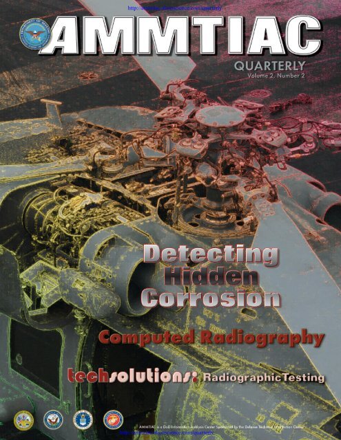
Hidden Corrosion<br />
Hidden corrosion is a type of electro-chemical material degradation<br />
that is not readily or directly detectable visually, or by<br />
any other surface measurement technique.[1] It can often be<br />
detected and quantified in terms of reduction of wall thickness or<br />
structural discontinuities such as pits, flaws and<br />
voids. When attempting to detect material<br />
degradation due to electro-chemical processes,<br />
the corrosion products (e.g., iron oxides,<br />
aluminum oxides, etc.) must be identified so<br />
that an appropriate energy source can be selected<br />
for detection.<br />
In order to perform an inspection for hidden<br />
corrosion, the detection energy source must be<br />
capable of penetrating the material in which the<br />
corrosion is hidden.[1] If the appropriate<br />
source is selected, then the returned signal will<br />
contain an evaluation of the entire material,<br />
including the physical geometry of the component<br />
or system, which may indicate its structural<br />
integrity, and any hidden corrosion. Thus,<br />
the inherent technical challenges are to select<br />
the most appropriate interrogation energy<br />
source and to recover the signal that identifies<br />
the existence of corrosion. Recovering the<br />
desired corrosion data is a mathematical inversion<br />
problem. Depending on the energy source<br />
used, the characteristics of materials, and the corrosion hidden in<br />
structural systems, an exact solution of the inversion problem may<br />
not be feasible. Therefore, data analysis and information processing,<br />
such as the use of neuro-nets, have become key enablers in<br />
developing NDE techniques for hidden corrosion.<br />
The military is considered the primary driver for the development<br />
of corrosion detection technology, while the nuclear, chemical,<br />
petroleum, and oil and gas pipeline industries are secondary<br />
drivers of this technology. This is due in part to the fact that military<br />
systems are typically fielded longer, have higher operational<br />
cycle rates and operate in more corrosive environments than commercial<br />
systems.[2] Aging DoD assets have exacerbated the problem<br />
Figure 1. An F/A-18C Hornet is Moved<br />
to the Flight Deck on an Aircraft Elevator.<br />
(Photo taken by Photographer’s<br />
Mate 3rd Class Todd Frantom and<br />
Provided Courtesy of the US Navy).<br />
of corrosion and have increased the need for prevention, hidden<br />
corrosion detection, and repair. The corrosion battle extends to<br />
essentially the entire spectrum of DoD systems, including surface<br />
ships, submarines, carrier and land-based aircraft, land vehicles, and<br />
amphibious landing craft. As systems age, corrosion becomes one of<br />
the largest cost drivers in life cycle costs of weapon systems. An<br />
example of this problem is the cables that are used for elevators on<br />
aircraft carriers (Figure 1). These cables are outside the carrier hull<br />
and are exposed to the extremely harsh corrosive environment. Due<br />
to the unavailability of NDE detection technology, these elevator<br />
cables are replaced on a time-based schedule every several years at a<br />
cost of hundreds of thousands of dollars per elevator.<br />
PRIMARY NDE METHODS FOR DETECTING<br />
HIDDEN CORROSION<br />
Guided Ultrasonic Waves<br />
Guided ultrasonic wave NDE offers the potential for a costeffective<br />
methodology for inspection of hidden corrosion in large<br />
and sometimes difficult to access areas, such as<br />
insulated piping. The field of guided waves<br />
has reached some degree of maturity, but unfortunately<br />
the number of practical applications<br />
compared to the number of research papers is<br />
rather small.<br />
Guided waves can be used in three regimes,<br />
depending on inspection distance:<br />
• Short range (
Amplitude<br />
150<br />
0<br />
-150<br />
0 50 100 150<br />
time(µs)<br />
150<br />
Figure 2. Waveforms for a Three-Layer Structure, Aluminum-<br />
Adhesive-Aluminum, (a) <strong>No</strong>n-Corroded Region, (b) Corroded Region<br />
at the Bottom, (c) Corroded Region at the Top. (Reprinted with<br />
permission from[6] © 2000 American Institute of Physics.)<br />
Guided ultrasonic waves have been applied for inspecting pipes by<br />
using an array of transducers around a pipe to focus energy at particular<br />
positions on the pipe circumference at chosen axial locations.[5]<br />
Although good results were obtained in a laboratory environment,<br />
this technique was not as successful in actual shipboard tests of piping<br />
where pipe elbows, hangers, flanges, valves, welds, etc., add significant<br />
complexity. However, this approach still has the potential to<br />
be applied to more complex structures if coherent noise can be controlled<br />
and algorithms can be developed to interpret waveforms.<br />
Prior work has shown that guided waves also have some potential<br />
for inspection of multilayer aircraft structures for hidden corrosion<br />
and cracking.[6] Figure 2 (a, b, and c) shows guided wave waveforms<br />
from a three-layer aircraft structure of aluminum-adhesivealuminum.<br />
The first signal is from a non-corroded region (Figure<br />
2a), the second is from a corroded region in the bottom aluminum<br />
plate (Figure 2b), and the third is from a corroded region in the top<br />
aluminum plate (Figure 2c).<br />
<strong>No</strong>n-contact air-coupled transducers can be used to apply guided<br />
waves to the inspection of thinning in aluminum plates.[7] In this<br />
application, a pair of micromachined gas (air)-coupled capacitive<br />
transducers is used for the generation and detection of guided plate<br />
modes. Features in the dispersive behavior of selected guided wave<br />
modes were used for the detection of plate thinning. Mode cutoff<br />
measurements provided a qualitative detection of plate thinning,<br />
while frequency shift measurements were able to provide a quantitative<br />
measure of plate thinning. The experimental setup with aircoupled<br />
transducers is shown in Figure 3.<br />
<strong>No</strong>n-contacting electromagnetic acoustic transducers (EMATs)<br />
can also be used to generate and detect shear horizontal (SH)-guide<br />
waves for inspection and mapping of corrosion in pipe walls and<br />
plates.[8] The SH waves have a pure shear-motion parallel to the<br />
surfaces and perpendicular to the plane of incidence. SH-guided<br />
waves have a unique feature in contrast to guided waves with inplane<br />
polarization; the lowest order mode has no dispersion and the<br />
dispersion of the higher order modes is much weaker than modes<br />
Receiving<br />
Module<br />
RITEC<br />
RAM-10000<br />
Gated<br />
Amplifier<br />
Amplitude<br />
(a)<br />
0<br />
-150<br />
Charge Amplifier<br />
Simulated Hidden Corrision<br />
Test Plate<br />
AC/DC<br />
Decoupler<br />
200V Bias<br />
Transmitter<br />
Receiver<br />
Control/Acquisition<br />
Computer<br />
Monitor Signals<br />
Oscilloscope<br />
Figure 3. Experimental Setup for Gas (Air) – Coupled Ultrasonic<br />
Guided Wave Detection of Thinning Defects in Aluminum Plates.[7]<br />
Amplitude<br />
(c)<br />
150<br />
0 50 100 150<br />
time(µs)<br />
0<br />
-150<br />
(b)<br />
0 50 100 150<br />
time(µs)<br />
with polarization in the plane of incidence. As a result, SH-guided<br />
waves could be economically and reliably used to detect and map<br />
corrosion in plates and pipes. Couplant free excitation and the<br />
resultant simplified waveforms add to the versatility and usefulness<br />
of the technique.<br />
A shorter range wave technique that utilizes creeping (or lateral<br />
waves) and head waves in parallel or near-parallel walled metal<br />
structures has been commercialized in the United Kingdom.[9] The<br />
technique utilizes a transducer at the critical angle to generate creeping<br />
and head waves, and a second receiving transducer is placed up<br />
to one meter away. The unique way in which the waves propagate<br />
provides complete isonification of the plate or pipe with little attenuation.<br />
This allows the probes to be well separated compared to traditional<br />
creeping wave inspection. The technique is also applicable<br />
to corrosion in pipes under pipe supports, and the instrumentation<br />
has been field proven.<br />
Ultrasonics<br />
Confidence in ultrasonic inspection to detect and quantify<br />
corrosion in field applications has often required the disassembly of<br />
systems and testing in water baths. Results of various tests have<br />
shown that the detection of hidden corrosion on various aluminum<br />
alloys of varying thickness was useful above 10% metal loss, but the<br />
technique was not applicable for metal loss below 10%.<br />
To improve the ability for detecting hidden corrosion, there have<br />
been continued efforts to apply the dripless bubbler ultrasonic scanner,<br />
which is an ultrasonic technique that does not require a water<br />
bath and disassembly.[10] This technique was selected as a primary<br />
candidate by the Air Force Logistics Center in Oklahoma City (OC-<br />
ALC) for the detection and quantification of intergranular corrosion<br />
100<br />
90<br />
80<br />
70<br />
60<br />
50<br />
40<br />
30<br />
20<br />
10<br />
0 Eddy Current A Eddy Current B Ultrasonic Testing Dripless Bubbler<br />
(Sierra Matrix)<br />
Dripless Bubbler<br />
(ISU)<br />
Thermal A<br />
Hit % – Within Shadow Hit % – Beyond Shadow False Call Rate<br />
Thermal (Wayne<br />
State Univ.)<br />
Figure 4. Corrosion Detection around Wing-Skin Fasteners –<br />
Chemically Induced Intergranular Corrosion Trial Results.[10]*<br />
prior to the onset of exfoliation around wing skin fasteners. This is a<br />
major inspection problem for aging aircraft. Figure 4 shows the<br />
results of tests for corrosion detection around wing-skin fasteners.<br />
In a similar NDE study, a novel ultrasonic pulse echo technique<br />
was developed to detect intergranular corrosion around fastener<br />
holes in aluminum wing skins before the exfoliation stage.[11] In<br />
this case, a focused transducer with a special fixture was used to<br />
overcome the typical problems: not enough couplant, transducer<br />
not perpendicular to the part, and varying transducer pressure. In<br />
general, there was good agreement between the ultrasonic results<br />
and the results from the mechanical rework of the wing skin and<br />
dissection of the fastener hole.<br />
Ultrasonics can also be applied without a water bath by using laserultrasonics.[12]<br />
Laser ultrasonics have been applied for the inspection<br />
of painted metal skin, aircraft lap joints. When lap joint corrosion<br />
reaches a specific level, normally 10% of the nominal skin thickness,<br />
the section of the lap joint must be replaced. Visual inspection of the<br />
pillowing of the surface has been used to detect this type of corrosion,<br />
but it cannot supply quantitative information. By using spectral<br />
4<br />
The <strong>AMMTIAC</strong> <strong>Quarterly</strong>, <strong>Vol</strong>ume 2, Number 2
analysis of the laser-ultrasonic waveforms,<br />
the residual metal skin thickness of the top<br />
skin of the lap joint could be determined.<br />
Results from standard samples with flatbottom<br />
holes showed that the technique<br />
could detect metal loss below 1% of the<br />
nominal thickness of the metal skin. Comparison<br />
of the laser-ultrasonic measurements<br />
to X-ray images showed that the<br />
laser-ultrasonics has the same accuracy as<br />
the X-ray imaging (metal loss below 1%).<br />
However, laser-ultrasonics as compared to<br />
X-ray imaging does not require disassembly<br />
of the structure, and the inspection could<br />
be carried out during routine maintenance.<br />
Other ultrasonic approaches for detecting<br />
hidden corrosion involve ultrasonic<br />
imaging using dry-coupled probes.[13] In<br />
addition, a commercial instrument that<br />
essentially operates as an “ultrasonic camcorder”<br />
can produce C-scan images from<br />
ultrasound signals, which are introduced<br />
into the sample with a large, unfocused<br />
commercial transducer.[14] The implementation<br />
can be either in transmission or<br />
reflection. A water squirter or ultrasonic<br />
couplant on the surface is required for the<br />
application of this technique.<br />
By combining obliquely backscattered<br />
ultrasonic signals with the sensor array<br />
real-time charge-coupled imaging system<br />
used in the ultrasonic camcorder, a rapid<br />
technique for detecting corrosion in aircraft<br />
skins without the need for paint<br />
removal has been developed.[15] The<br />
Transducer<br />
Incident Beam<br />
system can produce 30 frames a second and the unit can be programmed<br />
to examine time-of-flight bounds and thus produce 3D<br />
images of material slices. Figure 5 shows a schematic of the technique<br />
and Figure 6 shows a pulse-echo image of a corroded area in<br />
an aluminum plate. The combination of obliquely backscattered<br />
ultrasonic signals and the charged-coupled ultrasonic imager produces<br />
a viable aircraft corrosion inspection technique.<br />
Eddy Current<br />
Eddy current NDE is a prime method for detecting hidden corrosion<br />
in electrically conducting materials. The method is based on<br />
generating a localized alternating current field in the sample using a<br />
probe coil. The same probe coil or another detector then measures<br />
the material’s response to the induced eddy currents. Defects cause<br />
a perturbation in the eddy currents, and this can be detected by a<br />
change in impedance or phase variation in the detecting circuit. In<br />
the past, eddy current NDE was limited in detecting hidden corrosion<br />
to very shallow depths by the lack of penetrating capability of<br />
the eddy currents. However, over the last several years there have<br />
been several notable advances in eddy current NDE stemming from<br />
research to detect hidden corrosion and other types of defects.<br />
When combined with magnetoresistive sensors, eddy currents can<br />
be used to detect corrosion in second and third layers in aircraft lap<br />
joints.[16] High performance magnetoresistive sensors are much<br />
more sensitive than standard pick up coils used in conventional eddy<br />
current NDE, and they operate at much lower frequencies. Their<br />
low frequency range and linear response to frequency allows for<br />
much greater depth of inspection than with conventional eddy<br />
current NDE that operate at higher frequencies.<br />
Figure 5. A Schematic View of the Wavefield in a<br />
Painted 2-Layer Structure.[15]<br />
Figure 6. A Pulse-Echo Image of Corroded Area in<br />
an Aluminum Plate Visualized by the Current Sensor<br />
Array Real Time Imaging (SARTI) System. The Depth<br />
Data Represent the Information at the Crosshair<br />
Cursor Location.[15] (Reprinted with permission<br />
from SPIE)<br />
Excitational<br />
Coil<br />
Specular Reflection<br />
<strong>No</strong>n-Specular Reflection<br />
Corrosion<br />
Figure 7. Two Energy Coupling Paths in a Remote<br />
Field Eddy Current Probe for Pipe Testing.[19]<br />
Pulsed eddy current NDE technology<br />
has also made recent advances.[17] Its<br />
robustness to variations in geometry, paint<br />
thickness, rivet heads, surface warping,<br />
and sensor liftoff are allowing this technology<br />
to become a major method for detection<br />
of hidden corrosion. Conventional<br />
eddy current instruments measure the<br />
impedance and reactance of the detection<br />
coil, while the pulsed eddy current instrument<br />
measures the transient voltage signal<br />
with a frequency spectral content from<br />
direct current to 100 KHz or higher. This<br />
broadband characteristic provides the ability<br />
to conduct digital signal analysis and to<br />
extract subtle differences in waveforms<br />
associated with small geometry variations.<br />
Hence, it provides the ability to quantify a<br />
large number of parameters. For example,<br />
material loss at or near the surface will<br />
have more of an effect on the early-time<br />
portion of the total transient interval than<br />
on the late-time portion. The opposite<br />
will be true for very deep defects.<br />
Remote field eddy current is another<br />
variation of conventional eddy current<br />
that has found widespread use in detecting<br />
hidden corrosion. Its capabilities have<br />
recently been expanded and automated.[18]<br />
The remote field eddy current<br />
technique is based on the measurement of<br />
the voltage induced in a pickup coil by<br />
flux which has passed twice through the<br />
test piece as shown in Figure 7. Measurement<br />
of the phase change caused by a discontinuity<br />
has a linear relationship with changes in thickness of the<br />
pipe wall. Remote field eddy current is not sensitive to liftoff, but an<br />
ultra sensitive eddy current system is required to handle the very low<br />
amplitude signals obtained from remote field eddy current probes.<br />
Magneto-optical imaging of eddy currents is another innovative<br />
advance in eddy currents applied to detection of hidden corrosion.[20]<br />
Magneto-optical imaging of the eddy currents generates<br />
real-time images of large surface areas to quickly detect subsurface<br />
corrosion and cracking. Although eddy current techniques do not<br />
have as much sensitivity and spatial resolution as ultrasonic NDE<br />
techniques, the ability to detect corrosion in multiple layer structures<br />
and at greater depths are advantageous.<br />
Thermography<br />
Thermography provides a fast, non-contact technique for detection<br />
of subsurface corrosion. Thermography is based on using the thermal<br />
differences between a material and material defects to image<br />
discontinuities such as corrosion. It has demonstrated ability to<br />
detect corrosion under paint without paint removal. In addition,<br />
advances in commercial instrumentation and algorithms, particularly<br />
for thermal wave techniques[21], have substantially enhanced<br />
field applications. Moving linear heat sources have also enhanced<br />
thermographic capability.<br />
Thermal wave systems operate by sending a pulse of heat from the<br />
surface into the material, where it undergoes thermal reflection at<br />
either the rear surface or at thermal impedance changes (e.g. corrosion).<br />
The effect of these thermal reflections is that it modifies the<br />
local cooling rate at the surface. The cooling rate, in turn, is monitored<br />
through its effect on the IR radiation from the surface. The IR<br />
http://ammtiac.alionscience.com The <strong>AMMTIAC</strong> <strong>Quarterly</strong>, <strong>Vol</strong>ume 2, Number 2 5<br />
Paint<br />
Skin<br />
Primer<br />
Bond<br />
Substructure (Stiffener, T-Cap, Stringer, etc.)<br />
Indirect Energy Coupling Path<br />
Direct Energy Coupling Path<br />
Indirect Energy Coupling Path<br />
Pick-up<br />
Coil
6<br />
radiation is detected by an IR camera and processed as a sequence of<br />
images by the control computer.<br />
Figure 8 shows a thermal wave image of two KC-135 wing fastener<br />
regions, one with corrosion and one without. The authors concluded<br />
that thermal wave imaging is an excellent tool for inspecting<br />
aircraft for corrosion and can rapidly (in the matter of a few seconds)<br />
make quantitative measurement of less than 1.0% material<br />
loss. Thermal waves can also be used to detect corrosion under paint<br />
on airplane skin in the presence of irregular paint thickness. This<br />
work was validated in a blind test on a DC-9 belly skin.[22]<br />
A number of other heat source techniques applied to thermography<br />
to detect corrosion have been demonstrated. Hot air guns as<br />
heat sources for thermography (named fan thermography) have<br />
been shown to detect corrosion in aircraft structures.[23] A quartz<br />
line-shaped heat source (3000 watt quartz lamp with an elliptical<br />
reflector) moving at speeds of 2.5 to 12.2 cm/sec has also been<br />
demonstrated to provide a back surface profile.[24] Using neural<br />
nets for mapping the data, metal thickness could be determined to<br />
within 5% of the actual thickness.<br />
Thermographic NDE techniques are not currently in widespread<br />
use. However, the rapid inspection times for broad areas of coverage,<br />
availability of instrumentation, and ease of use should quickly<br />
lead to a wider use in the field.<br />
CONCLUSIONS<br />
In the past, NDE of hidden corrosion was a difficult challenge.<br />
However, in the last decade substantial advances in NDE methodology<br />
and software have made the challenge much more tractable.<br />
For example, eddy current can now detect corrosion in second and<br />
third layers of aircraft lap joints. Pulsed eddy current NDE, low frequency<br />
eddy current NDE with magnetoresisitive sensors, remote<br />
field eddy current NDE at low frequencies using Hall probes, and<br />
magneto-optical imaging of eddy currents have greatly increased the<br />
tools available to detect hidden corrosion.<br />
Thermography has also undergone great advances in the past<br />
decade, and it is now widely used to detect corrosion under paint.<br />
Advances in commercial instrumentation and software, particularly<br />
for thermal wave imaging, have enhanced field applications. Moving<br />
linear heat sources and algorithms have also broadened the field<br />
applications of conventional thermography. These advances in thermography,<br />
coupled with wide field of view and rapid inspection<br />
times, will result in the continued expansion of field applications.<br />
In the past, ultrasonic techniques were mainly limited to inspecting<br />
disassembled systems in a water bath. However, advances in ultrasonic<br />
methods (e.g. the dripless bubbler) have now expanded the applications<br />
for detecting corrosion. In addition, laser ultrasonics should continue<br />
to find niche field applications as it has over the past decade, but<br />
the rate of market penetration will most likely remain very modest due<br />
to the complexity of the technique. Guided wave ultrasonics has been<br />
shown in a number of research settings to be capable of inspecting large<br />
areas for hidden corrosion in difficult to access areas. However, transition<br />
of this capability, with its complex analysis, to commercial applications<br />
is expected to continue to proceed very slowly.<br />
Other NDE techniques, such as X-ray radiology and optical techniques,<br />
should continue to find niche field applications. In summary,<br />
the future looks bright for existing techniques and for improving<br />
field NDE capability to detect hidden corrosion.<br />
The <strong>AMMTIAC</strong> <strong>Quarterly</strong>, <strong>Vol</strong>ume 2, Number 2<br />
Figure 8. Thermal Wave Image<br />
of Two KC-135 Wing Fastener<br />
Regions, One Revealing Subsurface<br />
Intergranular Corrosion,<br />
Extending from the Lower Right<br />
Edge of the Fastener (Left);<br />
the Other with <strong>No</strong> Corrosion<br />
(Right).[21] (Reprinted with<br />
permission from SPIE.)<br />
NOTE AND REFERENCES<br />
* Shadow refers to the shadow of the fastener countersink.<br />
[1] J.C.I. Chang, “Aging Aircraft Science and Technology Issues and Challenges<br />
and USAF Aging Aircraft Program”, Structural Integrity in Aging Aircraft, ASME:<br />
AD-<strong>Vol</strong>. 47, 1995.<br />
[2] “Corrosion Detection Technologies”, BDM Federal Inc., March 1998.<br />
[3] R.P. Dalton, P. Cawley and M.J.S. Lowe, “Propagation of Acoustic Emission<br />
Signals in Metallic Fuselage Structure,” IEEE Proceedings: Science, Measurement and<br />
Technology, <strong>Vol</strong>. 148, 2001a, pp. 169-177.<br />
[4] R.P. Dalton, P. Cawley and M.J.S. Lowe, “The Potential of Guided Waves for<br />
Monitoring Large Areas of Metallic Aircraft Fuselage Structure,” Journal of NDE,<br />
<strong>Vol</strong>. 20, 2001b, pp. 29-46.<br />
[5] M.J. Quarry and J.L. Rose; “Multimode Guided Wave Inspection of Piping<br />
Using Comb Transducers,” <strong>Materials</strong> Evaluation, <strong>Vol</strong>. 57, <strong>No</strong>. 10, October 1999, pp.<br />
1089-1090.<br />
[6] L.E. Soley and J.L. Rose, “Ultrasonic Guided Waves for the Detection of Defects<br />
and Corrosion in Multi-Layer Structures,” Review of Progress in Quantitative<br />
<strong>No</strong>ndestructive Evaluation, <strong>Vol</strong>. 19B, 2000, pp. 1801-1808.<br />
[7] D. Tuzzeo and F. Lanza di Scalea, “<strong>No</strong>ncontact Air-Coupled Guided Wave<br />
Ultrasonics for Detection of Thinning Defects in Aluminum Plates,” Research in<br />
<strong>No</strong>ndestructive Evaluation, <strong>Vol</strong>. 13, <strong>No</strong>. 2, 2001, pp. 61-77.<br />
[8] H.J. Salzburger, “Long Range Detection of Corrosion by Guided Shear Horizontal<br />
(SH-) Waves,” The 7th European Conference on <strong>No</strong>n-Destructive Testing, Copenhagen,<br />
May 1998, pp. 751-757.<br />
[9] F. Ravenscroft and C. Bull, “Corrosion Detection Using CHIME,” Insight,<br />
<strong>Vol</strong>. 42, <strong>No</strong>. 2, February 2000, pp. 80-83.<br />
[10] D.J. Barnard and D.K. Hsu, “Detection and Quantification of Intergranular Corrosion<br />
Around Wing Skin Fasteners Using the Dripless Bubbler Ultrasonic Scanner,” Review<br />
of Progress in Quantitative <strong>No</strong>ndestructive Evaluation, <strong>Vol</strong>. 18B, 1999, pp. 1821-1828.<br />
[11] P.S. Rutherford, “NDI Method to Locate Intergranular Corrosion Around<br />
Fastener Holes in Aluminum Wing Skins,” SPIE, <strong>Vol</strong>. 3397, 1998, pp. 57-66.<br />
[12] M. Choquet, D. Levesque, M. Massabki, C. Neron, N.C. Bellinger, D. Forsyth,<br />
C.E. Chapman, R. Gould, J.P. Komorowski and J.P. Monchain, “Laser-Ultrasonic<br />
Detection of Hidden Corrosion in Aircraft Lap Joints: Results from Corroded<br />
Samples,” Review of Progress in Quantitative <strong>No</strong>ndestructive Evaluation, <strong>Vol</strong>. 20B,<br />
2001, pp. 300-307.<br />
[13] I.N. Komsky, “Ultrasonic Imaging of Hidden Defects Using Dry-coupled<br />
Ultrasonic Probes,” Health Monitoring and Smart <strong>No</strong>ndestructive Evaluation of<br />
Structural and Biological Systems V, edited by Tribikram Kundu, Proc. of SPIE,<br />
<strong>Vol</strong>. 61770M, 2006.<br />
[14] M. Lasser, B. Lasser, J. Kula and G. Rohrer, “Developments in Real-Time 2D<br />
Ultrasound Inspection for Aging Aircraft,” SPIE Conference on <strong>No</strong>ndestructive Evaluation<br />
of Aging Aircraft, Airports, and Aerospace Hardware III, <strong>Vol</strong>. 3586, 1999, pp. 78-84.<br />
[15] Y. Bar-Cohen, A.K. Mal and M. Lasser, “NDE of Hidden Flaws in Aging<br />
Aircraft Structures Using Obliquely Backscattered Ultrasonic Signals (OBUS),” The<br />
SPIE Conference on <strong>No</strong>ndestructive Evaluation of Aging Aircraft, Airports, and Aerospace<br />
Hardware III, <strong>Vol</strong>. 3586, 1999, pp. 347-353.<br />
[16] R. Rempt, “Scanning with Magnetoresistive Sensors for Subsurface Corrosion,”<br />
Review of Quantitative <strong>No</strong>ndestructive Evaluation, <strong>Vol</strong>. 21B, 2002, pp. 1771-1778.<br />
[17] S. Giguere, B.A. Lepine and J.M.S. Dubois, “Pulsed Eddy Current Technology:<br />
Characterizing Material Loss with Gap and Lift-off Variations,” Research in<br />
<strong>No</strong>ndestructive Evaluation, <strong>Vol</strong>. 13, <strong>No</strong>.3, 2001, pp. 119-129.<br />
[18] M.S. Safizadeh, Z. Liu, C. Mandache, D.S. Forsyth and A. Fahr, “Automated<br />
Pulsed Eddy Current Method for Detection and Classification of Hidden<br />
Corrosion,” Proc. Vth International Workshop, Advances in Signal Processing for<br />
<strong>No</strong>n Destructive Evaluation of <strong>Materials</strong>, Quebec City (Canada), 2-4 Aug. 2005,<br />
X. Maldague ed., E. du Cao, 2006, pp. 75-84.<br />
[19] Y.S. Sun, T. Ouang and S. Upda, “Remote Field Eddy Current Testing: One<br />
of the Potential Solutions for Detecting Deeply Embedded Discontinuities in Thick<br />
and Multilayer Metallic Structures,” <strong>Materials</strong> Evaluation, <strong>Vol</strong>. 59, <strong>No</strong>. 5, May 2001,<br />
pp. 632-637.<br />
[20] D.K. Thome, “Development of an Improved Magneto-Optic/Eddy-Current<br />
Imager,” Published by The National Technical Information Service (NTIS), Springfield,<br />
Virginia, April 1998.<br />
[21] L.D. Favro, R.L. Thomasand and X. Han, “State-of-the-Art of Thermal Wave<br />
Imaging for NDE of Aging Aircraft,” <strong>No</strong>ndestructive Evaluation of Aging Aircraft,<br />
Airports, and Aerospace Hardware III, SPIE <strong>Vol</strong>. 3586, March 1999, pp. 94-97.<br />
[22] X. Han, L.D. Favro, L. Li, Z, Ouyang, G. Sun, R.L. Thomas and D.M.<br />
Ahsbaugh, “Quantitative Thermal Wave Corrosion Measurements on a DC-9 Belly<br />
Skin in the Presence of Irregular Paint Thickness Variations,” Review of Progress in<br />
Quantitative <strong>No</strong>ndestructive Evaluation, <strong>Vol</strong>. 20A, 2001, pp. 483-486.<br />
[23] N. Meyendorf, J. Hoffman and E. Shell, “Early Detection of Corrosion in<br />
Aircraft Structures,” Review of Quantitative <strong>No</strong>ndestructive Evaluation, <strong>Vol</strong>. 21B,<br />
2002, pp. 1792-1797.<br />
[24] W.P. Winfree and K.E. Cramer, “Reconstruction of Back Surface Profiles from<br />
Scanned Thermal Line Source Data Using Neural Networks,” Review of Progress in<br />
Quantitative <strong>No</strong>ndestructive Evaluation, <strong>Vol</strong>. 19A, 2000, pp. 691-698.
techsolutions 5<br />
Brett J. Ingold<br />
<strong>AMMTIAC</strong><br />
Rome, NY<br />
A Selecting Brief Introduction a <strong>No</strong>ndestructive to Precious Testing Metals Method, Part IV: Radiography<br />
This edition of TechSolutions is the fourth installment in a series dedicated to the subject of nondestructive testing.<br />
TechSolutions 1, published in <strong>Vol</strong>. 1, <strong>No</strong>. 2 of the <strong>AMMTIAC</strong> <strong>Quarterly</strong>, introduced the concept of nondestructive<br />
testing and provided brief descriptions of the various techniques currently available. TechSolutions 2 and 3, published<br />
in subsequent issues of the <strong>AMMTIAC</strong> <strong>Quarterly</strong>, focused on visual inspection and eddy current testing. The current<br />
article continues the series and provides a general and informative overview of the radiography nondestructive testing<br />
method. In addition, this article will highlight some of the physical principles, inspection requirements, and implementation<br />
considerations involved in an effective radiographic inspection process. 1 Once the series on nondestructive testing<br />
methods is complete, we will combine all of the articles into a valuable desk reference on nondestructive testing and place<br />
it on our website. – Editor<br />
INTRODUCTION<br />
After visual and optical testing (VT), the next method of nondestructive<br />
testing (NDT) most commonly employed in industry is<br />
radiographic testing. Also simply referred to as radiography, it is<br />
perhaps the most versatile of the nondestructive testing methods.[1]<br />
The basic radiographic process in use today is in large part<br />
still the same as it was when it was introduced in the late 1800s.<br />
Radiography uses radiation energy to penetrate solid objects in<br />
order to assess variations in thickness or density. The second part<br />
of the process involves capturing a shadow image of the component<br />
being inspected on film using procedures similar to those that<br />
technicians used when the technology was first<br />
developed. Identifying density differences on an<br />
X-ray, which indicate flaws or cracks, is still the<br />
foundation of radiographic analysis.<br />
Beam<br />
PHYSICAL PRINCIPLES<br />
Radiography basically involves the projection<br />
and penetration of radiation energy through the<br />
sample being inspected. The radiation energy is<br />
absorbed uniformly by the material or component<br />
being inspected except where variations in<br />
thickness or density occur. The energy not<br />
absorbed is passed through to a sensing medium<br />
that captures an image of the radiation pattern.<br />
The uniform absorption and any deviations in<br />
uniformity are subsequently captured on the<br />
sensing material and indicate the potential presence<br />
of a discontinuity.<br />
Image Capturing Media<br />
In simple terms, a radiograph is a photographic record produced by<br />
the passage of X-rays or gamma rays through an object onto a film<br />
or other recording medium (see Figure 1). The developing, fixing<br />
and washing of the film after exposure can be performed manually<br />
or by automated processing equipment. The development<br />
process begins after the film is exposed to the radiation and an<br />
invisible change called a latent image develops on the film emulsion.<br />
These exposed areas become dark when the film is placed in<br />
Flaw<br />
Radiation Source<br />
Test Piece<br />
(Object)<br />
Medium for<br />
Converting<br />
the Radiation<br />
Image of Flaw<br />
Figure 1. Diagram of Typical<br />
Radiography Test Setup.[2]<br />
a developing solution. The degree of darkening that occurs during<br />
this process depends on the amount of exposure that occurred. The<br />
next step is to place the film into a special bath and rinse it to stop<br />
the development process. Lastly, the film is put into a fixing bath<br />
and then washed to remove the fixer solution. At this point the<br />
film is fully developed, the process is complete and the radiograph<br />
is ready to be handled and analyzed.[1]<br />
As the digital world has evolved, a quicker and much more<br />
efficient alternative to the meticulous film development process<br />
has also emerged to benefit the radiography NDT community.<br />
Computed radiography, which is described in<br />
the related article entitled “Computed Radiography<br />
in the Pacific <strong>No</strong>rthwest: Benefits, Drawbacks<br />
and Requirements”, makes use of an<br />
alternative image capturing media and development<br />
process.<br />
Electromagnetic Radiation<br />
Two types of electromagnetic radiation are used<br />
to perform radiographic inspection: X-rays and<br />
gamma rays (see Figure 2). The primary distinguishing<br />
characteristic between these two types<br />
of radiation is the different wavelengths of the<br />
electromagnetic energy. Compared to other<br />
types of radiation both X-rays and gamma rays<br />
have relatively short wavelengths which allows<br />
them to penetrate opaque materials. This<br />
inherent capability is what enables their use<br />
for nondestructive testing, as they can reveal<br />
flaws embedded in visually non-transparent materials. The advent<br />
of radiography came quickly after the discovery of X-rays because<br />
of the penetration properties of this electromagnetic energy.[3]<br />
Types of Discontinuities<br />
A number of different types of discontinuities can be detected<br />
with radiographic NDT. Table 1 lists the suitability of traditional<br />
radiographic NDT methods for identifying various types of<br />
discontinuities in several applications.<br />
http://ammtiac.alionscience.com The <strong>AMMTIAC</strong> <strong>Quarterly</strong>, <strong>Vol</strong>ume 2, Number 2<br />
7
techsolutions 5<br />
X-Rays<br />
Visible<br />
10 -2 10 2 10 4 10 6<br />
Gamma Rays Ultraviolet Infrared<br />
Wavelengths in angstrom units (A), where 1 A = 10 -8 cm = 3.937x10 -9 in.<br />
Figure 2. Electromagnetic<br />
Spectrum Showing X-ray and<br />
Gamma Ray Regions.[1]<br />
10 0 A review of radiographs from an F-15 Eagle to<br />
INSPECTION REQUIREMENTS<br />
Several critical elements are required to successfully analyze the<br />
results of radiographic testing. Because of differences in density<br />
and variations in composition, different test pieces can absorb<br />
varying amounts of radiation and therefore present a range of<br />
results. Technicians and radiologists each require several years of<br />
training to properly set up and administer tests and inspections<br />
and to learn how to evaluate<br />
and interpret the results.<br />
Also, as the industry continues<br />
to develop, some forecasts<br />
suggest that in the<br />
future X-rays will be read<br />
almost exclusively by computers.<br />
This specific advancement,<br />
however, would not<br />
A non-destructive inspection technician<br />
(NDI) evaluates an X-ray image of<br />
an A-10 Thunderbolt II aircraft nose<br />
landing gear door for cracks. NDI<br />
technicians are tasked with finding<br />
and confirming discontinuities on the<br />
airframe and its parts using methods<br />
such as Eddy Current, Fluorescent<br />
Penetrant, Magnetic Particles, Ultra<br />
Sound and X-ray. (Photo taken by<br />
Airman 1st Class Alesia Goosic and<br />
provided courtesy of US Air Force)<br />
necessarily eliminate the<br />
high costs associated with<br />
set up tasks, which consumes<br />
a significant portion<br />
of the total radiographic<br />
inspection time.<br />
Safety<br />
Safety is an important issue<br />
to consider when evaluating<br />
a new process for implementation,<br />
especially one such as radiography that requires the<br />
use of radiation. Several governing bodies, including local and<br />
state governments, work together to closely monitor anyone who<br />
works with radiography equipment to ensure that the highest<br />
levels of safety are consistently met.<br />
The licensing and certification process for individuals working<br />
with radiography equipment, which emits radiation, requires<br />
both a written examination and an assessment of specific skills<br />
while using the equipment. The primary governing body that<br />
administers the written examination is the American Society of<br />
<strong>No</strong>ndestructive Testing (ASNT). The practical skills evaluation<br />
can be conducted by a variety of institutions that have approval<br />
from ASNT. With successful completion of these safety requirements,<br />
the applicant will be certified as an Industrial Radiography<br />
Radiation Safety Personnel (IRRSP) member. ASNT<br />
offers more detailed information on the entire certification<br />
process, including a more specific list of requirements.[4]<br />
PRACTICAL CONSIDERATIONS<br />
There are several factors to take into account when considering<br />
the implementation of a radiographic inspection program. Some<br />
of the most important factors include: cost, density, facility size<br />
and logistics. Compared to other nondestructive testing methods,<br />
radiography is expensive. Relatively large costs can be<br />
reduced considerably when portable X-ray or gamma-ray sources<br />
are used in film radiography because this setup only requires<br />
space for film processing and analysis. With real-time radiography,<br />
operating costs are usually much lower, because setup times<br />
are shorter and there are no extra costs for processing or interpretation<br />
of film.<br />
Advantages and Disadvantages<br />
Like all other NDT methods, there are several advantages<br />
and disadvantages that factor into deciding where and when<br />
radiography is typically applied. In relation to other commonly<br />
used NDT methods, the well-proven method of radiography<br />
has three main advantages: the ability to detect internal<br />
flaws, the ability to detect significant variations in composition,<br />
and the ability<br />
to establish a<br />
permanent record<br />
of raw inspection<br />
data. Radiography<br />
also presents<br />
test results pictorially<br />
which can be<br />
much more readily<br />
interpreted than<br />
numerical data.<br />
In addition, realtime<br />
radiography<br />
check for foreign object debris and cracks<br />
in the aircraft's structure. (Photo taken by<br />
Staff Sgt. Shelley Gill and provided courtesy<br />
offers the ability of US Air Force)<br />
to rotate a test<br />
object during inspection, which improves detection of both<br />
internal and external flaws due to the ability to find the optimum<br />
orientation.<br />
On the negative side, orientation of the sample to be<br />
inspected is a key to successful radiographic inspection and<br />
therefore can pose difficulties if the proper orientation is not<br />
found. For example, radiography is not as effective at detecting<br />
flaws that are oriented in a planar direction with respect to the<br />
radiation source. Thick inspection samples are also problemat-<br />
8<br />
The <strong>AMMTIAC</strong> <strong>Quarterly</strong>, <strong>Vol</strong>ume 2, Number 2
<strong>AMMTIAC</strong><br />
A DVANCED M ATERIALS, MANUFACTURING AND T ESTING<br />
Table 1. Suitability of Traditional Radiographic NDT Methods for Various Types of Discontinuities in Light and Heavy Metals.[3]<br />
Suitability for Light Metals<br />
Suitability for Heavy Metals<br />
Inspection Application Film Real-Time Film Film Real-Time Film<br />
General<br />
with X-rays Radiography with γ-rays with X-rays Radiography with γ-rays<br />
Surface cracks* 3 3 3 3 3 3<br />
Internal cracks 3 3 3 3 3 3<br />
Voids 4 4 4 4 4 4<br />
Thickness 3 4 3 3 4 3<br />
Metallurgical variations 3 3 3 3 3 3<br />
Sheet and plate<br />
Thickness 4 4 4 4 4 4<br />
Laminations 1 1 1 1 1 1<br />
Voids 4 4 4 4 4 4<br />
Bars and tubes<br />
Seams 2 2 2 2 2 2<br />
Pipe 4 4 4 4 4 3<br />
Cupping 4 4 4 4 4 3<br />
Inclusions 3 3 3 3 3 3<br />
Castings<br />
Cold shuts 4 4 4 4 4 4<br />
Surface cracks 3 3 3 3 3 3<br />
Internal shrinkage 4 4 4 4 4 4<br />
Voids, pores 4 4 4 4 4 4<br />
Core shift 4 4 4 4 4 4<br />
Forgings<br />
Laps 2 2 2 2 2 1<br />
Inclusions 3 3 3 3 3 1<br />
Internal bursts 4 4 4 3 3 4<br />
Internal flakes 2 2 1 2 2 1<br />
Cracks and tears 3 3 3 3 3 3<br />
Welds<br />
Shrinkage cracks 4 4 4 4 4 4<br />
Slag inclusions 4 4 4 4 4 4<br />
Incomplete fusion 4 4 4 4 4 4<br />
Pores 4 4 4 4 4 4<br />
Incomplete penetration 4 4 4 4 4 4<br />
Processing<br />
Heat-treat cracks 1 1 1 2 1 1<br />
Grinding cracks 1 1 1 1 1 1<br />
Service<br />
Fatigue and heat cracks 3 3 2 2 2 2<br />
Stress corrosion 3 3 2 3 3 2<br />
Blistering 2 2 2 2 2 2<br />
Thinning 3 3 3 3 3 3<br />
Corrosion pits 3 3 2 4 4 2<br />
4 - Good, 3 - Average, 2 - Fair, 1 - Poor<br />
ic for radiography methods. Radiation sources can pose health<br />
and safety risks which is another disadvantage of the method.<br />
The tedious film processing requirement of radiography and<br />
associated special facility requirements have traditionally been<br />
a distinct disadvantage; however, with the advent of digital<br />
imaging and computed radiography many of these limitations<br />
have been overcome.<br />
CURRENT TRENDS AND FUTURE ADVANCEMENTS<br />
In order to meet the constantly changing demands of industry,<br />
various new sources of radiation, such as neutron generators<br />
and radioactive isotopes, are continually being developed.<br />
Other ongoing advances also include improved X-ray films and<br />
automatic film processors, as well as improved or specialized<br />
radiographic techniques.<br />
http://ammtiac.alionscience.com The <strong>AMMTIAC</strong> <strong>Quarterly</strong>, <strong>Vol</strong>ume 2, Number 2 9
techsolutions 5<br />
However, with today’s technology it is now possible to generate<br />
images of higher quality and sensitivity. The higher quality of<br />
radiographic images is primarily due to improved films that have<br />
a wider variety of available grain sizes. Also, with the addition of<br />
computers and other advanced electronic systems to the process,<br />
the advent of digital radiography has proved to be a large<br />
advancement within the industry.<br />
With the use of digital radiography, a radiographic image captured<br />
today can theoretically be preserved forever and sent anywhere<br />
in the world almost instantly. In earlier cases, there had to<br />
be concerns with deterioration of the image that no longer have<br />
to be taken into account today. This ability to continually<br />
improve the process has led to growth of radiography into<br />
numerous industries. Radiography has seen expanded use in<br />
industry to inspect welds and castings, airbags and canned foods,<br />
to name a few. The area of metallurgical material identification<br />
and security systems has also employed radiography NDT at airports<br />
and other facilities with security needs.[1, 5]<br />
CONCLUSION<br />
Radiography is a mature NDT method that can be used to effectively<br />
detect several types of discontinuities embedded within a<br />
variety of types of materials and components. Since the method<br />
has been in use for many years, the drawbacks and shortcomings<br />
are well-known. Some of these limitations have been overcome<br />
with the rapid advancement of digital technology. Radiography<br />
has continued to evolve by embracing certain aspects of the<br />
digital era, and consequently it has become a more flexible and<br />
viable method for nondestructive evaluation.<br />
REFERENCES<br />
[1] “Radiography in Modern Industry,” 4th Edition, R.A. Quinn<br />
and C.C. Sigl, Editors, Eastman Kodak Company, 1980, http://<br />
www.kodak.com/eknec/documents/87/0900688a802b3c87/Radiogra<br />
phy-in-Modern-Industry.pdf<br />
[2] “Radiography Testing,” Engineer’s Handbook, http://www.engi<br />
neershandbook.com/MfgMethods/ndtrt.htm<br />
[3] “Radiographic Inspection,” ASM Metals Handbook, Ninth<br />
Edition, <strong>Vol</strong>. 17, <strong>No</strong>ndestructive Evaluation and Quality Control,<br />
ASM International Metals Park, OH, pp. 296-357.<br />
[4] “Industrial Radiography Radiation Safety Personnel,” ASNT<br />
Practice <strong>No</strong>. ASNT-CP-IRRSP-1A, 2001 Edition, American Society<br />
for <strong>No</strong>ndestructive Testing, http://www.asnt.org/certification/irrsp/<br />
cp-irrsp-1a.pdf.<br />
[5] “Introduction to Radiographic Testing,” NDT Resource Center,<br />
http://www.ndted.org/EducationResources/CommunityCollege/Radio<br />
graphy/Introduction/presentstate.htm.<br />
Table 1. Radiography Summary<br />
Discontinuity types<br />
(e.g. what types the method can detect)<br />
Size of discontinuities<br />
Limitations<br />
Advantages<br />
Inspector training (level and/or availability)<br />
Inspector certification required<br />
Equipment<br />
Relative cost of inspection<br />
• Voids<br />
• Inclusions<br />
• Cracks<br />
• <strong>No</strong>n-uniformity of material<br />
• Density changes<br />
• Weld defects<br />
• Discontinuities that exhibit 1% or more absorption difference relative to surrounding region<br />
• <strong>Advanced</strong> systems can detect flaws as small as 0.001 inches<br />
• Orientation of inspection sample<br />
• <strong>No</strong>t suitable for surface defects<br />
• As thickness increases, detection effectiveness decreases<br />
• Large amounts of equipment required for non-portable setup<br />
• Film limitations<br />
• Manual image interpretation<br />
• Can be used to detect defects in a variety of materials<br />
• Can detect internal defects<br />
• Permanent inspection record<br />
• Objects radiographed range in size from micro-miniature electronic parts to<br />
large missile components<br />
• Makes it easier to maintain a defect-free and uniform product line<br />
• Variety of programs available nationally to study the science of radiology<br />
• Radiation safety training is critically important<br />
• ASNT offers certification for radiography safety<br />
• Portable or fixed setups depending on industry/company requirements and desired function<br />
• Traditional radiography requires film development facilities and equipment<br />
• Depends on setup, but cost can be greatly reduced with the use of portable equipment<br />
that requires less space<br />
10<br />
The <strong>AMMTIAC</strong> <strong>Quarterly</strong>, <strong>Vol</strong>ume 2, Number 2
Greg A. Levcun<br />
Naval Facilities Engineering Command <strong>No</strong>rthwest<br />
Christopher S. Mahendra<br />
Naval Air Systems Command<br />
INTRODUCTION<br />
Like many other Navy regions, Commander Navy Region<br />
<strong>No</strong>rthwest (CNRNW) was faced with replacing its aging<br />
chemical and film-based radiographic imaging systems that<br />
were being used for nondestructive testing (NDT). At<br />
CNRNW, several activities acquired computed radiography<br />
(CR) systems via the Pollution Prevention Equipment Program<br />
(PPEP) to replace the conventional NDT systems. The new<br />
CR systems have been installed and used, and the intent of this<br />
article is to report on the benefits, requirements,<br />
concerns, and problems associated<br />
with implementing this new technology for<br />
CNRNW.<br />
Why the Move Away from Film<br />
Several factors are influencing the move away from film-based<br />
X-ray techniques toward CR systems. CR systems eliminate<br />
costly chemicals and resulting hazardous waste, provide an<br />
adaptable image medium, reduce other consumables that filmbased<br />
systems require, protect worker health and safety,<br />
improve productivity by reducing work turn-around time and<br />
make test results readily available to off-site experts. Each of<br />
these benefits is described in the following sections.<br />
THE BASICS OF COMPUTED<br />
RADIOGRAPHY SYSTEMS<br />
Computed radiography is a type of digital<br />
radiography. Similar to conventional radiography,<br />
CR systems create an X-ray image of<br />
the part under inspection. Unlike a filmbased<br />
system, however, the end result is a digital<br />
image. (The sidebar contains a summary<br />
of three radiography inspection technologies).<br />
CR systems have four main elements,<br />
including a phosphor image plate (IP), an IP<br />
reader (see Figure 1), a central processing station<br />
with special software (see Figure 2), and<br />
a high-resolution monochrome X-ray monitor.<br />
The IP surface is coated with storage<br />
phosphors that capture and store the incident<br />
radiation energy from the X-ray source to create a latent image<br />
on the plate. After the IP is exposed to the radiation energy it is<br />
processed in the IP reader where a low energy laser is used to<br />
release visible light from the stored energy. The visible light is<br />
then converted into an electrical signal which can be converted<br />
into digital data. The storage image phosphors will retain the<br />
latent image for periods ranging from several hours to days,<br />
depending on screen phosphor material and exposure duration;<br />
however, the plates can be reused numerous times once the latent<br />
image is cleared. Similar to conventional X-ray film, phosphor<br />
plates are stored in cassette format.<br />
Figure 1. An NDI Inspector Works with the<br />
IP and Reader.<br />
Figure 2. An Inspector Looks at Two Views<br />
of a Defect.<br />
Elimination of Chemicals and Hazardous <strong>Materials</strong><br />
With CR systems, images are generated on a medium that<br />
does not require the chemical bath processing used for<br />
producing traditional film. Moreover, traditional film<br />
chemicals must be used within a limited timeframe, which<br />
requires processing labs to maintain a fresh stock of chemicals.<br />
The cost of procuring and maintaining these supplies<br />
is expensive, and the film developing chemicals must be<br />
disposed of as hazardous waste. Therefore, by utilizing<br />
the CR systems, chemicals and hazardous materials are<br />
eliminated.<br />
http://ammtiac.alionscience.com The <strong>AMMTIAC</strong> <strong>Quarterly</strong>, <strong>Vol</strong>ume 2, Number 2<br />
11
Adaptable Image Medium<br />
Computed radiography’s IP is typically only 0.025 inch thick<br />
and can easily be cut with scissors or a knife. Image plates can<br />
be shaped to meet specific imaging needs, although the cut portion<br />
must be refit onto a standard size IP for reading the image.<br />
Reduction of Consumables and Lab Equipment<br />
The imaging plates can be reused between 200 and 5,000<br />
times, unlike traditional X-ray film, which can only be used<br />
once. Other consumables eliminated by using CR include<br />
envelopes, marking pencils, cleaning materials, gloves, and<br />
shields. Computed radiography systems also eliminate several<br />
pieces of support equipment in addition to the developing<br />
tanks and processors, including water chillers, safe lights, silver<br />
recovery units, light-tight doors or light traps, film viewers,<br />
and densitometers used for checking film density and proper<br />
exposure settings.<br />
Worker Health and Safety<br />
Compared to conventional radiography techniques, CR test<br />
operators are not exposed to film processing chemicals and are<br />
subjected to significantly less radiation. The ALARA concept<br />
(“As Low As Reasonably Achievable”) is used within the Navy<br />
to control radiation exposure. In order to comply with<br />
ALARA, an operator must use some combination of time,<br />
distance, and shielding to minimize exposure. In the case of<br />
CR, both the amount of radiation and the length of exposure<br />
are significantly reduced compared to film, which makes the<br />
operator’s task safer and faster.<br />
Productivity Improvements<br />
The opportunities for productivity improvements are substantial<br />
as a result of using CR. First, the reduced radiation dose per<br />
exposure and shorter exposure times per shot allow CR inspections<br />
to occur within a smaller shielded area. This contributes<br />
to quicker inspection site set-up and allows other work efforts<br />
to continue nearby. The decreased exposure times also make the<br />
inspection process shorter, reducing personnel time. Second,<br />
image processing times are down from a minimum of 12 minutes<br />
for film to one minute for CR. This enables the system<br />
operator to determine quickly if shots are acceptable or need to<br />
be retaken. Third, with CR an operator can manipulate the<br />
presentation density and inspect a wider range of material<br />
thicknesses with a single exposure on a single imaging plate as<br />
opposed to taking multiple film shots that use either different<br />
exposure times or different film speeds. Finally, CR systems<br />
allow users to transmit, evaluate, and store images electronically<br />
(see Figure 3). The digital format makes internet transmission<br />
possible and reduces the storage space required compared<br />
to that required for storing traditional film.<br />
An additional consideration is the future availability of film.<br />
As conventional film becomes less prevalent in the consumer<br />
world, it is projected that industrial access to conventional film<br />
will become more limited.<br />
Limitations of Computed Radiography<br />
While CR offers several operational advantages over conventional<br />
film processing, it also has its limitations. As with any<br />
new technology, it has both a learning curve and an acceptance<br />
Radiography:<br />
Film-Based,<br />
Computed,<br />
Direct Digital –<br />
What Is the<br />
Difference<br />
Radiography is a nondestructive testing (NDT) technique used to volumetrically examine interior components<br />
to ensure the part is free of detrimental defects. X-rays or gamma rays are projected through the<br />
component onto an imaging medium. Traditionally, the imaging medium was film. NDT applications<br />
are now moving toward digital imaging, much like individuals have moved to digital cameras and<br />
dentists and doctors to digital X-rays. Some of the differences among technologies are noted below:<br />
Film-based radiography – X-ray sensitive film is exposed to radiation source. After exposure, the film<br />
holds a latent image (i.e., not visible) until it is developed in a chemical bath to reveal the image of the<br />
component.<br />
Computed radiography (CR) – In place of film, a plate with photo-sensitive storage phosphors is<br />
exposed. When the phosphors are stimulated by radiation, they hold a latent image, much like film.<br />
Instead of a chemical bath to develop the image, a laser scans the plate and the stimulated phosphors<br />
reveal the image as visible light. The light is converted into a digital format and the image is computed.<br />
The phosphor plates are flexible and can be cut to different shapes.<br />
Direct digital radiography (DDR) – The X-ray image is captured directly on a rigid imaging plate,<br />
which typically is made of either amorphous silicon or amorphous selenium, and the image is transferred<br />
directly to a computer as a digital file. <strong>No</strong> intermediate processing step is needed.<br />
Types of Inspections<br />
Informational and in-process inspections both evaluate the current condition of a weld or part, verifying<br />
if a condition is or is not present. In-process inspections are performed as part of a regular, scheduled<br />
inspection cycle; informational inspections are performed as needed. Production inspections<br />
require an approved method to certify or accept a weld or part. Under current standards, film-based<br />
radiography is still required for production inspections.<br />
12<br />
The <strong>AMMTIAC</strong> <strong>Quarterly</strong>, <strong>Vol</strong>ume 2, Number 2
System Expenses<br />
At approximately twice the cost, typical CR systems are more<br />
expensive to purchase than film processing systems. In general,<br />
depending upon system configuration, conventional CR<br />
systems approach a purchase cost of $125,000. It is important<br />
to note that these costs are dropping, while the cost of the<br />
film-based system is staying the same or increasing. Regarding<br />
recurring costs, each IP costs approximately $550 to $700,<br />
nearly equal the cost for 100 sheets of film. An important difference<br />
is that these plates can be reused up to 5000 times.<br />
The IPs require occasional cleaning and other maintenance.<br />
While climate control for the IP storage is not necessary, moisture<br />
can be a considerable problem. Moisture and the presence<br />
of dirt and grime will shorten the life of the IP.<br />
There are two pieces of support equipment used for traditional<br />
radiography methods that will still be needed in a CR<br />
system. These are film identification units and some type of<br />
storage cabinets for CD-ROMs.<br />
Figure 3. A Closer View of the Inspection Results.<br />
curve. Standards for accepting and rejecting inspection results<br />
are still being developed. Although many recurring expenses are<br />
reduced, some still exist and the up-front costs of CR are substantial.<br />
Finally, the complexity of CR systems warrants careful<br />
consideration on where they will be located by those planning<br />
to implement the systems.<br />
The Learning Curve<br />
Conventional film-based radiography has well established procedures<br />
for carrying out radiographic techniques. These procedures<br />
include the amount of radiation, length of exposure and<br />
resulting image quality. Because, as previously noted, CR typically<br />
requires less radiation and shorter exposure time, operators<br />
need to learn how to optimize the parameters in order to<br />
achieve acceptable results. In addition, the spatial resolution of<br />
the images (i.e., how coarse or fine the image is) affects the<br />
interpretation of the results. There is concern that until training<br />
and standards are well established and coordinated, images<br />
potentially could be over-analyzed, and anomalies that would<br />
have been acceptable under wet film processing may now cause<br />
the part being inspected to fail the test.<br />
Standards for Accepting or Rejecting Results<br />
Current accept/reject standards are based on film as well as<br />
the proven history of how defects will appear in a film-based<br />
system. Changing the capabilities of the imaging system also<br />
changes the predictability of results. Further research is needed<br />
to compile a catalog of digital results which are subject to<br />
an analytical process that addresses probability of detection<br />
(POD), probability of failure, desired or expected service life,<br />
etc. This type of work is still in the early stages of progress.<br />
Pending new standards, CR will not be accepted for certain<br />
types of inspections.<br />
System Location Requirements<br />
The intended installation location should be carefully planned<br />
and evaluated prior to proceeding with the implementation due<br />
to the complexity of CR systems. The temperature of the housing<br />
facility should be stable, and there should be no heat<br />
sources (including direct sunlight) within close proximity. As<br />
noted above, moisture and excessive dust and corrosive gases<br />
would also degrade system performance; humidity and ventilation,<br />
therefore, should be considered. Constant vibration and<br />
shock must be avoided as well.<br />
COMPUTED RADIOGRAPHY SYSTEMS IN NAVY REGION<br />
NORTHWEST<br />
CNRNW acquired CR systems (see Figure 4) through the<br />
PPEP for three separate Navy activities. Two activities received<br />
their systems in 2003 and have used them for several informational<br />
inspections with favorable results. Based on those results,<br />
CNRNW requested an additional system from PPEP for a<br />
third activity; it was installed in early 2006.<br />
Figure 4. An NDI Inspector Uses an IP Reader and Workstation.<br />
http://ammtiac.alionscience.com The <strong>AMMTIAC</strong> <strong>Quarterly</strong>, <strong>Vol</strong>ume 2, Number 2 13
Informational inspections have been performed on various<br />
submarine and ship components, and informational verification<br />
of defect removal has been performed on various welds.<br />
In these informational inspections, image quality is not the<br />
defining criterion that it is for production inspections.<br />
Initial work experience suggests that future time and cost savings<br />
from using CR should be substantial. In many cases it is<br />
not logistically feasible to use conventional radiography methods<br />
to inspect ship components because of the time required<br />
for the inspections while the ship is in dry dock. In one example,<br />
the ship components required multiple radiographic<br />
inspections, ultimately ending up with 56 images being taken.<br />
If film were used, each image would have required a 23-minute<br />
exposure time for a total exposure time of more than 21 hours.<br />
Another logistical issue posed by the prolonged exposure times<br />
is protecting the operator and ensuring compliance with<br />
ALARA, which extends the overall inspection time. Given the<br />
available dry dock time for the inspections, this number of conventional<br />
radiographic shots for each of these components<br />
would not have been possible.<br />
Using CR for these inspections reduced exposure time to 3.5<br />
minutes per exposure, saving roughly 18 hours in exposure time<br />
alone. In addition to the ALARA-associated benefits of the<br />
reduced exposure, the CR technique allowed operators to quickly<br />
read the image plate instead of processing the film. This eliminated<br />
retakes, which also saved a considerable amount of time.<br />
Informational CR inspections have already yielded cost and<br />
time savings and with continued effort and research, CNRNW<br />
activities will be at the forefront for implementing this new<br />
technology for inspecting welds and castings. By performing<br />
both a film-based and a CR exposure on the same item, operators<br />
demonstrated that the digital images were of the same or<br />
better image quality.<br />
In addition to comparable image quality, operators welcomed<br />
the safety benefits associated with the CR process. They<br />
cited the benefits of reducing radiation exposure, eliminating<br />
film-development chemicals, and no longer needing to dispose<br />
of hazardous waste products.<br />
The annual savings for the first CR system have been calculated<br />
to be $194,000. This figure is based upon several factors,<br />
including:<br />
• A 500 to 2000 exposure-lifespan for the IP<br />
• Eliminating hazardous waste disposal expenses and the associated<br />
cost for silver reclamation<br />
• Saving water by eliminating film rinsing and eliminating<br />
climate controls for chemicals<br />
• Reduced personnel costs due to reduced exposure times.<br />
In early 2006, the most recent CR system within CNRNW<br />
was installed and manufacturer training was provided; how<br />
ever, the system has yet to be fully utilized. This is a different<br />
CR system from that used at the other activities, and it includes<br />
updated components as well as a selection of three different<br />
sizes of IPs. The new system was installed within an existing<br />
radiography facility, which has spatial limitations that influenced<br />
the system’s configuration. Because the radiography<br />
operation is divided between two floors, the radiographic<br />
equipment and scanners were set up on the first floor while the<br />
viewing (reader) stations were placed on the second floor, and<br />
the system components are linked by Ethernet.<br />
Similar to the results from the first two CR systems,<br />
CNRNW anticipates several environmental and workload<br />
benefits from the implementation of the new CR system. Eliminating<br />
chemicals from traditional film development will help<br />
meet the waste reduction requirements under the Resource<br />
Conservation and Recovery Act (RCRA) and Executive Order<br />
13148. In addition, digital imaging will help Navy Region<br />
<strong>No</strong>rthwest reduce its reporting requirements under Superfund<br />
Amendment Reauthorization Act (SARA) Title III. Average<br />
annual savings for the newest CR system are projected to be<br />
$689,000 based on the facility’s return on investment analysis.<br />
Obstacles to Implementation<br />
Regrettably, the Pacific <strong>No</strong>rthwest Navy facilities are not yet<br />
able to fully utilize their CR systems. For these activities, the<br />
use of CR is restricted to the informational type “in-process”<br />
inspections rather than final acceptance inspections. Several<br />
factors contribute to this limitation. The first factor is the<br />
reliability of weld defect indications. Currently users have<br />
not consistently achieved the same sensitivity to weld defect<br />
indications with CR as with traditional film techniques.<br />
Process reliability is of paramount importance. The capacity<br />
to certify that individual components are capable of providing<br />
a baseline of information has yet to be established. Related<br />
to this is the frequency of certification and calibration. Procedures<br />
for system certification (including frequency of calibration)<br />
have yet to be finalized.<br />
The issuance of standards and authorization depends upon<br />
the completion of two separate studies to examine the present<br />
and future capabilities of CR technology in order to ultimately<br />
determine the requirements and procedures for CR inspections.<br />
One study is focused on ensuring that the results<br />
obtained through CR are compatible with those obtained<br />
through traditional film processing. The existing operating<br />
practices for technicians are for film-based radiography and<br />
are not directly applicable to CR because of the major technical<br />
differences between the two techniques. Any settings alterations<br />
under CR affect which discontinuities and anomalies<br />
are detected. The goal is to have a set of procedures that<br />
ensure reliable and consistent detection and evaluation<br />
results, regardless of the operator. The second study is focused<br />
on ensuring that the test results cannot be altered. It is critical<br />
that the original data in the digital image files is not able<br />
to be modified.<br />
In addition to Navy authorization, CNRNW activities face<br />
their own obstacles to implementing and using CR. Consolidation<br />
of inspection processes among the activities is the primary<br />
obstacle. In addition, once a determination is made on the lead<br />
activity for implementing CR training the two sites will benefit<br />
from standardization.<br />
Computed radiography offers several advantages over filmbased<br />
techniques, but issues about implementation remain. As<br />
the Navy studies CR applications and requirements in other<br />
settings, Navy Region <strong>No</strong>rthwest will offer its extensive experience<br />
to the evaluation.<br />
14<br />
The <strong>AMMTIAC</strong> <strong>Quarterly</strong>, <strong>Vol</strong>ume 2, Number 2
<strong>AMMTIAC</strong> Directory<br />
TECHNICAL MANAGER/COR<br />
Dr. Lewis E. Sloter II<br />
Associate Director, <strong>Materials</strong> & Structures<br />
ODUSD(S&T)/Weapons Systems<br />
1777 <strong>No</strong>rth Kent Street, Ste 9030<br />
Arlington, VA 22209-2110<br />
703.588.7400, Fax: 703.696.2230<br />
Email: lewis.sloter@osd.mil<br />
DEFENSE TECHNICAL INFORMATION CENTER<br />
(DTIC) POC<br />
Melinda Rozga, DTIC-I<br />
8725 John J. Kingman Road, Ste 0944<br />
Ft. Belvoir, VA 22060-6218<br />
703.767.9122, Fax: 703.767.9119<br />
Email: mrozga@dtic.mil<br />
<strong>AMMTIAC</strong> DIRECTOR<br />
Micheal J. Morgan<br />
201 Mill Street<br />
Rome, NY 13440-6916<br />
937.431.9322 x103, Fax: 315.339.7107<br />
Email: mmorgan@alionscience.com<br />
<strong>AMMTIAC</strong> DEPUTY DIRECTOR<br />
Christian E. Grethlein, P.E.<br />
201 Mill Street<br />
Rome, NY 13440-6916<br />
315.339.7009, Fax: 315.339.7107<br />
Email: cgrethlein@alionscience.com<br />
MATERIALS TECHNICAL DIRECTOR<br />
Jeffrey D. Guthrie<br />
201 Mill Street<br />
Rome, NY 13440-6916<br />
315.339.7058, Fax: 315.339.7107<br />
Email: jguthrie@alionscience.com<br />
CONTRACTS MANAGER<br />
David J. Brumbaugh<br />
201 Mill Street<br />
Rome, NY 13440-6916<br />
315.339.7113, Fax: 315.339.7107<br />
Email: dbrumbaugh@alionscience.com<br />
MANUFACTURING TECHNICAL DIRECTOR<br />
Christian E. Grethlein, P.E.<br />
201 Mill Street<br />
Rome, NY 13440-6916<br />
315.339.7009, Fax: 315.339.7107<br />
Email: cgrethlein@alionscience.com<br />
TECHNICAL INQUIRY SERVICES MANAGER<br />
Richard A. Lane<br />
201 Mill Street<br />
Rome, NY 13440-6916<br />
315.339.7097, Fax: 315.339.7107<br />
Email: rlane@alionscience.com<br />
NON-DESTRUCTIVE EVALUATION<br />
AND TESTING TECHNICAL DIRECTOR<br />
Dr. George A. Matzkanin<br />
3096 Stevens Circle South<br />
Erie, CO 80516<br />
303.926.0582, Fax: 303.774.0652<br />
Email: gmatzkanin@tri-austin.com<br />
For a listing of upcoming materials, manufacturing & testing related events, please visit our website:<br />
http://ammtiac.alionscience.com/calendar<br />
<strong>AMMTIAC</strong><br />
answers materials, manufacturing,<br />
and testing questions<br />
CALL: 315.339.7090<br />
EMAIL:<br />
ammtiac@alionscience.com<br />
OR<br />
VISIT:<br />
http://ammtiac.alionscience.com/experts<br />
http://ammtiac.alionscience.com The <strong>AMMTIAC</strong> <strong>Quarterly</strong>, <strong>Vol</strong>ume 2, Number 2 15
Inquiry Line/Ask the Experts<br />
315.339.7090<br />
Free Subscription<br />
http://ammtiac.alionscience.com/subscribe/<br />
<strong>AMMTIAC</strong><br />
201 Mill Street<br />
Rome, NY 13440-6916<br />
Prsrt Std<br />
US Postage<br />
Paid<br />
Utica, NY<br />
Permit <strong>No</strong>. 566<br />
Please update<br />
and verify your<br />
subscription information<br />
at:<br />
http://ammtiac.alionscience.com/certify<br />
http://ammtiac.alionscience.com