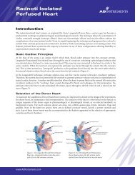
NIBP Controller Owner's Guide - ADInstruments
NIBP Controller Owner's Guide - ADInstruments
NIBP Controller Owner's Guide - ADInstruments

You also want an ePaper? Increase the reach of your titles
YUMPU automatically turns print PDFs into web optimized ePapers that Google loves.
Output socket of the <strong>NIBP</strong> <strong>Controller</strong> allows connection of further<br />
<strong>ADInstruments</strong> front-ends to the system, in series (the input of the next<br />
connects to the output of the previous).<br />
Pressure Signal Output<br />
Connect this output to a PowerLab input channel to record pressure. This<br />
signal is proportional to the cuff pressure and is precalibrated to produce 1 V<br />
per 300 mmHg. By using Units Conversion in LabChart you can easily display<br />
the cuff pressure in mmHg (or similar units).<br />
Pulse Signal Output<br />
Connect this output to a PowerLab input channel to record the pulse. This<br />
pulse signal is used to determine the points at which the pressure signal will<br />
be read to calculate systolic pressures.<br />
Max mmHg Switch<br />
This switch sets the maximum cuff inflation pressure, which will occur<br />
immediately before deflation takes place. Two settings are available: 200 and<br />
280 mmHg.<br />
Gain Adjust<br />
This control allows an increase or decrease in the amplification of the signal<br />
to suit the type of pulse transducer being used. It will have been factory set,<br />
and you should not find it necessary to make further adjustment. The<br />
adjustment of this control is described in Chapter 2.<br />
Trigger In Connector<br />
This trigger connector provides a means to start and stop the <strong>NIBP</strong> measuring<br />
cycle from an external device that is providing a TTL compatible signal. This<br />
input can be connected to the analog output of a PowerLab so that the<br />
LabChart recording software can send a trigger signal (use a 3–5 V pulse<br />
when setting up triggering in LabChart) to start a measurement cycle.<br />
Trigger Out Connector<br />
This connector provides a signal that can be used by the LabChart software to<br />
make data recording take place only during the measurement cycle. This is<br />
useful if you are performing multiple measurement cycles at, say, 30 minute<br />
intervals, and do not want to record the unwanted signals between cycles.<br />
This output is connected to the External Trigger input of a PowerLab. The<br />
signal is TTL compatible (zero or 5 V) and indicates 5 V when a measurement<br />
cycle is taking place.<br />
16<br />
<strong>NIBP</strong> <strong>Controller</strong> Owner’s <strong>Guide</strong>