Higher DC pressure rating 80% reduction in ... - ASCO Valve Inc.
Higher DC pressure rating 80% reduction in ... - ASCO Valve Inc.
Higher DC pressure rating 80% reduction in ... - ASCO Valve Inc.

You also want an ePaper? Increase the reach of your titles
YUMPU automatically turns print PDFs into web optimized ePapers that Google loves.
4<br />
<strong>Higher</strong> <strong>DC</strong> <strong>pressure</strong> <strong>rat<strong>in</strong>g</strong><br />
<strong>80%</strong> <strong>reduction</strong> <strong>in</strong> power consumption<br />
Built-<strong>in</strong> surge suppression<br />
3-year coil warranty<br />
Class I, Division 2 coils available<br />
www.ascovalve.com
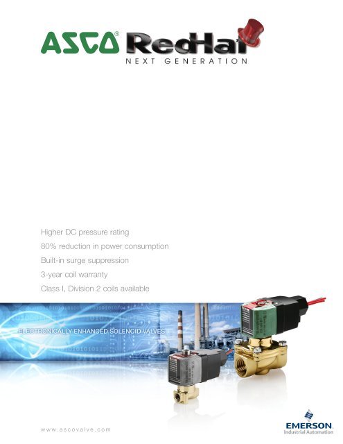
RedHat Next Generation | Electronically Enhanced Solenoid <strong>Valve</strong> Technology<br />
RedHat Next Generation is the future of solenoid valve technology, designed and manufactured to<br />
provide new capabilities. The Next Generation of solenoid valves provides lower ope<strong>rat<strong>in</strong>g</strong> cost, and<br />
represents an advancement <strong>in</strong> the performance, reliability, and ruggedness that you have come to<br />
expect from <strong>ASCO</strong>.<br />
Electronics technology to manage power<br />
RedHat Next Generation valves use electronics technology to manage power, provid<strong>in</strong>g a new standard of operation.<br />
The solenoid <strong>in</strong>corporates a power management circuit provid<strong>in</strong>g lower power consumption, enhanced <strong>pressure</strong> and<br />
flow <strong>rat<strong>in</strong>g</strong>s, and electrical surge suppression to both the solenoid and electronic controls.<br />
Only 2 watts of power<br />
The new solenoid draws only 2 watts of power. A conventional solenoid with the same performance can draw as high as 17<br />
watts of power. The sav<strong>in</strong>gs <strong>in</strong> power usage over the <strong>in</strong>stalled life of the valve will lower the total cost of ownership up to 14%.<br />
<strong>Inc</strong>reased <strong>DC</strong> performance<br />
The new technology accepts both AC and <strong>DC</strong> voltages without sacrific<strong>in</strong>g flow or <strong>pressure</strong> specifications. <strong>DC</strong> performance<br />
has been <strong>in</strong>creased by 150% to 500% from today’s <strong>in</strong>dustry standards, mak<strong>in</strong>g the valves’ <strong>DC</strong> characteristics equivalent to<br />
AC <strong>pressure</strong> and flow values. This simplifies your control by elim<strong>in</strong>at<strong>in</strong>g the need for AC output cards, reduces wir<strong>in</strong>g costs,<br />
and provides safer work<strong>in</strong>g environments for users ope<strong>rat<strong>in</strong>g</strong> on <strong>DC</strong>.<br />
RedHat Next Generation coils are offered <strong>in</strong> three voltage ranges cover<strong>in</strong>g most electrical requirements – 100-240/AC or <strong>DC</strong>,<br />
24-99/AC or <strong>DC</strong>, or 12-24/<strong>DC</strong>. Each coil has built-<strong>in</strong> electrical surge suppression that protects the coil from<br />
external voltage spikes and elim<strong>in</strong>ates <strong>in</strong>ductive voltage spikes associated with<br />
conventional solenoids. An optional solenoid is available for use <strong>in</strong><br />
Class I, Division 2 hazardous locations.<br />
Rugged Design<br />
<strong>ASCO</strong> RedHat Next Generation addresses many other ope<strong>rat<strong>in</strong>g</strong><br />
characteristics that will further improve the life of your solenoid<br />
valves. These <strong>in</strong>clude a much lower temperature rise, and an<br />
<strong>in</strong>crease <strong>in</strong> valve ambient temperature <strong>rat<strong>in</strong>g</strong> to 140˚F/60˚C.<br />
Because of our confidence <strong>in</strong> the rugged design of the RedHat<br />
Next Generation solenoids, <strong>ASCO</strong> is pleased to extend a 3-year<br />
warranty on the coils.<br />
Visit us onl<strong>in</strong>e at www.ascovalve.com to see our comprehensive product portfolio.
4<br />
• 1/2 <strong>in</strong>ch female conduit<br />
• Polyester coated alum<strong>in</strong>um conduit hub<br />
• Enclosure Types 1 through 4X<br />
• Now standard with 24 <strong>in</strong>ch leads<br />
• Sta<strong>in</strong>less steel nameplate<br />
• Steel clip with epoxy powder coated pa<strong>in</strong>t<br />
• LCP overmolded coil<br />
• Optional Class I, Division 2 coil available<br />
for hazardous locations
VALVE SELECTION & ORDERING<br />
As you use this catalog to select RedHat Next Generation products, note these key ope<strong>rat<strong>in</strong>g</strong> features:<br />
• <strong>Inc</strong>rease <strong>in</strong> <strong>DC</strong> <strong>pressure</strong> <strong>rat<strong>in</strong>g</strong>s to AC levels on all products (up to a 500% improvement)<br />
• Lower power operation<br />
• Voltage rang<strong>in</strong>g<br />
• Built <strong>in</strong> surge suppression<br />
• Elim<strong>in</strong>ation of AC hum<br />
• <strong>Inc</strong>rease <strong>in</strong> AC and <strong>DC</strong> ope<strong>rat<strong>in</strong>g</strong> temperatures<br />
• Low solenoid temperature rise<br />
• Longer coil life due to lower ope<strong>rat<strong>in</strong>g</strong> temperatures and electrical surge suppression<br />
• Solenoid approvals to UL, CSA, and CE standards<br />
How to order<br />
F<strong>in</strong>d the valve that you are look<strong>in</strong>g for <strong>in</strong> the provided specifications tables. The tables conta<strong>in</strong> the follow<strong>in</strong>g<br />
<strong>in</strong>formation designed to help you <strong>in</strong> mak<strong>in</strong>g your selection:<br />
Pipe<br />
Size<br />
(<strong>in</strong>)<br />
Orifice<br />
Dia.<br />
(<strong>in</strong>)<br />
Cv<br />
Flow<br />
Ope<strong>rat<strong>in</strong>g</strong> Pressure<br />
Differential (psi)<br />
Max. AC/<strong>DC</strong><br />
Agency<br />
Agency<br />
Air-Inert<br />
Gas Water<br />
Light Oil<br />
@ 300 SSU<br />
Max Fluid<br />
Temp.˚F<br />
Brass<br />
1<br />
Const.<br />
Ref. UL<br />
Sta<strong>in</strong>less<br />
Steel<br />
Const.<br />
Ref. UL<br />
1 When order<strong>in</strong>g a valve product, specify the <strong>ASCO</strong> base catalog number (Ex. 8210P094).<br />
This number will always be 8 digits long.<br />
Choose one of the three ope<strong>rat<strong>in</strong>g</strong> voltage ranges (100-240V/50-60Hz/<strong>DC</strong>, 24-99V/50-60Hz/<strong>DC</strong> or 12-24/<strong>DC</strong>)<br />
and add it to the base catalog number (Ex. 8210P094 24-99V/50-60Hz/<strong>DC</strong>).<br />
If you want to enhance the product with one or more of the options allowed <strong>in</strong> the Optional Features Chart for that<br />
catalog number, please add the appropriate prefix or suffix (as shown):<br />
➁ Optional Class I, Division 2 solenoid (Ex. EE8210P094 24-99V/50-60Hz/<strong>DC</strong>)<br />
➂ If an FKM elastomer and manual operator are required, add VMO to the back of the base catalog number.<br />
(Ex. 8210P094VMO 24-99V/50-60Hz/<strong>DC</strong>)<br />
➃ When order<strong>in</strong>g a rebuild kit for a valve, supply the rebuild kit number as shown <strong>in</strong> the table. (Ex. 322670)<br />
When order<strong>in</strong>g a rebuild kit for a valve with a suffix, add the suffix to the appropriate standard rebuild kit.<br />
(Ex. The rebuild kit for the above valve with FKM is 322670-V)<br />
All constructions are available with prefix EE for Class I, Division 2 requirements.<br />
When order<strong>in</strong>g a replacement coil, select from the follow<strong>in</strong>g:<br />
Warn<strong>in</strong>g: Improper selection or use of products and related items <strong>in</strong> this catalog can cause death, serious <strong>in</strong>jury or property damage.<br />
If you need any assistance <strong>in</strong> select<strong>in</strong>g, specify<strong>in</strong>g, or order<strong>in</strong>g a valve, please contact <strong>ASCO</strong> at (800) 972-2726.<br />
w w w . a s c o v a l v e . c o m<br />
Wattage<br />
AC/<strong>DC</strong><br />
Approx.<br />
Shipp<strong>in</strong>g<br />
Weight (lbs.)<br />
M<strong>in</strong>.<br />
1/2 5/8 4 0 150 150 - 180 8210P094 4 ❍ - - - 2 3.2<br />
Pipe<br />
Size<br />
(<strong>in</strong>)<br />
Orifice<br />
Dia.<br />
(<strong>in</strong>)<br />
Solenoid Options ➁ Base Catalog Number Resilient Materials ➂ Other ➂ Standard Rebuild Kit ➃<br />
Class I,<br />
Division 2 Coil<br />
Brass<br />
Sta<strong>in</strong>less Steel<br />
NBR<br />
FKM<br />
1/2 5/8 EE 8210P094 - ● V E J N - - VH MO MB 322670 -<br />
Solenoid Enclosures<br />
Standard: Watertight, Types 1, 2, 3, 3S, 4, and 4X.<br />
Optional: Class I, Division 2 for Hazardous Locations and Watertight, Types 3, 3S, 4, 4X.<br />
(To order, add prefix “EE” to catalog number.)<br />
Voltage Range <strong>Valve</strong> Prefix Replacement Coil Part Number<br />
100-240V/50-60Hz/<strong>DC</strong> - 250404-601-*<br />
24-99V/50-60Hz/<strong>DC</strong> - 250404-602-*<br />
12-24/<strong>DC</strong> - 250404-603-*<br />
100-240V/50-60Hz/<strong>DC</strong> EE 250504-601-*<br />
24-99V/50-60Hz/<strong>DC</strong> EE 250504-602-*<br />
12-24/<strong>DC</strong> EE 250504-603-*<br />
EPDM<br />
CR<br />
Oxygen Service<br />
PTFE<br />
Urethane<br />
Vacuum<br />
Manual Operator<br />
Mount<strong>in</strong>g Bracket<br />
Brass AC/<strong>DC</strong><br />
Sta<strong>in</strong>less Steel<br />
AC/<strong>DC</strong>
4<br />
NEXT GENERATION | CONTENTS<br />
2-Way <strong>Valve</strong>s<br />
2-Way Normally Closed 1-2<br />
2-Way Normally Open 1-2<br />
2-Way Dimensional Draw<strong>in</strong>gs 3-4<br />
3-Way <strong>Valve</strong>s<br />
3-Way Normally Closed 5-6<br />
3-Way Normally Open 5-6<br />
3-Way Universal 5-6<br />
3-Way Dimensional Draw<strong>in</strong>gs 7-8<br />
4-Way <strong>Valve</strong>s 9<br />
Dimensional Draw<strong>in</strong>gs 10<br />
Eng<strong>in</strong>eer<strong>in</strong>g Information 12-18<br />
w w w . a s c o v a l v e . c o m
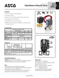
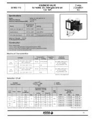
2-WAY | Solenoid <strong>Valve</strong>s<br />
4<br />
• Two-way (2/2) Next Generation solenoid valves have one <strong>in</strong>let<br />
port and one outlet port.<br />
• Control of air, water, light oil, and non-corrosive media.<br />
• Normally closed (opens when energized) and normally<br />
open (closed when energized) operation.<br />
• Pipe sizes – 1/8 to 2 <strong>in</strong>ch.<br />
1<br />
Specifications<br />
Pipe Orifice<br />
Ope<strong>rat<strong>in</strong>g</strong> Pressure Differential (psi)<br />
Max. AC/<strong>DC</strong><br />
Max<br />
Agency<br />
Agency<br />
Size<br />
(<strong>in</strong>)<br />
Dia.<br />
(<strong>in</strong>)<br />
Cv<br />
Flow M<strong>in</strong>.<br />
Air-Inert<br />
Gas Water<br />
Light Oil<br />
@ 300 SSU<br />
Fluid<br />
Temp.˚F Brass<br />
Const.<br />
Ref. UL Sta<strong>in</strong>less Steel Const. Ref. UL<br />
Wattage<br />
AC/<strong>DC</strong><br />
General Service - Normally Closed<br />
1/8 3/64 0.06 0 2200 2200 1700 140 - - - 8262R175 ➄ 1 ● 2<br />
1/8 3/64 0.06 0 1500 1500 1500 140 8262R099 ➄ 1 ● - - - 2<br />
1/8 3/32 0.21 0 720 410 410 180 8262R277 1 ❍ 8262R178 1 ❍ 2<br />
1/8 1/8 0.35 0 540 395 360 180 8262R105 1 ❍ 8262R174 1 ❍ 2<br />
1/8 1/8 0.35 0 200 - - 167 8262R077 ➅ 1 ❍ - - - 2<br />
1/4 3/64 0.06 0 1500 1500 1500 140 8262R107 ➄ 2 ● - - - 2<br />
1/4 3/64 0.06 0 2200 2200 1700 140 - - - 8262R181 ➄ 2 ● 2<br />
1/4 3/32 0.21 0 720 410 410 180 8262R109 2 ❍ 8262R183 2 ❍ 2<br />
1/4 1/8 0.35 0 540 395 360 180 8262R232 2 ❍ 8262R185 2 ❍ 2<br />
1/4 5/32 0.52 0 300 225 225 180 8262R202 2 ❍ 8262R220 2 ❍ 2<br />
1/4 7/32 0.73 0 125 125 125 180 8262R208 2 ❍ 8262R226 2 ❍ 2<br />
1/4 9/32 0.88 0 105 105 105 180 8262R212 2 ❍ 8262R230 2 ❍ 2<br />
1/4 9/32 1.0 0 50 - - 167 8262R078 ➅ 2 ❍ - - - 2<br />
1/4 5/16 1.5 10 1500 1500 1500 180 8223P025 18 - - - - 2<br />
3/8 1/8 0.35 0 540 395 360 180 8263R115 3 ❍ 8263R191 3 ❍ 2<br />
3/8 5/32 0.52 0 300 225 225 180 8263R200 3 ❍ 8263R193 3 ❍ 2<br />
3/8 7/32 0.73 0 125 125 125 180 8263R124 3 ❍ 8263R332 3 ❍ 2<br />
3/8 9/32 0.88 0 105 85 85 180 8263R210 3 ❍ 8263R333 3 ❍ 2<br />
3/8 5/16 1.5 10 1500 1500 1500 180 8223P027 18 - - - - 2<br />
3/8 5/8 3 0 150 150 - 180 8210P093 4 ❍ - - - 2<br />
3/8 5/8 3 5 300 300 300 180 8210P006 4 ● - - - 2<br />
1/2 3/8 3.2 25 1500 1500 1500 180 8223P003 5 - 8223P010 6 - 2<br />
1/2 5/8 4 0 150 150 - 180 8210P094 4 ❍ - - - 2<br />
1/2 5/8 4 0 150 150 125 180 - - - 8210P087 7 ● 2<br />
1/2 5/8 4 5 300 300 300 180 8210P007 4 ❍ - - - 2<br />
3/4 5/8 4.5 0 150 150 125 180 - - - 8210P088 7 ● 2<br />
3/4 3/4 5 0 150 150 - 180 8210P095 7 ❍ - - - 2<br />
3/4 3/4 5 0 3 3 - 180 8030P003 8 ❍ - - - 2<br />
3/4 3/4 7.8 25 750 750 750 180 8223P005 9 - - - - 2<br />
1 1 13 5 150 150 100 180 8210P004 10 ❍ - - - 2<br />
1 1/4 1 1/8 15 5 150 150 100 180 8210P008 10 ❍ - - - 2<br />
1 1/2 1 1/4 22.5 5 150 150 100 180 8210P022 11 ❍ - - - 2<br />
2 1 3/4 43 5 150 125 90 180 8210P100 12 ● - - - 2<br />
General Service - Normally Open<br />
1/8 3/64 0.06 0 1150 900 800 140 8262R155 ➄ 13 ● 8262R168 ➄ 13 ● 2<br />
1/8 3/64 0.06 0 750 750 750 180 8262R156 13 ● 8262R169 13 ● 2<br />
1/8 3/32 0.21 0 275 230 180 180 8262R128 13 ● 8262R236 13 ● 2<br />
1/8 1/8 0.35 0 160 145 125 180 8262R129 13 ● 8262R237 13 ● 2<br />
1/4 3/64 0.06 0 1150 900 800 140 8262R161 ➄ 14 ● 8262R199 ➄ 14 ● 2<br />
1/4 3/64 0.06 0 750 750 750 180 8262R260 14 ● 8262R130 14 ● 2<br />
1/4 3/32 0.21 0 275 230 180 180 8262R261 14 ● 8262R134 14 ● 2<br />
1/4 1/8 0.35 0 160 145 125 180 8262R262 14 ● 8262R138 14 ● 2<br />
1/4 5/32 0.54 0 90 90 70 180 8262R263 14 ● 8262R142 14 ● 2<br />
1/4 7/32 0.83 0 45 45 40 180 8262R264 14 ● 8262R148 14 ● 2<br />
1/4 9/32 0.96 0 30 30 30 180 8262R265 14 ● 8262R152 14 ● 2<br />
3/8 1/8 0.35 0 160 145 125 180 8263R070 18 ● 8263R080 18 ● 2<br />
3/8 5/32 0.54 0 90 90 70 180 8263R071 18 ● 8263R081 18 ● 2<br />
3/8 7/32 0.83 0 45 45 40 180 8263R072 18 ● 8263R082 18 ● 2<br />
3/8 9/32 0.96 0 30 30 30 180 8263R073 18 ● 8263R083 18 ● 2<br />
3/8 5/8 3 0 150 150 125 180 8210P033 15 ● - - - -<br />
1/2 5/8 4 0 150 150 125 180 8210P034 15 ● - - - -<br />
3/4 3/4 5.5 0 150 150 125 180 8210P035 16 ● - - - -<br />
3/4 3/4 5.5 0 2 2 - 180 8030P083 17 ● - - - -<br />
❍ = Safety Shut-off <strong>Valve</strong>. ● = General Purpose <strong>Valve</strong>.<br />
w w w . a s c o v a l v e . c o m
4<br />
2-WAY | Solenoid <strong>Valve</strong>s<br />
Pipe<br />
Size<br />
(<strong>in</strong>)<br />
Orifice<br />
Dia.<br />
(<strong>in</strong>)<br />
Base Catalog Number Resilient Materials and Suffix Options Other Standard Rebuild Kit<br />
Brass<br />
Sta<strong>in</strong>less Steel<br />
Ammonia ➆<br />
Optional Features Chart<br />
Silicone Free<br />
Dry Air<br />
NBR<br />
LT NBR<br />
FKM<br />
1/8 3/64 8262R099 ➄ 8262R175 ➄ - SF - - - - - - - - ● - - MB 323593-W 323595-W<br />
1/8 3/64 8262R155 ➄ 8262R168 ➄ - SF - - - - - - - - ● - - MB 323986-W 323988-W<br />
1/8 3/64 8262R156 8262R169 NH SF - ● A V E J N T - - MS MB 323986 323988<br />
1/8 3/32 8262R277 8262R178 NH SF - ● A V E J N T - MS MB 323593 323595<br />
1/8 3/32 8262R128 8262R236 NH SF - ● A V E J N T - - MS MB 323987 323989<br />
1/8 1/8 8262R105 8262R174 NH SF - ● A V E J N T - VH MS MB 323593 323595<br />
1/8 1/8 8262R077 ➅ - - SF - - ● - - - - - - - - MB 325039 -<br />
1/8 1/8 8262R129 8262R237 NH SF - ● A V E J N T - VH MS MB 323987 323989<br />
1/4 3/64 8262R107 ➄ 8262R181 ➄ - - - - - - - - - - ● - - MB 323593-W 323595-W<br />
1/4 3/64 8262R161 ➄ 8262R199 ➄ - SF - - - - - - - - ● - - MB 323986-W 323988-W<br />
1/4 3/64 8262R260 8262R130 NH SF - ● A V E J N T - - MS MB 323986 323988<br />
1/4 3/32 8262R109 8262R183 NH SF P ● A V E J N T - - MS MB 323593 323595<br />
1/4 3/32 8262R261 8262R134 NH SF - ● A V E J N T - - MS MB 323987 323989<br />
1/4 1/8 8262R232 8262R184 NH SF P ● A V E J N T - - MS MB 323593 323595<br />
1/4 1/8 8262R262 8262R138 NH SF - ● A V E J N T - - MS MB 323987 323989<br />
1/4 5/32 8262R202 8262R220 NH SF P ● A V E J N T - - MS MB 323593 323595<br />
1/4 5/32 8262R263 8262R142 NH SF - ● A V E J N T - - MS MB 323987 323989<br />
1/4 7/32 8262R208 8262R226 NH SF P ● A V E J N T - - MS MB 323593 323595<br />
1/4 7/32 8262R264 8262R148 NH SF - ● A V E J N T - - MS MB 323987 323989<br />
1/4 9/32 8262R212 8262R230 NH SF P ● A V E J N T - VH MS MB 323593 323595<br />
1/4 9/32 8262R265 8262R152 NH SF - ● A V E J N T - VH MS MB 323987 323989<br />
1/4 9/32 8262R078 ➅ - - SF - - ● - - - - - - - - MB 325039 -<br />
1/4 5/16 8223P025 ➃ - - - - ● A - - - - - - - - - 322815 -<br />
3/8 1/8 8263R115 8263R191 NH SF - ● A V E J N T - - MS MB 323593 323595<br />
3/8 1/8 8263R070 8263R080 NH SF - ● A V E J N T - - MS MB 323987 323989<br />
3/8 5/32 8263R200 8263R193 NH SF - ● A V E J N T - - MS MB 323593 323595<br />
3/8 5/32 8263R071 8263R081 NH SF - ● A V E J N T - - MS MB 323987 323989<br />
3/8 7/32 8263R124 8263R332 NH SF - ● A V E J N T - - MS MB 323593 323595<br />
3/8 7/32 8263R072 8263R082 NH SF - ● A V E J N T - - MS MB 323987 323989<br />
3/8 9/32 8263R210 8263R333 NH SF - ● A V E J N T - - MS MB 323593 323595<br />
3/8 9/32 8263R073 8263R083 NH SF - ● A V E J N T - - MS MB 323987 323989<br />
3/8 5/16 8223P027 ➃ - - - - ● - - - - - - - - - - 322815 -<br />
3/8 5/8 8210P093 - - - - ● - V E J N - - VH MO MB 322670 -<br />
3/8 5/8 8210P033 - - - - ● - V E J N - - VH - MB 322770 -<br />
3/8 5/8 8210P006 - - - - ● - V E J N - - - MO MB 322654 -<br />
1/2 3/8 8223P003 ➃ 8223P010 1 - - - ● - - - - - - - - - - 322816 322817<br />
1/2 5/8 8210P094 - - - - ● - V E J N - - VH MO MB 322670 -<br />
1/2 5/8 8210P034 - - - - ● - V E J N - - VH - MB 322770 -<br />
1/2 5/8 - 8210P087 - - - ● - V E J N - - - MO MB - 322676<br />
1/2 5/8 8210P007 - - - - ● - V E J N - - - MO ➂ MB 322654 -<br />
3/4 5/8 - 8210P088 - - - ● - V E J N - - - MO MB - 322676<br />
3/4 3/4 8210P095 - - - - ● - V E J N - - VH MO MB 322673 -<br />
3/4 3/4 8030P003 - - - - ● - V E J N - - - MO MB 322758 -<br />
3/4 3/4 8210P035 - - - - ● - V E J N - - VH - MB 322771 -<br />
3/4 3/4 8030P083 - - - - ● - V E J N - - - - MB 322763 -<br />
3/4 3/4 8223P005 ➃ - - - - ● - - - - - - - - - - 322818 -<br />
1 1 8210P004 - - - - ● - V E J N - - - MO - 322677 -<br />
1 1/4 1 1/8 8210P008 - - - - ● - V E J N - - - MO - 322680 -<br />
1 1/2 1 1/4 8210P022 - - - - ● - V E J N - - - MO - 322680 -<br />
2 1 3/4 8210P100 - - - - ● - V E J N - - - MO - 322682 -<br />
● = Standard. Other options may be available. All option comb<strong>in</strong>ations may not be available. Please consult your local <strong>ASCO</strong> contact.<br />
1 <strong>Valve</strong> conta<strong>in</strong>s PTFE ma<strong>in</strong> disc; ➁ Pressure <strong>rat<strong>in</strong>g</strong> reduced by 25%; ➂ Pressure <strong>rat<strong>in</strong>g</strong> limited to 250 psi; ➃ <strong>Valve</strong> conta<strong>in</strong>s Nylon 11 piston.<br />
➄ Cast UR disc supplied as standard, limits m<strong>in</strong>. ambient temp. to 32˚F (0˚C). ➅ Fuel gas service only; Ambient Temp. -40˚F to 140˚F, Fluid Temp. -40˚F to 167˚F; Gas capacity<br />
for 8262R077 is 18,700 Btu/hr, for 8262R078 53,500 Btu/hr based on 1" W.C. Drop @ 2" W.C. Inlet Pressure, 1000 Btu/cu.ft. or more, 0.64 Specific Gravity Gas.<br />
➆ NH suffix only available for Sta<strong>in</strong>less Steel constructions.<br />
EPDM<br />
CR<br />
Oxygen Service<br />
PTFE ➁<br />
Urethane<br />
Vacuum<br />
Manual<br />
Operator<br />
Mount<strong>in</strong>g<br />
Bracket<br />
Brass AC/<strong>DC</strong><br />
Sta<strong>in</strong>less Steel<br />
AC/<strong>DC</strong><br />
w w w . a s c o v a l v e . c o m<br />
2
2-WAY | Solenoid <strong>Valve</strong>s<br />
4<br />
Dimensions: <strong>in</strong>ches<br />
Const.<br />
Ref. B C D E F G H I<br />
1 3.98 3.04 2.00 0.69 1.00 1.19 1.87 1.24<br />
2 3.98 3.04 2.00 0.78 1.11 1.56 1.87 1.29<br />
3 3.98 3.04 2.00 0.77 1.20 1.88 1.87 1.25<br />
4 3.98 3.04 2.00 1.28 1.84 2.75 1.87 2.28<br />
5 3.98 3.04 2.00 1.05 2.31 - 1.87 3.03<br />
6 3.98 3.04 2.00 1.13 2.31 - 1.87 3.13<br />
7 3.98 3.04 2.00 1.46 2.19 2.81 1.87 2.28<br />
8 3.98 3.04 2.00 1.44 2.13 2.81 1.87 2.28<br />
9 3.98 3.04 2.00 1.61 3.03 - 1.87 3.6<br />
10 3.98 3.04 2.00 2.21 3.67 3.75 1.87 -<br />
11 3.98 3.04 2.00 2.36 4.14 4.38 1.87 3.92<br />
12 3.98 3.04 2.00 2.75 5.52 5.06 1.87 4.72<br />
13 3.98 3.04 2.00 0.69 1.00 1.19 1.87 1.24<br />
14 3.98 3.04 2.00 0.78 1.11 1.56 1.87 1.29<br />
15 3.98 3.04 2.00 1.72 2.18 2.75 1.87 2.28<br />
16 3.98 3.04 2.00 1.88 2.57 2.81 1.87 2.28<br />
17 3.98 3.04 2.00 0.85 1.81 2.81 1.87 2.28<br />
18 3.98 3.04 2.00 0.77 1.20 1.88 1.87 1.25<br />
.3<br />
[8]<br />
.7<br />
[17.5]<br />
MOUNTING HOLES<br />
G<br />
FLOW<br />
Const. Ref.1<br />
B<br />
C<br />
D<br />
E<br />
F<br />
ANPT<br />
BOTH ENDS<br />
.6<br />
[15]<br />
MOUNTING HOLES<br />
M5 THREAD<br />
.30 [7.6] MIN. FULL THREAD<br />
DEPTH.<br />
2 HOLES FOR MOUNTING.<br />
H<br />
I<br />
Const. Ref.2<br />
Const. Ref. 3<br />
B<br />
B<br />
C<br />
H<br />
C<br />
H<br />
D<br />
D<br />
E<br />
F<br />
E<br />
F<br />
G<br />
ANPT<br />
BOTH ENDS<br />
I<br />
G<br />
ANPT<br />
BOTH ENDS<br />
I<br />
.34<br />
[9]<br />
.87<br />
[22.2]<br />
MOUNTING HOLES<br />
.57<br />
[14]<br />
.75<br />
[19]<br />
MOUNTING HOLES<br />
.87<br />
[22.2]<br />
MOUNTING HOLES<br />
.81<br />
[20.6]<br />
MOUNTING HOLES<br />
FLOW<br />
M5 THREAD<br />
.30 [7.6] MIN. FULL THREAD<br />
DEPTH.<br />
2 HOLES FOR MOUNTING.<br />
FLOW<br />
M5 THREAD<br />
.24 [6] MIN. FULL THREAD DEPTH.<br />
2 HOLES FOR MOUNTING<br />
Const. Ref. 4, 7, 15, 16, 17<br />
Const. Ref. 5, 6, 9<br />
B<br />
C<br />
H<br />
1/2 NPT<br />
B<br />
C<br />
H<br />
1/2 NPT<br />
D<br />
E<br />
F<br />
F<br />
E<br />
G<br />
I<br />
I<br />
3<br />
w w w . a s c o v a l v e . c o m
4<br />
2-WAY | Solenoid <strong>Valve</strong>s<br />
Dimensions: <strong>in</strong>ches<br />
Const. Ref. 8<br />
Const. Ref. 10<br />
B<br />
B<br />
C<br />
H<br />
1/2 NPT<br />
C<br />
H<br />
1/2 NPT<br />
D<br />
D<br />
E<br />
F<br />
E<br />
F<br />
G<br />
I<br />
G<br />
Const. Ref. 11, 12<br />
Const. Ref. 13, 14<br />
B<br />
C<br />
H<br />
1/2 NPT<br />
B<br />
C<br />
H<br />
1/2 NPT<br />
D<br />
D<br />
E<br />
E<br />
F<br />
F<br />
.67 I<br />
I<br />
G<br />
2 MOUNTING HOLES<br />
.31 DEEP FOR .164<br />
THREAD CUTTING SCREW<br />
Const. Ref. 18<br />
C<br />
B<br />
H<br />
1/2 NPT<br />
D<br />
E<br />
F<br />
G<br />
w w w . a s c o v a l v e . c o m<br />
4
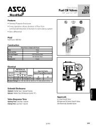
3-WAY | Solenoid <strong>Valve</strong>s<br />
4<br />
• Three-way (3/2) Next Generation solenoid valves have three ports and<br />
two orifices. When one orifice is open, the other is closed.<br />
• Control of air, water, light oil, and other non-corrosive media.<br />
• Normally closed (<strong>pressure</strong> to cyl<strong>in</strong>der port when energized) operation.<br />
• Normally open (cyl<strong>in</strong>der port exhausts when energized) operation.<br />
• Universal operation (can function as normally open, normally<br />
closed, diverter of fluid flow, or selector of 2 fluid sources<br />
configurable by pip<strong>in</strong>g).<br />
• Pipe sizes – 1/4 to 3/4 <strong>in</strong>ch.<br />
5<br />
Specifications<br />
Pipe Orifice<br />
Ope<strong>rat<strong>in</strong>g</strong> Pressure<br />
Differential (psi)<br />
Max. AC/<strong>DC</strong><br />
Max.<br />
Agency<br />
Agency<br />
Approx.<br />
Size<br />
(<strong>in</strong>)<br />
Dia.<br />
(<strong>in</strong>)<br />
Cv<br />
Flow M<strong>in</strong>.<br />
Air-Inert<br />
Gas Water<br />
Light Oil<br />
@ 300 SSU<br />
Fluid<br />
Temp.˚F Brass<br />
Const.<br />
Ref. UL Sta<strong>in</strong>less Steel<br />
Const.<br />
Ref. UL<br />
Wattage<br />
AC/<strong>DC</strong><br />
Shipp<strong>in</strong>g<br />
Weight (lbs.)<br />
General Service - Normally Closed<br />
1/8 3/64 0.05 ➂ 0 300 300 300 7 200 ➅ 8314R031 1 ● 8314R037 1 ● 2 1.7<br />
1/8 3/32 0.15 ➃ 0 205 205 190 7 200 ➅ 8314R032 1 ● 8314R038 1 ● 2 1.7<br />
1/8 1/8 0.25 ➃ 0 145 145 100 7 200 ➅ 8314R033 1 ● 8314R039 1 ● 2 1.7<br />
1/4 3/64 0.05 ➂ 0 300 300 300 7 200 ➅ 8314R034 2 ● 8314R068 2 ● 2 1.8<br />
1/4 3/32 0.15 ➃ 0 205 205 190 7 200 ➅ 8314R035 2 ● 8314R121 2 ● 2 1.8<br />
1/4 1/8 0.25 ➃ 0 145 145 100 7 200 ➅ 8314R036 2 ● 8314R126 2 ● 2 1.8<br />
1/4 5/32 0.50 ➃ 0 75 75 75 7 200 ➅ 8314R130 2 ● 8314R230 2 ● 2 1.8<br />
1/4 7/32 0.70 ➃ 0 40 40 40 7 200 ➅ 8314R131 2 ● 8314R231 2 ● 2 1.8<br />
1/4 9/32 0.85 ➃ 0 25 25 25 7 200 ➅ 8314R132 2 ● 8314R232 2 ● 2 1.8<br />
1/4 5/64 0.12 0 232 232 232 180 8320P182 3 ● - - - 2 2.5<br />
1/4 7/64 0.23 0 150 150 150 180 8320P184 3 ● - - - 2 2.5<br />
1/4 5/32 0.35 0 75 75 75 180 8320P186 3 ● - - - 2 2.5<br />
1/4 3/32 1 0.2 1 5 ➄ 150 150 100 180 8317P035 4 ● - - - 2 2.7<br />
1/4 9/32 ➁ 0.8 ➁ 10 200 200 200 180 8321P001 5 ● - - - 2 3.8<br />
3/8 9/32 ➁ 0.8 ➁ 10 200 200 200 180 8321P002 5 ● - - - 2 3.8<br />
3/8 5/8 2.5 10 250 250 - 180 8316P054 6 ● - - - 2 4.9<br />
1/2 5/8 3.2 10 250 250 - 180 8316P064 6 ● - - - 2 4.9<br />
3/4 11/16 4.8 10 250 250 - 180 8316P074 7 ● - - - 2 5.1<br />
NAMUR Mount - 3/2 Normally Closed<br />
1/4 3/32 0.12 - 150 - - 180 8320P704 9 ● 8320P714 9 ● 2 3.2<br />
General Service - Normally Open<br />
1/8 3/64 0.05 ➂ 0 300 300 300 7 200 ➅ 8314R049 1 ● 8314R055 1 ● 2 1.7<br />
1/8 3/32 0.15 ➃ 0 175 175 175 7 200 ➅ 8314R050 1 ● 8314R056 1 ● 2 1.7<br />
1/8 1/8 0.25 ➃ 0 160 160 160 7 200 ➅ 8314R051 1 ● 8314R057 1 ● 2 1.7<br />
1/4 3/64 0.05 ➂ 0 300 300 300 7 200 ➅ 8314R052 2 ● 8314R069 2 ● 2 1.8<br />
1/4 3/32 0.15 ➃ 0 175 175 175 7 200 ➅ 8314R053 2 ● 8314R122 2 ● 2 1.8<br />
1/4 1/8 0.25 ➃ 0 160 160 160 7 200 ➅ 8314R054 2 ● 8314R070 2 ● 2 1.8<br />
1/4 5/32 0.50 ➃ 0 150 150 150 7 200 ➅ 8314R133 2 ● 8314R233 2 ● 2 1.8<br />
1/4 7/32 0.70 ➃ 0 100 100 100 7 200 ➅ 8314R134 2 ● 8314R234 2 ● 2 1.8<br />
1/4 9/32 0.85 ➃ 0 65 65 65 7 200 ➅ 8314R135 2 ● 8314R235 2 ● 2 1.8<br />
1/8 3/64 0.18 - 350 350 350 180 8320P136 8 ● 8320P146 8 ● 2 2.5<br />
1/4 1/32 0.05 - 790 825 825 180 8320P190 3 ● - - - 2 2.5<br />
1/4 5/64 0.12 0 210 210 210 180 8320P192 3 ● - - - 2 2.5<br />
1/4 7/64 0.23 0 150 150 150 180 8320P194 3 ● - - - 2 2.5<br />
General Service - Universal Operation<br />
1/8 3/64 0.05 ➂ 0 200 200 200 7 200 ➅ 8314R041 1 ● 8314R042 1 ● 2 1.7<br />
1/8 3/32 0.15 ➃ 0 105 85 60 7 200 ➅ 8314R043 1 ● 8314R044 1 ● 2 1.7<br />
1/8 1/8 0.25 ➃ 0 70 70 40 7 200 ➅ 8314R045 1 ● 8314R040 1 ● 2 1.7<br />
1/4 3/64 0.05 ➂ 0 200 200 200 7 200 ➅ 8314R006 2 ● 8314R123 2 ● 2 1.8<br />
1/4 3/32 0.15 ➃ 0 105 85 60 7 200 ➅ 8314R007 2 ● 8314R120 2 ● 2 1.8<br />
1/4 1/8 0.25 ➃ 0 70 70 40 7 200 ➅ 8314R008 2 ● 8314R124 2 ● 2 1.8<br />
1/4 5/32 0.50 ➃ 0 35 35 35 7 200 ➅ 8314R127 2 ● 8314R227 2 ● 2 1.8<br />
1/4 7/32 0.70 ➃ 0 18 18 18 7 200 ➅ 8314R128 2 ● 8314R228 2 ● 2 1.8<br />
1/4 9/32 0.85 ➃ 0 10 10 10 7 200 ➅ 8314R129 2 ● 8314R229 2 ● 2 1.8<br />
1/4 5/64 0.12 0 116 116 116 180 8320P172 3 ● - - - 2 2.5<br />
1/4 7/64 0.23 0 60 60 60 180 8320P174 3 ● - - - 2 2.5<br />
1/4 5/32 0.35 0 35 35 35 180 8320P176 3 ● - - - 2 2.5<br />
● = General Purpose <strong>Valve</strong>. 1 1/4" exhaust orifice with 0.73 Cv flow; ➁ 11/32" exhaust orifice with 1.20 Cv flow; ➂ 3/64" exhaust orifice with 0.06 Cv flow.<br />
➃ 3/32" exhaust orifice with 0.20 Cv flow. ➄ 10 psi m<strong>in</strong>imum for light oils. ➅ Max. fluid temp. 180˚F for light oil @ 45 SSU. 7 Pressure <strong>rat<strong>in</strong>g</strong> for light oil @ 45 SSU.<br />
w w w . a s c o v a l v e . c o m
4 3-WAY | Solenoid <strong>Valve</strong>s<br />
Optional Features Chart<br />
Base Catalog Number Resilient Materials and Suffix Options Other Standard Rebuild Kit<br />
Pipe<br />
Size<br />
(<strong>in</strong>)<br />
Orifice<br />
Dia.<br />
(<strong>in</strong>)<br />
Brass<br />
Sta<strong>in</strong>less Steel<br />
Silicone Free<br />
NBR<br />
FKM<br />
EPDM<br />
1/8 3/64 8314R031 8314R037 SF ● V ➁ - - N - - - MS MB 323957 323959<br />
1/8 3/64 8314R041 8314R042 SF ● V ➁ - - N - - - MS MB 323961 323963<br />
1/8 3/64 8314R049 8314R055 SF ● V ➁ - - N - - - MS MB 323969 323971<br />
1/8 3/32 8314R032 8314R038 SF ● V ➁ - - N - - - MS MB 323958 323960<br />
1/8 3/32 8314R043 8314R044 SF ● V ➁ - - N - - - MS MB 323966 323968<br />
1/8 3/32 8314R050 8314R056 SF ● V ➁ - - N - - - MS MB 323970 323972<br />
1/8 1/8 8314R033 8314R039 SF ● V ➁ - - N - - - MS MB 323958 323960<br />
1/8 1/8 8314R045 8314R040 SF ● V ➁ - - N - - - MS MB 323966 323968<br />
1/8 1/8 8314R051 8314R057 SF ● V ➁ - - N - - - MS MB 323970 323972<br />
1/8 7/16 8320P136 8320P146 ➄ ● V E J N T - - MO/MS MB 322715 322718<br />
1/4 1/32 8320P190 - ➄ ● V E J N T - - MO/MS MB 322744 -<br />
1/4 3/64 8314R006 8314R123 SF ● V ➁ - - N - - - MS MB 323961 323963<br />
1/4 3/64 8314R034 8314R068 SF ● V ➁ - - N - - - MS MB 323957 323959<br />
1/4 3/64 8314R052 8314R069 SF ● V ➁ - - N - - - MS MB 323969 323971<br />
1/4 5/64 8320P172 - ➄ ● V E J N T - - MO/MS ➃ MB 322721 -<br />
1/4 5/64 8320P182 - ➄ ● V E J N T - - MO/MS MB 322722 -<br />
1/4 5/64 8320P192 - ➄ ● V E J N T - - MO/MS ➃ MB 322723 -<br />
1/4 3/32 8314R007 8314R120 SF ● V ➁ - - N - - - MS MB 323966 323968<br />
1/4 3/32 8314R035 8314R121 SF ● V ➁ - - N - - - MS MB 323958 323960<br />
1/4 3/32 8314R053 8314R122 SF ● V ➁ - - N - - - MS MB 323970 323972<br />
1/4 3/32 8317P035 - ➄ ● V - - N - - - - - 322919 -<br />
1/4 3/32 8320P704 8320P714 ➄ ● V E J N T - - MO/MS - 322821 322823<br />
1/4 7/64 8320P174 - ➄ ● V E J N T - - MO/MS ➃ MB 322721 -<br />
1/4 7/64 8320P184 - ➄ ● V E J N T - - MO/MS MB 322722 -<br />
1/4 7/64 8320P194 - ➄ ● V E J N T - - MO/MS ➃ MB 322723 -<br />
1/4 1/8 8314R008 8314R124 SF ● V ➁ - - N - - - MS MB 323966 323968<br />
1/4 1/8 8314R036 8314R126 SF ● V ➁ - - N - - - MS MB 323958 323960<br />
1/4 1/8 8314R054 8314R070 SF ● V ➁ - - N - - - MS MB 323970 323972<br />
1/4 5/32 8314R127 8314R227 SF ● V ➁ - - N - - - MS MB 323966 323968<br />
1/4 5/32 8314R130 8314R230 SF ● V ➁ - - N - - - MS MB 323958 323960<br />
1/4 5/32 8314R133 8314R233 SF ● V ➁ - - N - - - MS MB 323970 323972<br />
1/4 5/32 8320P176 - ➄ ● V E J N T - - MO/MS ➃ MB 322721 -<br />
1/4 5/32 8320P186 - ➄ ● V E J N T - - MO/MS MB 322722 -<br />
1/4 7/32 8314R128 8314R228 SF ● V ➁ - - N - - - MS MB 323966 323968<br />
1/4 7/32 8314R131 8314R231 SF ● V ➁ - - N - - - MS MB 323958 323960<br />
1/4 7/32 8314R134 8314R234 SF ● V ➁ - - N - - - MS MB 323970 323972<br />
1/4 9/32 8314R129 8314R229 SF ● V ➁ - - N - - - MS MB 323966 323968<br />
1/4 9/32 8314R132 8314R232 SF ● V ➁ - - N - - - MS MB 323958 323960<br />
1/4 9/32 8314R135 8314R235 SF ● V ➁ - - N - - - MS MB 323970 323972<br />
1/4 9/32 8321P001 - ➄ ● V E - - - - - MO/MS - 322688 -<br />
3/8 9/32 8321P002 - ➄ ● V E - - - - - MO/MS - 322688 -<br />
3/8 5/8 8316P054 - ➄ ● V E J N - - - MO MB 322690 -<br />
1/2 5/8 8316P064 - ➄ ● V E J N - - - MO MB 322690 -<br />
3/4 11/16 8316P074 - ➄ ● V E J N - - - MO MB 322692 -<br />
● = Standard. Other options may be available. All option comb<strong>in</strong>ations may not be available. Please consult your local <strong>ASCO</strong> contact. 1 Pressure <strong>rat<strong>in</strong>g</strong> reduced by 25%.<br />
➁ Upper disc is FKM. ➂ Not available with PTFE resilient materials. ➃ Pressure <strong>rat<strong>in</strong>g</strong> limited to 100 psi (6.9 bar) for MO constructions. ➄ Consult factory.<br />
CR<br />
Oxygen Service<br />
PTFE 1<br />
Urethane<br />
w w w . a s c o v a l v e . c o m<br />
6<br />
Vacuum<br />
Manual Operator ➂<br />
Mount<strong>in</strong>g Bracket<br />
Brass AC/<strong>DC</strong><br />
Sta<strong>in</strong>less Steel<br />
AC/<strong>DC</strong>
3-WAY | Solenoid <strong>Valve</strong>s<br />
4<br />
Dimensions: <strong>in</strong>ches<br />
Const.<br />
Ref. B C D E F G H I J<br />
1 3.98 3.04 2.09 0.69 1.00 1.19 1.87 1.24 -<br />
2 3.98 3.04 2.09 0.79 1.19 1.56 1.87 1.29 -<br />
3 3.98 3.04 2.00 1.02 2.02 1.69 1.87 1.45 0.44<br />
4 3.98 3.04 2.00 0.57 1.07 2.00 1.87 2.05 -<br />
5 3.98 3.04 2.00 1.00 2.03 1.31 1.87 3.12 1.00<br />
6 3.98 3.04 2.00 2.12 3.77 2.76 1.87 4.29 -<br />
7 3.98 3.04 2.00 2.5 4.19 - 1.87 3.38 -<br />
8 3.98 3.04 2.00 0.67 1.64 1.19 1.87 - 1.81<br />
Const. Ref.1, 2<br />
B<br />
1/8 PIPE<br />
THREAD<br />
C<br />
H<br />
3<br />
CONDUIT<br />
1/2" NPT<br />
D<br />
E<br />
F<br />
G<br />
1/4 PIPE THREAD<br />
(2 PLACES)<br />
I<br />
MOUNTING DIMENSIONS<br />
(1/8 PIPE SIZE)<br />
MOUNTING DIMENSIONS<br />
(1/4 PIPE SIZE)<br />
.30<br />
[7.6]<br />
.59<br />
[15]<br />
M5 THREAD<br />
.29 [7] MIN.FULL<br />
THREAD DEPTH<br />
2 HOLES FOR<br />
MOUNTING<br />
.34<br />
[9]<br />
.87<br />
[22]<br />
M5 THREAD<br />
.29 [7] MIN.FULL<br />
THREAD DEPTH<br />
2 HOLES FOR<br />
MOUNTING<br />
.69<br />
[18]<br />
.87<br />
[22]<br />
FLOW<br />
FLOW<br />
Const. Ref. 3<br />
Const. Ref. 4<br />
B<br />
C<br />
H<br />
H<br />
C<br />
B<br />
D<br />
D<br />
1/2 NPT<br />
1/2 NPT<br />
F<br />
E<br />
E<br />
F<br />
I<br />
E<br />
G<br />
I<br />
2 MOUNTING HOLES<br />
.31 [7.8] DEEP FOR<br />
.164 [4.1] THREAD<br />
CUTTING SCREW<br />
J<br />
G<br />
1.50<br />
[38]<br />
.75<br />
[19]<br />
7<br />
w w w . a s c o v a l v e . c o m
4 3-WAY | Solenoid <strong>Valve</strong>s<br />
Dimensions: <strong>in</strong>ches<br />
Const. Ref. 5<br />
Const. Ref. 6<br />
B<br />
H<br />
C<br />
B<br />
H<br />
C 1/2 NPT<br />
0.25-20 UNC-2B<br />
0.44 [11.1] DEEP<br />
2 PLACES<br />
D<br />
D<br />
E<br />
F<br />
F<br />
E<br />
J<br />
G<br />
I<br />
I<br />
G<br />
Const. Ref. 7<br />
Const. Ref. 8<br />
B<br />
C<br />
1/2 NPT<br />
H<br />
B<br />
C<br />
H<br />
D<br />
D<br />
1/2 NPT<br />
F<br />
E<br />
F<br />
E<br />
1<br />
.02<br />
2<br />
3<br />
1/8 PIPE THREAD<br />
3 PLACES<br />
Ø .28 HOLE FOR<br />
MOUNTING,<br />
2 PLACES<br />
1.81<br />
G<br />
2.44<br />
I<br />
Const. Ref. 9<br />
1/2 NPT<br />
C<br />
B<br />
3.62<br />
1<br />
1 3<br />
1.25<br />
3<br />
2<br />
D<br />
1.85<br />
.27 FOR M5 SCREWS, 2 PLACES<br />
.28 FOR .190-32 UNC-2A &<br />
.190-32 UNF-2A SCREWS,<br />
2 PLACES<br />
1.91<br />
.95<br />
1<br />
1/4 ANPT<br />
H<br />
1.26 1.75<br />
1/4 ANPT<br />
3<br />
Ø .22 x .125 DEEP<br />
FOR POSITIONING DOWEL<br />
w w w . a s c o v a l v e . c o m<br />
8
4-WAY | Solenoid <strong>Valve</strong>s<br />
4<br />
• Four-way, four port (4/2) and five port (5/2) Next Generation<br />
solenoid valves have one <strong>pressure</strong> port, 2 cyl<strong>in</strong>der ports,<br />
and either 1 or 2 exhaust ports.<br />
• Control of air, water, light oil, and non-corrosive media.<br />
• S<strong>in</strong>gle solenoid operation (<strong>pressure</strong> and exhaust ports<br />
and cyl<strong>in</strong>der ports alternate connection based on<br />
solenoid operation).<br />
• Pipe sizes – 1/4 to 1 <strong>in</strong>ch.<br />
Specifications<br />
Cv<br />
Flow<br />
Ope<strong>rat<strong>in</strong>g</strong> Pressure<br />
Differential (psi)<br />
Pipe Orifice<br />
Max. AC/<strong>DC</strong><br />
Max.<br />
Agency 316L<br />
Agency<br />
Size<br />
(<strong>in</strong>)<br />
Dia.<br />
(<strong>in</strong>) Pressure Exhaust M<strong>in</strong>.<br />
Air-Inert<br />
Gas Water<br />
Light Oil<br />
@ 300 SSU<br />
Fluid<br />
Temp.˚F Brass<br />
Const.<br />
Ref. UL<br />
Sta<strong>in</strong>less<br />
Steel<br />
Const.<br />
Ref. UL<br />
General Service - S<strong>in</strong>gle Solenoid<br />
1/4 1/16 ➁ 0.09 0.09 10 150 150 150 ➂ 180 8345P001 1 ● - - - 2<br />
1/4 1/4 0.8 1.0 10 1 250 250 250 180 8344P070 2 ● - - - 2<br />
3/8 3/8 1.4 2.2 10 1 250 250 250 180 8344P072 3 ● - - - 2<br />
1/2 3/8 1.4 2.2 10 1 250 250 250 180 8344P074 3 ● - - - 2<br />
3/4 3/4 5.2 5.6 10 1 250 250 250 180 8344P076 4 ● - - - 2<br />
1 3/4 5.2 5.6 10 1 250 250 250 180 8344P078 4 ● - - - 2<br />
General Service - 4/2 Dual Solenoid<br />
3/8 3/8 1.4 2.2 10 1 300 300 200 180 8344P080 5 ● - - - 2<br />
NAMUR Mount - 3/2, 5/2 S<strong>in</strong>gle Solenoid<br />
1/4 1/4 0.86 0.86 30 150 - - 180 EE8551P401* 6 ● EE8551P409 6 ● 2<br />
● = General Purpose <strong>Valve</strong>. 1 25 psi m<strong>in</strong>imum for light oils; ➁ 3/32" exhaust orifice. * Alum<strong>in</strong>um body. ➂ Viscosity 50 SSU max.<br />
Wattage<br />
AC/<strong>DC</strong><br />
Optional Features Chart<br />
Pipe<br />
Size<br />
(<strong>in</strong>)<br />
Orifice<br />
Dia.<br />
(<strong>in</strong>)<br />
Base Catalog Number Resilient Materials and Suffix Options Other Standard Rebuild Kit<br />
Brass<br />
316L Sta<strong>in</strong>less Steel<br />
NBR<br />
FKM<br />
EPDM<br />
1/4 1/16 8345P001 - ● V - - - - - - MO - 322925<br />
1/4 1/4 EE8551P401* EE8551P409 ● - - - - - - - MH/MS - -<br />
1/4 1/4 8344P070 - ● V - - - - - - MO - 322696<br />
3/4 3/4 8344P080 - ● V - - - - - - MO 322700<br />
3/8 3/8 8344P072 - ● V - - - - - - MO - 322697<br />
1/2 3/8 8344P074 - ● V - - - - - - MO - 322697<br />
3/4 3/4 8344P076 - ● V - - - - - - MO - 322698<br />
1 3/4 8344P078 - ● V - - - - - - MO - 322698<br />
● = Standard. * Alum<strong>in</strong>um body.<br />
Important<br />
A M<strong>in</strong>imum Ope<strong>rat<strong>in</strong>g</strong> Pressure Differential must be ma<strong>in</strong>ta<strong>in</strong>ed between the <strong>pressure</strong> and exhaust ports. Supply and exhaust pip<strong>in</strong>g must be full area,<br />
unrestricted. <strong>ASCO</strong> flow controls and other similar components must be <strong>in</strong>stalled <strong>in</strong> the cyl<strong>in</strong>der l<strong>in</strong>es only.<br />
CR<br />
Oxygen Service<br />
PTFE<br />
Urethane<br />
Vacuum<br />
Manual Operator<br />
Mount<strong>in</strong>g Bracket<br />
Brass AC/<strong>DC</strong><br />
9<br />
w w w . a s c o v a l v e . c o m
4 4-WAY | Solenoid <strong>Valve</strong>s<br />
Dimensions: <strong>in</strong>ches<br />
Const.<br />
Ref. B C D E F G H I J K<br />
Exhaust<br />
Pipe Size<br />
1 3.98 3.04 2.09 1.00 1.75 2.06 1.87 3.00 1.09 - 1/4<br />
2 3.98 3.04 2.0 1.12 2.08 2.94 1.87 4.82 1.03 1.41 3/8<br />
3 3.98 3.04 2.0 0.94 2.06 3.18 1.87 6.05 1.50 1.86 1/2<br />
4 3.98 3.04 2.0 1.31 2.86 4.12 1.87 8.25 2.10 2.12 1<br />
Const. Ref. 1<br />
H<br />
C<br />
B<br />
D<br />
1/2 NPT<br />
F<br />
E<br />
G<br />
J<br />
I<br />
Const. Ref. 2<br />
B<br />
1/2 NPT<br />
C<br />
H<br />
D<br />
F<br />
E<br />
K<br />
G<br />
J<br />
I<br />
Const. Ref. 3, 4<br />
B<br />
C<br />
H<br />
1/2 NPT<br />
D<br />
E<br />
F<br />
K<br />
G<br />
I<br />
J<br />
w w w . a s c o v a l v e . c o m<br />
10
4-WAY | Solenoid <strong>Valve</strong>s<br />
4<br />
Dimensions: <strong>in</strong>ches<br />
Const. Ref. 5<br />
1.87<br />
1.87<br />
4.00<br />
3.04<br />
1.96<br />
1.19<br />
SOL B<br />
2.13<br />
SOL A<br />
1.56<br />
P<br />
E<br />
2.68<br />
2.62<br />
PIPE THREAD<br />
3 PLACES<br />
1.50<br />
1.06<br />
Ø.34<br />
2 HOLES FOR<br />
MOUNTING<br />
B<br />
A<br />
1.62<br />
3.18<br />
1.16<br />
1.56<br />
3.12<br />
1.88<br />
P<br />
E<br />
1.75<br />
.83<br />
1.86<br />
6.06<br />
1/2 PIPE<br />
THREAD<br />
3.09<br />
Const. Ref. 6<br />
Series 8551<br />
NPT 1/4<br />
L1 4.96<br />
H2 3.97<br />
H1 1.08<br />
W 1.77<br />
4.00<br />
3.04<br />
H2<br />
Add Suffix<br />
MO<br />
MI<br />
Optional Manual Operators<br />
Description<br />
1<br />
Push and turn to lock with flat head<br />
0 2<br />
screwdriver slot<br />
1<br />
Momentary push <strong>in</strong> with flat head<br />
0 2<br />
screwdriver slot<br />
1<br />
W<br />
H1<br />
8551 NAMUR Footpr<strong>in</strong>t<br />
3 1<br />
1/8 NPT AUX. PRESSURE PORT<br />
L1<br />
MH<br />
0<br />
2<br />
Momentary push <strong>in</strong> by hand<br />
MS<br />
1<br />
0<br />
2<br />
Push and turn to lock by hand<br />
2<br />
4<br />
1.26 (32)<br />
.95 (24)<br />
11<br />
w w w . a s c o v a l v e . c o m
4 ENGINEERING<br />
Eng<strong>in</strong>eer<strong>in</strong>g Section<br />
Pr<strong>in</strong>ciples of Operation<br />
A solenoid valve is a comb<strong>in</strong>ation of two basic functional units:<br />
• A solenoid (electromagnet) with its core.<br />
• A valve body conta<strong>in</strong><strong>in</strong>g one or more orifices.<br />
Flow through an orifice is controlled by the movement of the<br />
core when the solenoid is energized or de-energized. The core<br />
is enclosed <strong>in</strong> a sealed tube, provid<strong>in</strong>g a compact, leaktight<br />
assembly. For additional <strong>in</strong>formation on different types and<br />
functions of solenoid valves <strong>in</strong>clud<strong>in</strong>g direct act<strong>in</strong>g, <strong>in</strong>ternally<br />
pilot operated valves, two-way, three-way, and four-way valves<br />
please visit our website at www.ascovalve.com.<br />
Solenoids<br />
All RedHat Next Generation solenoid valves are rated for cont<strong>in</strong>uous<br />
duty under the ope<strong>rat<strong>in</strong>g</strong> conditions outl<strong>in</strong>ed with<strong>in</strong> this section.<br />
Coil Ope<strong>rat<strong>in</strong>g</strong> Voltage Ranges<br />
All coils are designed for <strong>in</strong>dustrial ope<strong>rat<strong>in</strong>g</strong> voltages and can<br />
be used on the follow<strong>in</strong>g voltage ranges:<br />
Voltage Range M<strong>in</strong>imum Voltage Maximum Voltage<br />
100-240V/50 or 60Hz/<strong>DC</strong> 85 264<br />
24-99V/50 or 60Hz/<strong>DC</strong> 20.4 109<br />
12-24/<strong>DC</strong> only 10.4 26.4<br />
Coil<br />
Core<br />
Magnet wire - Class H <strong>in</strong>sulation<br />
Body<br />
Overmold LCP<br />
The coils with voltage ranges of 100-240 and 24-99 have three<br />
lead wires, 24 <strong>in</strong>ches long (2 red for power <strong>in</strong>put, and one<br />
green lead for ground<strong>in</strong>g where necessary). These two versions<br />
are not polarity sensitive.<br />
The coil with a voltage range of 12-24/<strong>DC</strong> has 3 lead wires,<br />
one red, one black, and one green. This coil is polarity sensitive.<br />
The red lead is the positive, black is the negative, and<br />
green is the ground wire. This solenoid is also polarity protected.<br />
Revers<strong>in</strong>g the polarity will not damage the coil, but the coil<br />
will not function until the correct polarity is applied.<br />
Note: The 100-240 voltage range is also suitable for battery charg<strong>in</strong>g<br />
circuits designed around a 125/<strong>DC</strong> nom<strong>in</strong>al voltage range.<br />
Lead wire - UL and CSA listed 600 volt<br />
leads, 6 strand, 18awg, PE coated<br />
Bobb<strong>in</strong>-LCP<br />
w w w . a s c o v a l v e . c o m<br />
12
ENGINEERING<br />
4<br />
Electrical Specifications<br />
2 Watt Electronic Coils Type<br />
Maximum Ambient Temperature<br />
Maximum Cycle Rate<br />
Standard Coil Class of Insulation<br />
140˚F<br />
1 Operation/ Second<br />
H<br />
Power Consumption<br />
The Next Generation solenoid nom<strong>in</strong>al power <strong>rat<strong>in</strong>g</strong> is 2 watts. Depend<strong>in</strong>g on the <strong>in</strong>put voltage applied, the actual<br />
power <strong>rat<strong>in</strong>g</strong> may vary. Please use the charts below to determ<strong>in</strong>e your actual power <strong>rat<strong>in</strong>g</strong>.<br />
Version<br />
100−240/50−60Hz<br />
Version<br />
24−99/50−60Hz<br />
Version<br />
12−24/<strong>DC</strong><br />
Watt<br />
Rat<strong>in</strong>g<br />
Watts<br />
2.0<br />
1.9<br />
1.8<br />
1.7<br />
1.6<br />
1.5<br />
1.4<br />
100 170 240<br />
Voltage Input<br />
Watts<br />
2.0<br />
1.9<br />
1.8<br />
1.7<br />
1.6<br />
1.5<br />
1.4<br />
24 62 99<br />
Voltage Input<br />
Watts<br />
2.0<br />
1.9<br />
1.8<br />
1.7<br />
1.6<br />
1.5<br />
1.4<br />
12 18 24<br />
Voltage Input<br />
The advanced technology used <strong>in</strong> the Next Generation coil <strong>in</strong>cludes electronic circuitry which may limit the compatibility<br />
with certa<strong>in</strong> control system components. The follow<strong>in</strong>g issues need to be considered when specify<strong>in</strong>g<br />
an output card or device to operate the Next Generation coil. An <strong>in</strong>itial <strong>in</strong>rush current spike is drawn by the Next<br />
Generation coil. This <strong>in</strong>rush spike is 72 msec <strong>in</strong> duration, which is sufficient time for the core to reach the plugnut.<br />
The electrical requirement then drops to the hold<strong>in</strong>g value.<br />
Inrush Current: The power source, wir<strong>in</strong>g, and output device used need to have surge <strong>rat<strong>in</strong>g</strong>s equal to or greater<br />
than the <strong>in</strong>rush current value (appropriate to the voltage range) specified <strong>in</strong> the table below.<br />
Inrush Current Rat<strong>in</strong>g<br />
Coil Version<br />
Peak Inrush Current (Amps)<br />
12-24/<strong>DC</strong> 3.2<br />
24-99/50-60Hz/<strong>DC</strong> 1.4<br />
100-240/50-60Hz/<strong>DC</strong> 0.32<br />
Maximum Duration = 72 ms<br />
Hold<strong>in</strong>g Current: The power source, wir<strong>in</strong>g, and output device used need to have cont<strong>in</strong>uous current <strong>rat<strong>in</strong>g</strong>s equal<br />
to or greater than the hold<strong>in</strong>g current value (appropriate to the voltage range) specified <strong>in</strong> the table below.<br />
Hold<strong>in</strong>g Current Rat<strong>in</strong>g<br />
Coil Version<br />
12-24/<strong>DC</strong><br />
24-99/50-60Hz/<strong>DC</strong><br />
100-240/50-60Hz/<strong>DC</strong><br />
Input<br />
Voltage<br />
Average Hold<strong>in</strong>g<br />
Current (Amps)<br />
Average Hold<strong>in</strong>g<br />
Volt-Amps (VA)<br />
12 0.340 4.0<br />
24 0.250 6.0<br />
24 0.170 4.0<br />
99 0.100 10.0<br />
100 0.040 4.0<br />
240 0.032 7.5<br />
Leakage Currents: The leakage current is def<strong>in</strong>ed as a current that is supplied from an output device when the<br />
device is <strong>in</strong> its off or de-activated state. Operation of Next Generation coil <strong>in</strong> a system that utilizes supervisory<br />
currents is not recommended.<br />
Maximum Leakage Current<br />
3 mA<br />
13<br />
w w w . a s c o v a l v e . c o m
4 ENGINEERING<br />
Solenoid Enclosures<br />
The Next Generation solenoid coil is fully encapsulated us<strong>in</strong>g Dupont Zenite ® Liquid Crystal Polymer res<strong>in</strong> (LCP).<br />
Zenite (LCP) is a thermoplastic polyester res<strong>in</strong> which exhibits several advantages over other thermoplastics. The<br />
advantages <strong>in</strong>clude excellent resistance to a wide range of organic solvents and automotive fluids*, resistance to<br />
impact, and long term retention of properties at cont<strong>in</strong>uous-use temperatures.<br />
*Chemical resistance of Zenite LCP may not be suitable for all applications. Zenite LCP is not suitable for caustic<br />
solution. Please consult <strong>ASCO</strong> for appropriate product solutions.<br />
Zenite is a registered Trademarks of E. I. du Pont de Nemours and Company.<br />
General Purpose/Watertight – Intended for <strong>in</strong>door and outdoor use and provides protection classifications<br />
from NEMA types 1 through 4X.<br />
Type 1 General Purpose – Intended for <strong>in</strong>door use, primarily to provide protection for enclosed parts <strong>in</strong><br />
locations without unusual service conditions. DIN-type term<strong>in</strong>als meet<strong>in</strong>g ISO 4400 and DIN Standard 43650.<br />
Type 2 Dripproof – Intended for <strong>in</strong>door use, primarily to provide protection aga<strong>in</strong>st limited amounts of fall<strong>in</strong>g<br />
water or dirt.<br />
Type 3 Ra<strong>in</strong>tight, Dusttight, and Sleet (Ice) Resistant – Intended for outdoor use, primarily to provide protection<br />
aga<strong>in</strong>st w<strong>in</strong>d-blown dust, ra<strong>in</strong>, and sleet; undamaged by the formation of ice on the enclosure.<br />
Type 3S Ra<strong>in</strong>tight, Dusttight, and Sleet (Ice) Resistant – Intended for outdoor use, primarily to provide<br />
protection aga<strong>in</strong>st w<strong>in</strong>d-blown dust, ra<strong>in</strong>, and sleet; external mechanism rema<strong>in</strong>s operable when ice laden.<br />
Type 3R Ra<strong>in</strong>proof, Sleet (Ice) Resistant – Intended for outdoor use, primarily to provide protection aga<strong>in</strong>st<br />
fall<strong>in</strong>g ra<strong>in</strong> and sleet; undamaged by the formation of ice on the enclosure.<br />
Type 4 Watertight and Dusttight – Intended for <strong>in</strong>door or outdoor use to provide protection aga<strong>in</strong>st splash<strong>in</strong>g<br />
water, water seepage, fall<strong>in</strong>g or hose-directed water, and severe external condensation; undamaged by the<br />
formation of ice on the enclosure.<br />
Type 4X Watertight, Dusttight, and Corrosion Resistant – Same as Type 4 but provides additional protection to<br />
resist corrosion.<br />
Class I, Division 2 for Hazardous Locations/Watertight – Meets Types 1 through 4X and is UL listed and<br />
CSA certified for Class I, Division 2, Groups A, B, C, and D and Class II, Division 2, Groups F and G. Ope<strong>rat<strong>in</strong>g</strong><br />
temperature code T4A (120˚C).<br />
w w w . a s c o v a l v e . c o m<br />
14
ENGINEERING<br />
4<br />
<strong>Valve</strong> Specifications<br />
M<strong>in</strong>imum Ope<strong>rat<strong>in</strong>g</strong> Pressure Differential<br />
The m<strong>in</strong>imum ope<strong>rat<strong>in</strong>g</strong> <strong>pressure</strong> differential is required to fully open the valve and keep it open. For 2-way<br />
valves with a float<strong>in</strong>g diaphragm, the valve may start to close below the m<strong>in</strong>imum <strong>pressure</strong> differential. For<br />
3 and 4-way valves, the m<strong>in</strong>imum ope<strong>rat<strong>in</strong>g</strong> <strong>pressure</strong> differential is measured between the <strong>pressure</strong> and<br />
exhaust ports and must be ma<strong>in</strong>ta<strong>in</strong>ed through the ope<strong>rat<strong>in</strong>g</strong> cycle to ensure complete transfer from one<br />
position to the other.<br />
Note: Hung diaphragm constructions do not require a m<strong>in</strong>imum <strong>pressure</strong> differential, however, may not yield maximum<br />
flow rates at low-<strong>pressure</strong> differentials.<br />
Maximum Ope<strong>rat<strong>in</strong>g</strong> Pressure Differential (MOPD)<br />
The maximum ope<strong>rat<strong>in</strong>g</strong> <strong>pressure</strong> differential refers to the maximum difference <strong>in</strong> <strong>pressure</strong> between the <strong>in</strong>let<br />
and outlet ports, aga<strong>in</strong>st which the solenoid can safely operate the valve. If the <strong>pressure</strong> at the outlet is not<br />
known, it is safest to regard the supply <strong>pressure</strong> as the MOPD.<br />
M<strong>in</strong>imum Ambient Temperature<br />
The nom<strong>in</strong>al limitation of 32˚F (0˚C) is advisable for any valve that might conta<strong>in</strong> moisture (water vapor). Where<br />
freez<strong>in</strong>g water is not a factor, the m<strong>in</strong>imum ambient temperature of the products listed <strong>in</strong> this<br />
catalog is 14˚F (-10˚C). Special constructions are available with low temperature elastomers to provide service<br />
at -40˚F (-40˚C) ambient temperatures. Consult <strong>ASCO</strong> for more <strong>in</strong>formation.<br />
Maximum Ambient Temperature<br />
The maximum ambient temperature is 140˚F (60˚C). This limit is based on cont<strong>in</strong>uous energization with the<br />
maximum fluid temperatures as shown on each catalog page.<br />
Response Time<br />
Response time from fully closed to fully open or vice versa depends on valve size, ope<strong>rat<strong>in</strong>g</strong> mode, fluids,<br />
temperature, <strong>in</strong>let <strong>pressure</strong>, and <strong>pressure</strong> drop. The response times for Next Generation are def<strong>in</strong>ed as:<br />
- Small direct act<strong>in</strong>g valves – 10 to 60 msec<br />
- Large direct act<strong>in</strong>g valves – 25 to 90 msec<br />
Internally pilot operated valves:<br />
- Small diaphragm types – 20 to 100 msec<br />
- Large diaphragm types – 80 to 150 msec<br />
- Small piston types – 80 to 150 msec<br />
- Large piston types – 105 to 200 msec<br />
Operation on liquids has relatively little effect on small direct act<strong>in</strong>g valves, however, response times of large<br />
direct act<strong>in</strong>g and <strong>in</strong>ternally piloted valves may be lengthened by 50% to 100%.<br />
Viscosity<br />
All valves with a <strong>pressure</strong> <strong>rat<strong>in</strong>g</strong> for light oil are designed for use with oils rated for a maximum of 300 SSU's<br />
with the follow<strong>in</strong>g exceptions:<br />
- Series 8314, 8317, 8321 – 45 SSU<br />
- Series 8345 – 50 SSU<br />
15<br />
w w w . a s c o v a l v e . c o m
4 ENGINEERING<br />
Manual Operators<br />
Manual operators are provided to operate the valves manually when electric actuation is not provided. There are<br />
two basic types of manual operators, momentary and ma<strong>in</strong>ta<strong>in</strong>ed. To determ<strong>in</strong>e which type of manual operator<br />
is available for your valves, please see the Optional Features Chart on the relevant valve catalog page. Once it is<br />
determ<strong>in</strong>ed that the subject valve can accommodate a manual operator, the chart below will tell you the type of<br />
manual operator. The chart also references the relevant cutaway illustration.<br />
Series<br />
Number<br />
Const.<br />
Ref.<br />
Manual<br />
Operator Suffix<br />
Manual<br />
Operator Type<br />
Illustration<br />
Number<br />
8030 8 MO Ma<strong>in</strong>ta<strong>in</strong>ed 3<br />
8210 4, 7, 10, 11, 12 MO Ma<strong>in</strong>ta<strong>in</strong>ed 2<br />
8262 1 MS Ma<strong>in</strong>ta<strong>in</strong>ed 6<br />
8263 1 MS Ma<strong>in</strong>ta<strong>in</strong>ed 6<br />
8314 1 MS Ma<strong>in</strong>ta<strong>in</strong>ed 6<br />
8316 5, 6 MO Ma<strong>in</strong>ta<strong>in</strong>ed 2<br />
8320 2 MO Momentary 1<br />
8320 2 MS Ma<strong>in</strong>ta<strong>in</strong>ed 6<br />
8321 4 MO Momentary 1<br />
8321 4 MS Ma<strong>in</strong>ta<strong>in</strong>ed 3<br />
8344 1, 3, 4 MO Ma<strong>in</strong>ta<strong>in</strong>ed 2<br />
8345 2 MO Ma<strong>in</strong>ta<strong>in</strong>ed 5<br />
Resilient Material Selection<br />
Acetal (POM) – A high performance eng<strong>in</strong>eered plastic with<br />
good fatigue life, low moisture sensitivity, and high resistance to<br />
solvents and chemicals.<br />
EPDM (Ethylene Propylene) – EPDM is selected for applications<br />
above the NBR temperature range, such as handl<strong>in</strong>g hot<br />
water and steam. Ethylene propylene has an extremely wide<br />
range of fluid compatibility, but has the dist<strong>in</strong>ct disadvantage<br />
that it cannot be used with petroleum-based fluids or contam<strong>in</strong>ated<br />
fluids (such as lubricated air). It has a useful temperature<br />
range of -10°F to 300°F (-23°C to 149°C).<br />
FKM – FKM is a fluorocarbon elastomer primarily developed<br />
for handl<strong>in</strong>g such hydrocarbons as jet fuels, gasol<strong>in</strong>es,<br />
solvents, etc., which normally cause detrimental swell<strong>in</strong>g to<br />
NBR. FKM has a high temperature range similar to EPDM,<br />
but more resistant to “dry heat.” FKM has a wide range of<br />
chemical compatibility. It has a useful temperature range of<br />
0°F to 350°F (-18°C to 177°C).<br />
CR (Chloroprene, Neoprene) – CR is pr<strong>in</strong>cipally used as an<br />
external seal <strong>in</strong> refrigeration applications. It is also utilized for<br />
oxygen service. It has a useful temperature range of 0°F to<br />
180°F (-18°C to 82°C).<br />
NBR (Buna "N", Nitrile) – NBR is commonly referred to as a<br />
nitrile rubber and is the standard synthetic elastomer for<br />
accomplish<strong>in</strong>g resilient-type seat<strong>in</strong>g or seal<strong>in</strong>g <strong>in</strong> <strong>ASCO</strong> valves.<br />
It has excellent compatibility for most air, water, and light oil<br />
applications. It has a useful temperature range of 0°F to 180°F<br />
(-18°C to 82°C).<br />
Oxygen Service – All valve parts are degreased and<br />
blacklight <strong>in</strong>spected for cleanl<strong>in</strong>ess. They are assembled<br />
and tested <strong>in</strong> a clean area us<strong>in</strong>g oil-free air or nitrogen;<br />
helium mass spectrometer tested for external leakage.<br />
The pipe connections are sealed with plugs, and each<br />
valve is tagged certify<strong>in</strong>g test<strong>in</strong>g. All valves are shipped <strong>in</strong><br />
sealed bags.<br />
PTFE – PTFE and PTFE with fillers are considered more a<br />
plastic than a resilient-type material. They are virtually<br />
unattacked by any fluid. Their temperature usage has ranges<br />
from discs for cryogenic valves to discs for steam valves. They<br />
are not easily fabricated and are known to have “cold flow”<br />
characteristics which may contribute to objectionable leakage,<br />
particularly on gases.<br />
Urethane – Urethane is primarily used on high <strong>pressure</strong><br />
valves, and/or for long life applications, because of its<br />
high strength and abrasion resistance. The physical and<br />
chemical properties of urethane vary depend<strong>in</strong>g on<br />
whether the compound is polyester or polyether based.<br />
Urethane has a wide range of chemical resistance<br />
<strong>in</strong>clud<strong>in</strong>g alcohols, non-aromatic compounds, ethers,<br />
edible fats and oils, hydraulic fluid, and water. It has a<br />
useful temperature range of -90ºF to 200ºF for ethers,<br />
and -30ºF to 200ºF for esters. Polyester based<br />
Urethanes <strong>in</strong> contact with moisture should be limited to<br />
a maximum temperature of 140ºF.<br />
w w w . a s c o v a l v e . c o m<br />
16
ENGINEERING<br />
4<br />
<strong>Valve</strong> Parts <strong>in</strong> Contact with Fluids<br />
Series Body Seals and Discs Disc Holder Core Guide Spr<strong>in</strong>gs Shad<strong>in</strong>g Coil<br />
8030 Brass NBR - - 302 Sta<strong>in</strong>less Steel Copper<br />
8210<br />
8223<br />
304 Sta<strong>in</strong>less Steel NBR - - 302 Sta<strong>in</strong>less Steel Silver<br />
Brass NBR 1 - 302 Sta<strong>in</strong>less Steel Copper<br />
304 Sta<strong>in</strong>less Steel PTFE, NBR - - 302 Sta<strong>in</strong>less Steel Silver<br />
Brass NBR, PA, PTFE - - 302 Sta<strong>in</strong>less Steel Copper<br />
8262 304 Sta<strong>in</strong>less Steel NBR - - 302 Sta<strong>in</strong>less Steel Silver<br />
8262P261 304 Sta<strong>in</strong>less Steel UR - - 302 Sta<strong>in</strong>less Steel Silver<br />
8262R099 304 Sta<strong>in</strong>less Steel UR - - 302 Sta<strong>in</strong>less Steel Silver<br />
8262R107 304 Sta<strong>in</strong>less Steel UR - - 302 Sta<strong>in</strong>less Steel Silver<br />
8262R175 304 Sta<strong>in</strong>less Steel UR - 302 Sta<strong>in</strong>less Steel Silver<br />
8262R178 304 Sta<strong>in</strong>less Steel UR - - 302 Sta<strong>in</strong>less Steel Silver<br />
8262 Brass NBR - - 302 Sta<strong>in</strong>less Steel Copper<br />
8262R077 Brass LT NBR - - <strong>Inc</strong>onel Copper<br />
8262R078 Brass LT NBR - POM <strong>Inc</strong>onel Copper<br />
8263 304 Sta<strong>in</strong>less Steel NBR - - 302 Sta<strong>in</strong>less Steel Silver<br />
8263 Brass NBR - - 302 Sta<strong>in</strong>less Steel Copper<br />
8314 304 Sta<strong>in</strong>less Steel NBR, FKM - POM 302 Sta<strong>in</strong>less Steel Silver<br />
8314 Brass NBR, FKM - POM 302 Sta<strong>in</strong>less Steel Copper<br />
8316 Brass NBR POM POM 302, 17-7PH Sta<strong>in</strong>less Steels Copper<br />
8317 Brass NBR, FKM, CR - POM 302, 17-7PH Sta<strong>in</strong>less Steels Copper<br />
8320 303 Sta<strong>in</strong>less Steel NBR POM POM 302 Sta<strong>in</strong>less Steel Silver<br />
8320 Brass NBR POM POM 302 Sta<strong>in</strong>less Steel Copper<br />
8321 Brass NBR POM POM 302 Sta<strong>in</strong>less Steel Copper<br />
8344 Brass NBR POM POM 302, 17-7PH Sta<strong>in</strong>less Steels Copper<br />
8345 Brass NBR, PA - POM 302 Sta<strong>in</strong>less Steel Copper<br />
8551 316 Sta<strong>in</strong>less Steel NBR, PA - POM 302 Sta<strong>in</strong>less Steel Copper<br />
8551 Anodized Alum<strong>in</strong>um NBR, PA - POM 302 Sta<strong>in</strong>less Steel Copper<br />
Note: All core tubes are 305 sta<strong>in</strong>less steel and all cores and plugnuts are 430F sta<strong>in</strong>less steel. 1 8210P033, 8210P034, and 8210P035 with PA Disc Holder<br />
17<br />
w w w . a s c o v a l v e . c o m
4 ENGINEERING<br />
Approvals<br />
Approval List<strong>in</strong>g Code and Information<br />
UL, CSA, and CE list<strong>in</strong>gs are <strong>in</strong>dicated on each series of valves <strong>in</strong> this catalog.<br />
List<strong>in</strong>g codes and other <strong>in</strong>formation follow <strong>in</strong> this section.<br />
Agency <strong>Valve</strong> Classifications and Code Reference<br />
Solenoid Recognized Components – Solenoids <strong>in</strong> this category are <strong>in</strong>tended for use as factory-<strong>in</strong>stalled<br />
components of equipment where f<strong>in</strong>al acceptability must be determ<strong>in</strong>ed by UL or CSA. <strong>ASCO</strong> RedHat Next<br />
Generation solenoids are listed <strong>in</strong> the UL recognized component <strong>in</strong>dex under Guide No. YSYI2 for ord<strong>in</strong>ary<br />
locations and VAPT for hazardous locations.<br />
General Purpose <strong>Valve</strong>s – Normally open or normally closed valves <strong>in</strong>tended to control the fluid flow, but<br />
not to be depended upon to act as safety valves. This is a UL and CSA classification and is not <strong>in</strong>tended to<br />
<strong>in</strong>dicate valve service or application. General purpose valves are listed <strong>in</strong> UL <strong>in</strong>dex under Guide No YIOZ or<br />
YIOZ2 for ord<strong>in</strong>ary locations and YTSX or YTSX2 for hazardous locations.<br />
Safety Shutoff <strong>Valve</strong>s – Normally closed valves of the “on” and “off” type, <strong>in</strong>tended to be actuated by a safety<br />
control or emergency device, to prevent unsafe fluid delivery. They may also be used as General Purpose<br />
valves. Multiple port valves may be designated as safety shutoff valves only with respect to the<br />
normally closed port. This is a UL and CSA classification. Safety shutoff valves are listed <strong>in</strong> UL <strong>in</strong>dex under<br />
Guide YIOZ or Y1OZ2 for ord<strong>in</strong>ary locations and YTSX or YTSX2 for hazardous locations.<br />
^ Underwriters Laboratories (UL)<br />
UL429, “Electrically Operated <strong>Valve</strong>s.”<br />
UL1604, “Electrical Equipment for use <strong>in</strong> Class I and II, Division 2 and Class III hazardous classified locations.”<br />
% Canadian Standards Association (CSA)<br />
Standard C22.2 No. 139, “Electrically Operated <strong>Valve</strong>s.”<br />
Standard C22.2 No. 213, “Electrical equipment for use <strong>in</strong> Class I, Division 2 hazardous locations.”<br />
) European Directive (CE)<br />
The council of the European Communities under the treaty establish<strong>in</strong>g the European Economic Community (EEC)<br />
adopted <strong>in</strong>to law a series of directives to harmonize technical standards. Solenoid valves are controlled by:<br />
Council Directive #<br />
Mach<strong>in</strong>ery<br />
89/392/EEC<br />
EMC(Electromagnetic Capability) 89/336/7EC<br />
Low Voltage 72/23/EEC<br />
PED(Pressure Equipment Directive) 97/23/EC<br />
<strong>ASCO</strong> RedHat Next Generation valves comply with<br />
these directives, through third party or self-certification.<br />
The General Purpose/Watertight coils each bear the<br />
CE approval mark on the coil.<br />
Quality Assurance<br />
<strong>ASCO</strong>’s Quality Assurance Program meets all the requirements of ISO9001-2000. <strong>ASCO</strong> can provide<br />
product from 17 ISO-certified facilities around the world.<br />
w w w . a s c o v a l v e . c o m<br />
18
Global Contacts<br />
Australia<br />
Tel (61) 2-9-451-7077<br />
Canada<br />
Tel (1) 519-758-2700<br />
France<br />
Tel (33) 1-47-14-32-00<br />
Japan<br />
Tel (81) 798-65-6361<br />
S<strong>in</strong>gapore<br />
Tel (65) 6556-1100<br />
Brazil<br />
Tel (55) 11-4208-1700<br />
Ch<strong>in</strong>a<br />
Tel (86) 21-3395-0000<br />
Germany<br />
Tel (49)-7237-9960<br />
Mexico<br />
Tel (52) 55-5809-5640<br />
United K<strong>in</strong>gdom<br />
Tel (44) 1695-713600<br />
<strong>ASCO</strong> <strong>Valve</strong>, <strong>Inc</strong>. | Tel (1) 800.972.2726 | www.ascovalve.com | e-mail: <strong>in</strong>fo-valve@asco.com<br />
09/12 — V7381 R9