VMS_V7380R3:Layout 1 - ASCO Valve Net
VMS_V7380R3:Layout 1 - ASCO Valve Net
VMS_V7380R3:Layout 1 - ASCO Valve Net

You also want an ePaper? Increase the reach of your titles
YUMPU automatically turns print PDFs into web optimized ePapers that Google loves.
4<strong>Valve</strong> Monitoring SystemsRotary & linear visual indicatorsState-of-the-art switch technologyBus/network compatibleLow power pilot valveswww.ascovalve.com
4<strong>Valve</strong> Monitoring Systems<strong>ASCO</strong>’s <strong>Valve</strong> Monitoring Systems (<strong>VMS</strong>) have revolutionized the concept of position indication bycombining the technologies of visual indication and network communications.This catalog contains features, materials of construction, ambient temperatures, electrical information,specifications, ordering information, and dimensional drawings for the <strong>VMS</strong> line of products. If theinformation you are looking for is not here please call the contact information provided.All products are available in corrosion resistant low copper aluminum and resin constructions forhazardous environments. All rotary and linear products provide highly visible 360º indication.INDEXPAGENR1 & NR2 Rotary Position IndicatorsDirect Mount for Rotary NAMUR Actuators 1-2VR2 & VR3 Rotary Position IndicatorsBracket Mounted for Rotary Actuators (Aluminum Body) 3-4VR4 & VR8 Rotary Position IndicatorsBracket Mounted for Rotary Actuators (Resin Body) 5-6VR7 Rotary Position IndicatorsBracket Mounted for Rotary Actuators (Div. 1/Div. 2) 7-8Linear Position IndicatorsBracket Mounted for Linear Actuators 9-14Device<strong>Net</strong> <strong>Net</strong>work Card 15-16AS-interface ® <strong>Net</strong>work Card 17FOUNDATION Fieldbusfor NR and VR Series 18-19Reed Switch AssemblyVR Series Option 20Potentiometer or TransmitterVR Series Option 213-Way Normally Closed Pilot <strong>Valve</strong>sfor Assembly to <strong>VMS</strong> Boxes 22-234-Way Pilot <strong>Valve</strong>sfor Assembly to <strong>VMS</strong> Boxes 24-25Slip-Lok Connector 26<strong>Net</strong>work Junction Boxfor AS-interface and Device<strong>Net</strong> <strong>Net</strong>works 27Device<strong>Net</strong> is a trademark of ODVA.AS-interface is a registered trademark of AS-International.Profibus is a registered trademark of Profibus International.FOUNDATION Fieldbus is a trademark of Fieldbus Foundation.CAUTION: Electrical load must be within range of the stated values in this catalog.Failure to stay within the electrical range of the switches may result in improper operation.
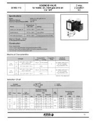
4<strong>Valve</strong> Monitoring SystemsRotary Position IndicatorDirect Mount for Rotary NAMUR ActuatorsAluminum BodySERIESNR1NR2Features• Set switches on-line without opening theelectrical enclosure• Eliminates bracketry for all NAMUR type actuators• Modular design for ease of field service• Enclosures are internally and externally coated forcorrosion resistance• Realview indicator with 100% color change, visiblefrom long distances• Environmentally sealed magnets^ % #ConstructionNR1NR2AreaClassificationsTypes 4, 4X,7 & 9Division 1Class I, Groups C&DClass II, Groups E,F,& GGroups A & B, Division 2Types 4, 4X,7 & 9Division 2Class I, Groups C&DClass II, Groups F,& GGroups A & B, Division 2Enclosure of BoxLow Copper AluminumBox Coating Black Polyester Lt. Grey Impreglon 309Indicator CoverPolycarbonateScrewsStainless SteelSealsNBR (Buna-N)Cam RingsPBT (Polybutylene)Magnet PackRyton (Polyphenylene Sulfide)MagnetsNickel Plated NeodymiumImpreglon 309 is a registered trademark of Impreglon Inc.Ryton is a registered trademark of Chevron-Phillips Chemical Co.Ambient Temperatures-4˚F to 140˚F (-20˚C to 60˚C) with Reed Switches-4˚F to 140˚F (-20˚C to 60˚C) with ASi, Device<strong>Net</strong>32˚F to 140˚F (0˚C to 60˚C) with IS FOUNDATION Filedbus, Profibus PA-40˚F to 140˚F (-40˚C to 60˚C) with Non-IS FOUNDATION FiledbusElectricalTungsten Switch PackSilicone FilledHermetically sealedHousing: ABSSPDT Form COperating Time: 3.0msInitial Contact Resistance: 0.5ohmsElectrical Rating: 3Amps/120VAC2Amps/24VDCMaximum power allowable is100watts or 100VAMinimum power required to ensureproper operation is 3watts or 3VARhodium Switch PackSilicone FilledHermetically sealedHousing: ABSSPDT Form COperating Time: 3.0msInitial Contact Resistance: 0.1ohmsElectrical Rating: 1Amp/24VACMaximum power allowable is25watts or 25VAMinimum current required to ensureproper operation is 10mA at 3VDCATEX category 1G, Intrinsic Safety OnlyII 1G EEx i a IIC T6KEMA 04ATEX 1025XAmbient Temperature: -18 to 170˚F (-28 to 77˚C)6 extra terminal points for accessoriesNOTE: <strong>ASCO</strong> requires 12VDC valves for Device<strong>Net</strong> <strong>Net</strong>workCards and 24VDC for AS-interface <strong>Net</strong>work Cards.Optional Features• Low power pilot valve mounted to enclosure• Attachable <strong>Net</strong>work Junction Box• AS-interface, Profibus-PA, Device<strong>Net</strong>, FOUNDATION Filedbuscommunication cards• Up to 3 conduit entries in 3/4” or 20mm• Alternate indicator color and path optionsSee list price schedule for available mounting bracketsand adapters.1
SERIESNR1NR2SpecificationsSeries Shaft Conduit 1 Indicator4<strong>Valve</strong> Monitoring SystemsChangeLetter Switches # Sw. <strong>Net</strong>work Communications ConnectorNR1Type 4, 4X, 7, 9, Div. 1NR2Type 4, 4X, Div. 2A=DirectMount2=(2) 3/4" NPT F4=(3) 3/4" NPT F7=(2) M20x1.5 F8=(3) M20x1.5 FB=Blue/WhiteD=Green/RedG=Green/WhiteR=Red/WhiteT=3-wayU=3-way DivertW=Red/GreenY=Yellow/BlackAG=Reed sw. SPDTRhodium (IS)R=Reed sw. SPDTRhodium 1AT=Reed sw. SPDTTungsten 3AW=<strong>Net</strong>work/BusComm. Card withinternal switches02NG=NoneAJ=ASI 2x1, v2.1, 31s STD ADDRAL=ASI 2x1, v2.1, 62s EXT ADDRAK=ASI 4x2, v2.1, 31s STD ADDRAM=ASI 4x2, v2.1, 62s EXT ADDRDC=DNET 2x1DE=DNET 2x1 DiagnosticsDD=DNET 6x2 (M1), 2 out, single actingDH=DNET 6x2 (M2), 1 out, double actingDF=DNET 6x2 DIAG (M1), 2 out, single actingDJ=DNET 6x2 DIAG (M2), 1 out, double actingA=ThreadedConduitB*=M-12 pinconnector forbus networkC*=Mini (7/8") pinconnector forbus network* Only available withswitch option (W)<strong>Net</strong>work/Bus Card.Not for Div. 1.NR1 A 2 Y A T 2 NG A1 Consult <strong>ASCO</strong> for optional pin connectors.Ordering Number Example: NR1A2YAT2NGADimensions Inches (mm)4.1[105]5.2[133]5.03 [ 128]6.73 [ 171]4.85 [ 123]4.9[124]1.82 [ 46]1.35 [ 34].20 [ 5]8.82 [ 224]1.18 [30]A Optionalthird Conduit1.57 [40]3.14 [80]2
4<strong>Valve</strong> Monitoring SystemsRotary Position IndicatorBracket Mounted for Rotary ActuatorsAluminum BodySERIESVR2VR3Features• Reduced enclosure size with lower profile for use in awide range of applications• Division 2 rated with hermetically sealed reed switches• Internal and external coating for corrosion resistance• Realview indicator with 100% change in color visiblefrom long distancesConstructionVR2VR3AreaType 4, 4xDiv. 2 - Class I, IIType 4, 4xClassificationsGroups A,B,C,D, F & GSwitch Type Reed / Inductive Proximity Switch Only Mechanical OnlyBodyCoatingIndicator CoverShaftBushingsHardwareAmbient TemperaturesReed Switches: -40˚F to 150˚F (-40˚C to 65˚C)Mechanical Switches: -40˚F to 170˚F (-40˚C to 77˚C)Potentiometer/Transmitter -4˚F to 140˚F (-20˚C to 60˚C)ASi, Device<strong>Net</strong> Bus Card: -4˚F to 140˚F (-20˚C to 60˚C)IS FOUNDATION Fieldbus, Profibus PA: 32˚F to 140˚F (0˚C to 60˚C)NON-IS FOUNDATION Fieldbus: -40˚F to 140˚F (-40˚C to 60˚C)(Contact <strong>ASCO</strong> for extended temperature range applications.)ElectricalLow Copper AluminumBlack Electrolytic PaintPolycarbonate316 Stainless SteelBronzeStainless SteelVR3 - Mechanical SwitchesGold ContactsMaximum 100mA@125/250VACMinimum 4mA@5VDCSilver ContactsMaximum 15A@125/250VACMinimum 125mA@125/250VACVR2 - Reed SwitchesTungsten: 120VAC@3A or 24VDC@2AMaximum power allowable is 100 Watts or 100VAMinimum power required to ensure proper operation is 3W or 3VARhodium: 24VDC@1AMaximum power allowable is 25 WattsMinimum current required to ensure proper operation is 10mA@3VDCRhodium (IS): 2mA to 1A@24VDC (suitable for IS applications)“IS”- Class I,II,III, Div. 1,Groups A,B,C,D,E,F, and GClass I, Zone 0, AEx ia IIC T6Class I, Zone 1, Ex ib IIC T6Class I, Zone 0, Ex ia IIC T6IS Inductive Proximity Switch5-25 VDC
SERIESVR2VR3SpecificationsSeries Shaft Conduit 1 IndicatorChangeLetter Switches # Sw. <strong>Net</strong>work Communications ConnectorE=Reed SPDT Rhodium 1AM=Reed SPDT Tungsten 3AN=No SwitchS=Reed SPDT Rhodium (IS)Q=NAMUR Proximity Sensor4<strong>Valve</strong> Monitoring Systems02NG=NoneA=ThreadedConduitVR2Div. 2 Type 4, 4XAluminumB=Non NAMUR316 S.S.C=NAMUR316 S.S.2=(2) 3/4" NPT F4=(3) 3/4" NPT F7=(2) M20x1.5 F8=(3) M20x1.5 FB=Blue/WhiteD=Green/RedG=Green/WhiteN=Flat Cover (None)R=Red/WhiteT=3-WayU=3-Way DivertW=Red/GreenY=Yellow/BlackAW=<strong>Net</strong>work Comm. Card 0NG=NoneAJ=ASI 2x1, v2.1, 31s STD ADDRAL=ASI 2x1, v2.1, 62s EXT ADDRAK=ASI 4x2, v2.1, 31s STD ADDRAM=ASI 4x2, v2.1, 62s EXT ADDRDC=DNET 2x1DE=DNET 2x1 DiagnosticsDD=DNET 6x2 (M1), 2 out, single actingDH=DNET 6x2 (M2), 1 out, double actingDF=DNET 6x2 DIAG (M1), 2 out, single actingDJ=DNET 6x2 DIAG (M2), 1 out, double actingFA=FF with 24VDC Non-ISFB=FF without 24VDC ISA=ThreadedConduitB=M-12 pinconnector forbus networkC=Mini (7/8”) pinconnector forbus networkVR3Type 4, 4XAluminumA =Mech SPDT Silver 15AD=Mech DPDT 10A*H=Mech SPDT Gold (IS)N=No Switch*Available with 2 switchesmaximum01234NG=NoneRW=RS (0-1000 Ohms) Potentiometer*TY=CS (4-20 MA) Transmitter** Available with (1) or (2) SPDTswitches or (1) DPDT switchA=ThreadedConduitVR2 B 2 Y A M 2 NG A1 Consult <strong>ASCO</strong> for optional pin connectors.Ordering Number Example: VR2B2YAM2NGADimensions Inches (mm)Box with 2 Switches5.714 (145)5.340 (136)3.745 (95)NAMUR5.548 (141)NON NAMUR4.786 (122)Dimensions for Both2.250 (57)1.380 (35)1.097 (28)CONDUITENTRIESNAMUR NON NAMURBOTH SIDES2.208 (56)1.30 (33) .538 (14)5.376 (137)5.413 (138)Box with 3 or 4 Switches, <strong>Net</strong>work Card or Transmitter2.250 (57)1.380 (35)5.714 (145)5.340 (136)3.745 (95)M6-1.312 MIN FULL THREAD4 PLACESNAMUR6.621 (168)NON NAMUR5.859 (149).690 (18)1.125 (29).3125-18 UNC-2B.312 MIN FULL THREAD4 PLACES1.097 (28)NAMUR1.30 (33)NON NAMUR.538 (14)2.208 (56)CONDUIT ENTRIESBOTH SIDES5.376 (137)5.413 (138)4
4<strong>Valve</strong> Monitoring SystemsRotary Position IndicatorBracket Mounted for Rotary ActuatorsResin BodySERIESVR4VR8Features• Resin body for corrosion resistance• Division 2 rated with hermetically sealed reed switches• Balanced bolt pattern for uniform sealing• Realview indicator with 100% change in color visiblefrom long distances) % #ConstructionVR4VR8Type 4, 4xAreaClassificationsType 4, 4xDiv. 2 - Class I, IIGroups A,B,C,D, F & GSwitch Type Mechanical Reed / Inductive Proximity SwitchBodyIndicator CoverShaftBushingsHardwareResilient PBTPolycarbonate316 Stainless SteelNylonStainless SteelAmbient TemperaturesReed Switches: -40˚F to 150˚F (-40˚C to 65˚C)Mechanical Switches: -40˚F to 170˚F (-40˚C to 77˚C)Potentiometer/Transmitter -4˚F to 140˚F (-20˚C to 60˚C)ASi, Device<strong>Net</strong> Bus Card: -4˚F to 140˚F (-20˚C to 60˚C)Profibus PA: 32˚F to 140˚F (0˚C to 60˚C)(Contact <strong>ASCO</strong> for extended temperature range applications.)ElectricalVR4 - Mechanical SwitchesGold ContactsMaximum 100mA@125/250VACMinimum 4mA@5VDCSilver ContactsMaximum 15A@125/250VACMinimum 125mA@125/250VACVR8 - Reed SwitchesTungsten: 120VAC@3A or 24VDC@2AMaximum power allowable is 100 Watts or 100VAMinimum power required to ensure proper operation is 3W or 3VARhodium: 24VDC@1AMaximum power allowable is 25 WattsMinimum current required to ensure proper operation is 10mA@3VDCRhodium (IS): 2mA to 1A@24VDC (suitable for IS applications)“IS”- Class I,II,III, Div. 1,Groups A,B,C,D,E,F, and GClass I, Zone 0, AEx ia IIC T6, Ambient = 170˚F (77˚C)Class I, Zone 1, AEx ib IIC T6IS Inductive Proximity Switch5-25 VDC
SERIESVR4VR84<strong>Valve</strong> Monitoring SystemsSpecificationsSeries Shaft Conduit 1 IndicatorVR4Type 4,4XResinChangeLetterSwitchesA=Mech SPDT Silver 15AD=Mech DPDT 10A*H=Mech SPDT Gold (IS)N=No Switch*Available with 2 switchesmaximum#Sw. <strong>Net</strong>work Communications Connector01234NG=NoneRW=RS (0-1000 Ohms) Potentiometer*TY=CS (4-20 MA) Transmitter** Available with (1) or (2) SPDTswitches or (1) DPDT switchA=ThreadedConduitVR8Div. 2 Type 4,4XResinB=Non NAMUR316 S.S.C=NAMUR316 S.S.2=(2) 3/4" NPT F7=(2) M20x1.5 FDimensions Inches (mm)B=Blue/WhiteD=Green/RedG=Green/WhiteN=Flat Cover (None)R=Red/WhiteT=3-WayU=3-Way DivertW=Red/GreenY=Yellow/Black1 Consult <strong>ASCO</strong> for optional pin connectors. ➁ VR4/VR8 available with a maximum of 12 terminal points.Ordering Number Example: VR8B2YAM2NGAAE=Reed SPDT Rhodium 1AM=Reed SPDT Tungsten 3AN=No SwitchS=Reed SPDT Rhodium (IS)Q=NAMUR Proximity Sensor02W=<strong>Net</strong>work Comm. Card 0NG=None* Available with (1) or (2) SPDTswitches or (1) DPDT switchNot available with reed switchesAJ=ASI 2x1, v2.1, 31s STD ADDRAL=ASI 2x1, v2.1, 62s EXT ADDRAK=ASI 4x2, v2.1, 31s STD ADDRAM=ASI 4x2, v2.1, 62s EXT ADDRDC=DNET 2x1DE=DNET 2x1 DiagnosticsDD=DNET 6x2 (M1), 2 out, single actingDH=DNET 6x2 (M2), 1 out, double actingDF=DNET 6x2 DIAG (M1), 2 out, single actingDJ=DNET 6x2 DIAG (M2), 1 out, double actingA=ThreadedConduitA=ThreadedConduitB=M12 pinconnector forbus networkC=Mini (7/8") pinconnector forbus networkVR8 B 2 Y A M 2 NG A6.940(176)NAMUR 7.506 (191)NON NAMUR 6.744 (171)1.176 (30)NAMUR 1.300 (33)NON NAMUR .538 (13)6.580(167)6.913(176)2.208(56)3/4 NPT OR M20 x 1.5BOTH SIDES1.125(28)2.250(57)2.250(57)2.250(57)2.250(57)1.962(50).3125-18 UNC-2B.312 MIN FULL THREAD4 PLACES1.125(28)2 CONDUIT 4 CONDUIT.3125-18 UNC-2B.312 MIN FULL THREAD4 PLACES6
4<strong>Valve</strong> Monitoring SystemsRotary Position IndicatorBracket Mounted for Rotary ActuatorsAluminum BodySERIESVR7Features• Heavy duty industrial design approved for Division 1Group B areas• Balanced bolt pattern for uniform sealing• Realview indicator with 100% change in color visiblefrom long distances) % #ConstructionAreaClassificationsBodyBody CoatingIndicator CoverShaftBushingsHardwareVR7Type 4, 4x, 7 and 9Div I, Class I,II,III, Groups B,C,D,E, F & GDiv. 2, Class I, Groups A,B,C & DClass I, Zone I, AEx d IIB T6Low Copper AluminumBlack Electrolytic PaintPolycarbonate316 Stainless SteelBronze (oil lite)Stainless SteelAmbient TemperaturesReed Switches: -40˚F to 150˚F (-40˚C to 65˚C)Mechanical Switches: -40˚F to 170˚F (-40˚C to 77˚C)Potentiometer/Transmitter -4˚F to 140˚F (-20˚C to 60˚C)ASi, Device<strong>Net</strong> Bus Card: -4˚F to 140˚F (-20˚C to 60˚C)IS FOUNDATION Fieldbus, Profibus PA: 32˚F to 140˚F (0˚C to 60˚C)NON-IS FOUNDATION Fieldbus: -40˚F to 140˚F (-40˚C to 60˚C)(Contact <strong>ASCO</strong> for extended temperature range applications.)ElectricalVR7 - Mechanical SwitchesGold ContactsMaximum 100mA@125/250VACMinimum 4mA@5VDCSilver ContactsMaximum 15A@125/250VACMinimum 125mA@125/250VACVR7 - Reed SwitchesTungsten: 120VAC@3A or 24VDC@2AMaximum power allowable is 100 Watts or 100VAMinimum power required to ensure proper operation is 3W or 3VARhodium: 24VDC@1AMaximum power allowable is 25 WattsMinimum current required to ensure proper operation is 10mA@3VDCRhodium (IS): 2mA to 1A@24VDC (suitable for IS applications)“IS”- Class I,II,III, Div. 1,Groups A,B,C,D,E,F, and GClass I, Zone 0, AEx ia IIC T6Class I, Zone 1, AEx ib IIC T6IS Inductive Proximity Switch5-25 VDC
4<strong>Valve</strong> Monitoring SystemsLinear Position IndicatorBracket Mounted for Linear ActuatorsAluminum BodySERIESHS1Features• Explosion proof, Div. 1 rated aluminum housing forhazardous locations• Simple to install and adjust• Understroke compensating switch triggers• 12 mounting positions (in 30˚ increments)• No seal fittings required with reed switches in Class I,Div. 1, Group A, B, C, & D areas• One construction accommodates strokes up to 2 inches% #ConstructionAreaBodyCoatingSwitch TriggersInner FrameZytel is a registered trademark of DuPont Co.Type 4, 4XLow Copper AluminumBlack Hard AnodizedABSZytel NylonAmbient TemperaturesReed Switches: -4˚F to 150˚F (-20˚C to 65˚C)ASi, Device<strong>Net</strong> Bus Card: -4˚F to 140˚F (-20˚C to 60˚C)IS Profibus PA: 32˚F to 140˚F (0˚C to 60˚C)Mechanical Switches: -40˚F to 170˚F (-40˚C to 77˚C)(Contact <strong>ASCO</strong> for extended temperature range applications.)ElectricalMechanical SwitchesGold ContactsMaximum 100mA@125/250VACMinimum 4mA@5VDCSilver ContactsMaximum 15A@125/250VACMinimum 125mA@125/250VACReed SwitchesTungsten: 120VAC@3A or 24VDC@2AMaximum power allowable is 100 Watts or 100VAMinimum power required to ensure proper operation is 3W or 3VARhodium: 24VDC@1AMaximum power allowable is 25 WattsMinimum current required to ensure proper operation is 10mA@3VDCRhodium (IS): 2mA to 1A@24VDC (suitable for IS applications)“IS”- Class I,II,III, Div. 1,Groups A,B,C,D,E,F, and GNOTE: <strong>ASCO</strong> requires 12VDC valves for Device<strong>Net</strong> <strong>Net</strong>work Cardsand 24VDC for AS-interface <strong>Net</strong>work Cards.ApprovalsFM approved for “Hazardous (Classified) locations”;Class 3600, 3610, 3611, & 3615.CSA Certified to Standard C22.2 No. 142-M “ProcessControl Equipment”; Hazardous Locations,Class 2258-02, 04, 82 & 84.Optional Features• Low power pilot valve mounted to enclosure• <strong>Net</strong>work Junction Box for hazardous locations• AS-interface, Profibus-PA, Device<strong>Net</strong> communicationcards with 2 sensors to indicate stem position• 2 or 3 conduit entries in 3/4" FNPTSee list price schedule for available mounting bracketsand adapters.9
SERIESHS14<strong>Valve</strong> Monitoring SystemsSpecificationsSeriesHazardous ClassifiedLocation Shaft Conduit IndicatorChangeLetter Switches # of Switches <strong>Net</strong>work/Bus Rev.HS1 SeriesType 4,4XIndoor/OutdoorExplosionproof:with SwitchesClass1/Div.1/A,B,C,D/T6Dust Ignition Proof:Class2,3/Div.1/E,F,G/T6Ambient Temp. = 77˚C/170˚FExplosionproof:with SwitchesClass1/Div.1/A,B,C,D/T6Dust Ignition Proof:Class2,3/Div.1/E,F,G/T6Ambient Temp. = 60˚C/140˚FExplosionproof:with Bus CardClass1/Div.1/A,B,C,D/T6Dust Ignition Proof:Class2,3/Div.1/E,F,G/T6Ambient Temp. = 60˚C/140˚FF=ITT(
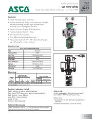
4<strong>Valve</strong> Monitoring SystemsLinear Position IndicatorBracket Mounted for Linear ActuatorsResin BodySERIESHS2HS3HS4Features• Process valve body is serviceable without removingindicator box• Built-in understroke compensation• Simple to install and adjust• Designed for caustic washdown• One construction accommodates valve strokes upto 2 inches• Indicator visible from 360˚ConstructionAreaClassificationsSwitch TypeBodyIndicator CoverSwitch TriggerInner Frame1 Mechanical SPDT gold plated switch is also available for intrinsically safe(IS) applications. * See Specifications Chart.Makrolon 2607 is a registered trademark of Bayer Inc.Ambient TemperaturesReed Switches: -4˚F to 150˚F (-20˚C to 65˚C)HS 2 HS 3 HS 4Type 4, 4XIndoorHazardousLocation*IP66OutdoorHazardousLocation*Mechanical / ReedASi, Device<strong>Net</strong> Bus Card: -4˚F to 140˚F (-20˚C to 60˚C)Profibus PA: 32˚F to 140˚F (0˚C to 60˚C)(Contact <strong>ASCO</strong> for extended temperature range applications.)Type 4, 4XIP66 Indoor/OutdoorNon-HazardousLocationValox 364 (Resilient PBT)Polycarbonate (Makrolon Grade 2607) UV StabilizedABSZytel NylonElectricalMechanical SwitchesGold ContactsMaximum 100mA@125/250VACMinimum 4mA@5VDCSilver ContactsMaximum 15A@125/250VACMinimum 125mA@125/250VACReed SwitchesTungsten: 120VAC@3A or 24VDC@2AMaximum power allowable is 100 Watts or 100VAMinimum power required to ensure proper operation is 3W or 3VARhodium: 24VDC@1AMaximum power allowable is 25 WattsMinimum current required to ensure proper operation is 10mA@3VDCRhodium (IS): 2mA to 1A@24VDC (suitable for IS applications)“IS”- Class I,II,III, Div. 1,Groups A,B,C,D,E,F, and GClass I, Zone 0, AEx ia IIC T6Class I, Zone 1, AEx ib IIC T6) % #ATEX category 1G, 2G Intrinsic Safety OnlyII 1G EEx i a IIC T6KEMA 04 ATEX 1025XAmbient Temperature: -18 to 170˚F (-28 to 77˚C)NOTE: <strong>ASCO</strong> requires 12VDC valves for Device<strong>Net</strong> <strong>Net</strong>workCards and 24VDC for AS-interface <strong>Net</strong>work Cards.ApprovalsFM approved for: “Hazardous (Classified) locations”;Class 3600, 3610 & 3611 (HS 2 & 3).Unclassified Locations (HS 4).CSA Certified to Standard C22.2 No. 142-M“Process Control Equipment”; Hazardous Locations,Class 2258-02, 04, 82 & 84 (HS 2 & 3), and GeneralRequirements, Class 2252-01(HS 4), File 013976-0-000.CE Certified.Optional Features• Attached low power pilot valve or with integrated valve.• AS-interface, Profibus-PA, Device<strong>Net</strong> communicationcards with 2 switches to indicate stem position.• Up to 2 conduit entries select from: 1/2" or 20mm.• Plug, cable gland, and network connectors.See list price schedule for available mounting bracketsand adapters.11
SERIESHS2HS3HS44<strong>Valve</strong> Monitoring SystemsSpecificationsSeries Hazardous Classified Location ShaftHS2 SeriesType 4,4XIndoorIntrinsically Safe:Class1,2,3/Div.1/A,B,C,D/T6Class1/Zone 0/AEx ia IIC/T6Class1/Zone 1/AEx ib IIC/T6Ambient Temp. = 77˚C/170˚FClass2/Div.1/A,B,C,D,E,F,GNon-Incendive: with ReedSwitchesClass1/Div.2/A,B,C,D/T6Class2/Div.2/F,G/T6 Except DustAmbient Temp. = 65˚C/150˚FSpecial Protection: Indoor OnlyNon-Incendive: with Bus CardClass1/Div.2/A,B,C,D/T6Class2/Div.2/F,G/T6Ambient Temp. = 60˚C/140˚FSpecial Protection: Indoor OnlyD=10-24Thread*Conduit /Connector 11=(2) 1/2 FNPT9=(1) 1/2 FNPT+ (1) M20 x 1.5IndicatorY=Yel/BlackChangeLetter Switches # of Switches <strong>Net</strong>work/Bus Connector1 M20 x 1.5 with PIN Connector required for Bus. * For correct operation, <strong>ASCO</strong> mouning bracket must be used. See <strong>ASCO</strong> <strong>VMS</strong> list price schedule for mounting kits.Ordering Example: HS2D1BYCT2NGACN=NoneH=Mech SPDTGold (IS)G=Reed SPDTRhodium (IS)T=Reed SPDTTungsten 3AR=Reed SPDTRhodium 1AW=<strong>Net</strong>work Card0=None0=NoneU=One Open UpperL=One Closed Lower2=Two0=NoneU=One Open UpperL=One Closed Lower2=Two2=TwoNG=NoneAJ=ASI 2x1, v2.1, Std AddressAL=ASI 2x1, v2.1, Ext AddressDC=DNET2x1DE=DNET 2x1 DiagnosticsA=ThreadedConduitA=ThreadedConduitB=M12 PinConnectorfor Bus<strong>Net</strong>worksC=Mini (7/8) PinConnectorfor Bus<strong>Net</strong>worksHS2 D 1 Y C T 2 NG ASeries Hazardous Classified Location ShaftHS3 SeriesIP-66OutdoorSeries Hazardous Classified Location ShaftHS4 SeriesType 4,4XIndoorIP-66 Indoor/OutdoorIntrinsically Safe:Class1,2,3/Div.1/A,B,C,D/T6Class1/Zone 0/AEx ia IIC/T6Class1/Zone 1/AEx ib IIC/T6Ambient Temp. = 77˚C/170˚FClass2/Div.1/A,B,C,D,E,F,GNon-HazardousD=10-24Thread*D=10-24Thread*Conduit /Connector 11=(2) 1/2 FNPT9=(1) 1/2 FNPT+ (1) M20 x 1.5Conduit /Connector 11=(2) 1/2 FNPT9=(1) 1/2 FNPT+ (1) M20 x 1.5IndicatorY=Yel/BlackIndicatorY=Yel/BlackChangeLetter Switches # of Switches <strong>Net</strong>work/Bus ConnectorCN=NoneH=Mech SPDTGold (IS)G=Reed SPDTRhodium (IS)T=Reed SPDTTungsten 3AR=Reed SPDTRhodium 1AW=<strong>Net</strong>work CardChangeLetter Switches # of Switches <strong>Net</strong>work/Bus ConnectorN=None 0=NoneA=ThreadedConduitB=M12 PinConnectorA=Mech SPDTCU=One Upper (open) NG=Nonefor BusSilver 15A<strong>Net</strong>worksL=One Lower (closed)H=Mech SPDTC=Mini (7/8) PinGold (IS) 2=TwoConnectorfor Bus<strong>Net</strong>worksHS4 D 1 Y C A 2 NG A0=None0=NoneU=One Open UpperL=One Closed Lower2=Two0=NoneU=One Open UpperL=One Closed Lower2=Two2=TwoNG=NoneAJ=ASI 2x1, v2.1, Std AddressAL=ASI 2x1, v2.1, Ext AddressDC=DNET2x1DE=DNET 2x1 DiagnosticsA=ThreadedConduitA=ThreadedConduitB=M12 PinConnectorfor Bus<strong>Net</strong>worksC=Mini (7/8) PinConnectorfor Bus<strong>Net</strong>worksHS3 D 1 Y C T 2 NG ADimensions: Inches (mm)3.67 [93]TOP VIEW1.89 [48]3.73 [ 95]4.88 [124]1/2 NPT ORM20 x 1.52 PLACESSIDE VIEW123.78 [96]1.08 [27]1.08 [27]
4<strong>Valve</strong> Monitoring SystemsLinear Position IndicatorBracket Mounted with Integrated <strong>Valve</strong> for Linear ActuatorsResin/Aluminum BodySERIESHSINTEGRATEDIndicator with Integrated <strong>Valve</strong> Features• Simpler to order• Available in 0.3 Cv only• Solenoid valve is environmentally protectedinside the housing• Reliable poppet construction• Built-in relief valve prevents pressurizing ofinternal indicator housing• External manual override% #PENDINGPENDINGSolenoid <strong>Valve</strong> Specifications• 1/4" NPT threaded ports• Cv flow factor of 0.3• Medium - AIR or INERT GASES only• Pressure min. & max. - 30 to 120 psi• Recommended filtration - 50 microns (50um)• Coil wattage of 0.5 Watt in 24VDC or 1.0 Watt in12VDC, 120/60 or 240/60Optional Features• AS-interface, Device<strong>Net</strong> communicationcards with 2 switches to indicate stem position.• 2 conduit entries select from: 1/2" or 20mm.See list price schedule for available mounting bracketsand adapters.Integrated <strong>Valve</strong> ConstructionBodyHardwarePopetSealing MaterialAnodized AluminumStainless SteelStainless SteelNBRIndicator ConstructionHS 2 HS 4AreaClassificationsSwitch TypeBodyIndicator CoverSwitch TriggerInner FrameType 4, 4XIndoorHazardous Location*Mechanical / ReedType 4, 4XIP66 Indoor/OutdoorNon-Hazardous LocationValox 364 (Resilient PBT)Polycarbonate (Makrolon Grade 2607) UV StabilizedABSZytel Nylon13
SERIESHSINTEGRATED4<strong>Valve</strong> Monitoring SystemsSpecificationsSeriesHS2 SeriesType 4,4XIndoor OnlyHS4 SeriesType 4,4XIndoor IP-66Indoor/OutdoorHazardousClassifiedLocationNon-IncendiveClass1/Div. 2/A,B,C,D/T4Class1/Div. 2/F,G/T4Ambient Temp. = 60˚C/140˚FSpecial Protection:Indoor OnlyIntrinsically Safe:Class1,2,3/Div.1/A,B,C,D/T6Class1/Zone 0/AEx ia IIC/T6Class1/Zone 1/AEx ib IIC/T6Ambient Temp. = 60˚C/140˚FClass2/Div.1/A,B,C,D,E,F,GNon-HazardousOrdering Example with valve: HS2DCYCW2DEC15FDescription: (HS2 Series with #10-24 Shaft thread, (1) M20x1.5 threaded conduit, yellow/black indicator, (2) hall effect sensors, D<strong>Net</strong> Bus Card with diagnostics,Mini (7/8") pin connector, 3/2 NC 1/4 NPT valve, screw-in manual operator, 12VDC)* For correct operation, <strong>ASCO</strong> mouning bracket must be used. See <strong>ASCO</strong> <strong>VMS</strong> list price schedule for mounting kits.Integrated Solenoid <strong>Valve</strong> OrderingDimensions: Inches (mm)ShaftD=#10-24Thread*D=#10-24Thread*D=#10-24Thread*Conduit /Connector 1Construction Port #1 Port #2 Port #33/2 NC Pressure Cylinder ExhaustIndicatorChangeLetter Switches # of Switches <strong>Net</strong>work/Bus ConnectorA=(1) 1/2 FNPTC=(1) M20 x 1.5 Y=Yel/Black C N=No SwitchT=Reed SPDT Tungsten 3AR=Reed SPDT Rhodium 1A0=NoneW=<strong>Net</strong>work CardA=(1) 1/2 FNPTC=(1) M20 x 1.5 Y=Yel/Black C G=Reed SPDT Rhodium (IS)H=Mech SPDT Gold (IS)U=One Open/UpperL=One Closed/Lower2=TwoU=One Open UpperL=One Closed Lower2=Two2=TwoA=(1) 1/2 FNPTC=(1) M20 x 1.5 Y=Yel/Black C N=No SwitchA=Mech SPDT Silver 15AH=Mech SPDT Gold (IS)T=Reed SPDT Tungsten 3AR=Reed SPDT Rhodium 1A0=NoneW=<strong>Net</strong>work CardU=One Open UpperL=One Closed Lower2=TwoU=One Open/UpperL=One Closed/Lower2=TwoU=One Open/UpperL=One Closed/Lower2=Two2=TwoNG=NoneAJ=ASI 2x1, v2.1,Std AddressAL=ASI 2x1, v2.1,Ext AddressDC=DNET2x1DE=DNET 2x2DiagnosticsNG=NoneNG=NoneAJ=ASI 2x1, v2.1,Std AddressAL=ASI 2x1, v2.1,Ext AddressDC=DNET2x1DE=DNET 2x2DiagnosticsA=Threaded ConduitA=Threaded ConduitB=M12 pinconnector forBusC=Mini (7/8") pinconnector for busA=Threaded ConduitA=Threaded ConduitA=Threaded ConduitB=M12 pinconnector forBusC=Mini (7/8") pinconnector for busHS2 D C Y C W 2 DE C<strong>Valve</strong> Manual Operator VoltagesCode Operation Pipe Code Type To Operate Code VoltageA 120/601 3/2 NC 1/4 NPT 5 Screw In Screw Driver1 5 FB 240/60DEF24/DCIS12/DCØ3.57 [93]1.89 [48]3.73 [95]4.88 [124].409 [10.4].39 [10].610 [15.5]5.007 [127.18]141/2 NPTM20 x 1.5THREAD3.047 [77.4].610 [15.5].276 [7].409 [10.4]
4<strong>Valve</strong> Monitoring SystemsDevice<strong>Net</strong> <strong>Net</strong>work CardFeatures• Advance technology allows solenoid output to operatethroughout Device<strong>Net</strong> voltage• Onboard diagnostics provides easy calibration• ODVA conformance tested to Composite 18• Fully encapsulated electronics module• Bus powered inputs and outputs• Two built-in sensors for OPEN/CLOSE detection• Short/Open Circuit protection• EMC certified to directive 89/336/EEC//93/68/EEC(Per Stds. EN61000-6-4, EN61000-6-2)Visual DiagnosticsOPEN POSITIONCLOSED POSITIONLED FOR BUS LINE STATUS• No LED lit: No power• Flashing Green: Online but no established Device<strong>Net</strong> connections• Solid Green: Online with established Device<strong>Net</strong> connections• Flashing Red: Timed out Device<strong>Net</strong> I/O connection(s)• Solid Red: Communication fault: Duplicate address or incorrect baud rate<strong>ASCO</strong> <strong>Valve</strong> Monitoring Systems is an integrated network module and limit switch package that connects automatedvalves and external devices directly to the control system reducing the I/O interfaces and wiring associated with a typicalhardwired solution. The Device<strong>Net</strong> <strong>Net</strong>work Card is fully encapsulated for superior environmental protection, and LEDsprovide visual status of network connection and valve position. Optional diagnostics provide built-in maintenance toolssuch as cycle count, travel times, self-calibration, and valve information. Our network cards operate with our NR and VRseries rotary or HS series linear indicators. Enclosures types range from Nema 4, 4X to Class 1, Division 1, Groups B,C & D. Accessories such as a <strong>Net</strong>work Junction Box are available.Note: <strong>ASCO</strong> recommends using 12 VDC pilot valves with Device<strong>Net</strong> cards.Device<strong>Net</strong> Technical SpecificationsMaximum DistancePhysical MediaAvailable I/O<strong>Net</strong>work TopologySupported Baud RateDiagnosticsBus Voltage500 Meters/1640 Feet @ 125Kbps, 250 Meters/820 Feet @ 250kbps, 100 Meters/328 Feet @ 500KbpsFour wire system (two for communication and two for power)2 inputs, 1 output6 inputs, 2 output (includes 4 general purpose inputs)Trunk line/dropline with branching125 Kbps, 250 Kbps, 500 KbpsYes11-25 VDCOrdering Number Example: VR7C2YAW0_ _ADC = D<strong>Net</strong> 2x1DE = D<strong>Net</strong> 2x1 with diagnosticsDD = D<strong>Net</strong> 6x2 (m1), 2 outputs, single actingDH = D<strong>Net</strong> 6x2 (m2), 1 output, double actingDF = D<strong>Net</strong> 6x2 with diagnostics (m1), 2 outputs, single actingDJ = D<strong>Net</strong> 6x2 with diagnostics (m2), 1 output, double acting15
Diagnostics4<strong>Valve</strong> Monitoring SystemsStandard DiagnosticsInput Status – state of input whether valve is CLOSED or OPENSolenoid Voltage – indicates the voltage applied to solenoidOutput Status – indicates whether the solenoid output is in open or short circuit conditionBus Voltage – indicates the Device<strong>Net</strong> voltage at that node<strong>Valve</strong> Tag # – 16 character text for user input of node id<strong>Valve</strong> Manufacturer – 16 character text for user input of valve manufacturer of particular nodeActuator Manufacturer – 16 character text for user input of actuator manufacturer of particular node<strong>Valve</strong> Serial # – 16 character text for user input of valve serial # of particular nodeActuator Serial # – 16 character text for user input of actuator serial # of particular node<strong>Valve</strong> ID # – 16 character text for user input of valve ID (part number or type) of particular nodeActuator ID# – 16 character text for user input of actuator ID (part number or type) of particular nodeExtended DiagnosticsCycle Count Pilot <strong>Valve</strong> – actual number of cycle, OPEN-to-CLOSE and CLOSE-to-OPEN for the pilot valveCycle Count Limit Pilot <strong>Valve</strong> – operational cycle limit of the pilot valve. Once limit is exceeded a fault will be sent to PLC/DCS indicating limit exceededCycle Count Actuator – actual number of cycle, OPEN-to-CLOSE and CLOSE-to-OPEN for the actuatorCycle Count Limit Actuator - operational cycle limit of the actuator. Once limit is exceeded a fault will be sent to PLC/DCS indicating limit exceededCycle Count Main <strong>Valve</strong> (Process <strong>Valve</strong>) – actual number of cycle, OPEN-to-CLOSE and CLOSE-to-OPEN for the pilot valveCycle Count Limit Main <strong>Valve</strong> (Process <strong>Valve</strong>) – operational cycle limit of the main valve. Once limit is exceeded a fault will be sent to PLC/DCS indicatinglimit exceededNote: the Travel & Break Time below are accurate to 10msTravel Time OPEN-to-CLOSE – the last time between the change-in-state command-CLOSE and the indication the valve is in the CLOSE position.This is the recorded value of the last time the valve was used.Setpoint Travel Time OPEN-to-CLOSE – calibration value of the time between the change-in-state command-CLOSE and the indication the valve isin the CLOSE position. This value is automatically recorded & saved during Calibration command.Tolerance Travel Time OPEN-to-CLOSE – maximum allowable difference between Travel Time OPEN-to-CLOSE & Setpoint Travel Time OPEN-to-CLOSE.If Travel Time exceeds Setpoint + Tolerance, then a fault will be sent to PLC/DCS indicating limit exceeded.Travel Time CLOSE-to-OPEN – the last time between the change-in-state command-OPEN and the indication the valve is in the OPEN position. Thisis the recorded value of the last time the valve was used.Setpoint Travel Time CLOSE-to-OPEN – calibration value of the time between the change-in-state command-OPEN and the indication the valve is inthe OPEN position. This value is automatically recorded & saved during Calibration command.Tolerance Travel Time CLOSE-to-OPEN – maximum allowable difference between Travel Time CLOSE-to-OPEN & Setpoint Travel Time CLOSE-to-OPEN.If Travel Time exceeds Setpoint + Tolerance, then a fault will be sent to PLC/DCS indicating limit exceeded.Break Time OPEN-to-CLOSE – the last time between the change-in-state command-CLOSE and the indication the valve leaves the OPEN state. Thisis the recorded value of the last time the valve was used.Setpoint Break Time OPEN-to-CLOSE – calibration value of the time between the change-in-state command-CLOSE and the indication the valveleaves the OPEN state. This value is automatically recorded & saved during Calibration command.Tolerance Break Time OPEN-to-CLOSE – maximum allowable difference between Break Time OPEN-to-CLOSE & Setpoint Break Time OPEN-to-CLOSE.If the Break Time exceeds Setpoint + Tolerance, then a fault will be sent to PLC/DCS indicating limit exceeded.Break Time CLOSE-to-OPEN – the last time between the change-in-state command-OPEN and the indication the valve leaves the CLOSE state. Thisis the recorded value of the last time the valve was used.Setpoint Break Time CLOSE-to-OPEN – calibration value of the time between the change-in-state command-OPEN and the indication the valve leavesthe CLOSE state. This value is automatically recorded & saved during Calibration command.Tolerance Break Time CLOSE-to-OPEN – maximum allowable difference between Break Time CLOSE-to-OPEN & Setpoint Break Time CLOSE-to-OPEN.If the Break Time exceeds Setpoint + Tolerance, then a fault will be sent to PLC/DCS indicating limit exceeded.Configurable Behavior – in the event that the PLC/DCS stops communicating the device as the ability to automatically switch to a “Fail Safe” position.Input Identifier – for versions with 4 extra inputs the device has 4 general purpose identifiers (16 characters max for each) for user input of devicesconnected to those inputs.16
4<strong>Valve</strong> Monitoring SystemsAS-interface <strong>Net</strong>work CardFeatures• AS-interface certified• Fully encapsulated electronic module®• Bus powered inputs & outputs• Two built-in sensors for OPEN/CLOSE detection• Short circuit protection for inputs and outputs• LEDs for visual indication:- OPEN/CLOSE- Solenoid output- Bus communication- Faults• EMC certified (per stds. EN61000-6-2, EN61000-6-4)Visual DiagnosticsOPEN POSITION: Yellow LEDBUS STATUS: Green LEDCLOSED POSITION: Yellow LEDSOLENOID: Red LEDBUS FAULT: Red LED<strong>ASCO</strong> <strong>Valve</strong> Monitoring Systems is designed for monitoring and controlling the position of valve actuators via AS-interfaceV2.1. The AS-interface <strong>Net</strong>work Card is fully encapsulated for superior environmental protection and features plug-interminal blocks for easy maintenance, built-in sensors for OPEN/CLOSE detection, and LEDs to provide visual status ofnetwork connection and actuator position. Our network cards operate with our NR and VR series rotary or HS series linearindicators. Enclosure types range from NEMA 4, 4X to Class 1, Division 1, Groups B, C & D. Accessories such as a <strong>Net</strong>workJunction Box are available.Note: <strong>ASCO</strong> recommends using 24 VDC pilot valves with AS-interface cards.Technical SpecificationsMaximum DistancePhysical MediaMaximum NodesAvailable I/O<strong>Net</strong>work TopologyBaud Rate100m (330 ft)Two-wire cable622 inputs, 1 output4 inputs, 2 output (includes 2 general purpose input)Bus, Tree, Star167 KbpsOrdering Number Example: VR7C2YAW0_ _AAJ = ASI 2x1, Version 2.1, standard addressing, 31 slavesAL = ASI 2x1, Version 2.1, extended addressing, 62 slavesAK = ASI 4x2, Version 2.1, standard addressing, 31 slavesAM = ASI 4x2, Version 2.1, extended addressing, 62 slaves17
FOUNDATION Fieldbus4<strong>Valve</strong> Monitoring SystemsThe <strong>ASCO</strong> FOUNDATION Fieldbus Type 4449 (FF4449)The <strong>ASCO</strong> FF4449 is EMC (electro-magnetic Compliance) approved to ensureimmunity against electrical interference from equipment such as hand heldradios and has one of the industries lowest power consumption at 12.5mA total.Unlike competitors, the <strong>ASCO</strong> FF4449 has Link Active Scheduler (LAS)capability and can be configured as a backup Link Master. In the event thatcommunication with the DCS is lost, the FF4449 becomes Link Master ofthe bus segment and keeps the process running preventing down time. Itcan also be configured as a Basic device. In this configuration, it can bepre-programmed to move to a Fail-safe position (OPEN or CLOSE) or holdlast valid command when communication with the DCS is lost.FF4449 can be configured to operate with both spring return (single acting)and double acting actuators.Visual DiagnosticsCLOSED DETECTION: Yellow LEDEXTERNAL 24VDC DETECTION: Green LEDOPEN DETECTION: Yellow LEDThe outputs for the FF4449 can be powered with either an external 24VDC or from the bus.• For bus powered applications, since available power for operating pilotvalves is limited, piezo based pilot valves must be useddue to its inherent low power consumption (typically 6.6VDC @ 1.4mA). The total power consumption for the FF4449 remains at12.5mA. In this application an external 24Vdc supply is NOT NEEDED. Power for the outputs will be taken from the fieldbus line.With the piezo pilot valves, the operating temperature range is from 0ºC to 60ºC (32ºF to 140ºF). This configuration is requiredfor Intrinsically Safe application.• For non-intrinsically safe applications an external 24VDC can be used to supply extra power to the outputs. This will allow customers to use traditional solenoid based pilot valves of up to 1.4watts. In this configuration, the operating temperature range isfrom -40ºC to 60ºC (-40ºF to 140ºF).Approvals• FOUNDATION Fieldbus Inter-operability test (ITK 4.61)• EMC Directive (89/336/EEC//93/68/EEC) per EN 61326• CSA approved• FM approved• Delta V – certified as Link Master<strong>ASCO</strong> <strong>Valve</strong> Monitoring Systems power the PlantWeb digital architecture via FOUNDATION Fieldbus bymonitoring the diagnostic feedback received from the actuator and process valve to which it is attached. Inaddition to the various diagnostics available in the <strong>ASCO</strong> FF, the device also has integrated PlantWeb alerts.With PlantWeb alerts, users can set limits for the device performance. Once the limits in desired performancehave been exceeded the device can communicate the information to the user through Plantweb. ThePlantweb alerts in also user configurable to either failure, advisory, or maintenance.18
4<strong>Valve</strong> Monitoring SystemsFOUNDATION FieldbusDiagnosticsShort Circuit – detection that outputs are shorted. Separate detection for output # 1 & 2External Voltage – detection that an external 24Vdc supply is connected. This feature is disabled if FF4449 is configured forpiezo valves (Bus powered application)Time in Position – the time the Process <strong>Valve</strong>/Actuator has been in its current position. This information is valuable in determining if the valve/actuator needs to be cycled to ensure it is not frozen in its current position.Travel Deviation / Lost Position – an alert generated if the valve/actuator moves to a position that is not desired. For example– the FF4449 energizes an output to OPEN a spring return actuator. The position feedback indicates the device has reachedOPEN position. Afterwards, air pressure is lost and the actuator moves back to the CLOSED position (spring-return). Theposition feedback sensor will indicate the actuator in the CLOSED position although a command to CLOSE the actuator was neverissued. In this situation a Travel Deviation alert will be generated indicating the actuator was in a desired position, but movedto undesired positionTravel Counters – the FF4449 is available with counters that record the number of travels the device has gone through. Twotravel counts equals one cycle (travel OPEN + travel CLOSE = 1 cycle). Settable limit indicators are also available. Once thetravel count has exceeded the value set in the limit and alert will be generated. There are 3 Travel Counters and limits for thefollowing: • Pilot <strong>Valve</strong> • Actuator • Process <strong>Valve</strong>OPEN Times:Calibrated Travel Time Open – calibration value of the time between the change-in-state command-OPEN and the indicationthe valve is in the OPEN position. This value is automatically recorded & saved during Calibration commandLast Travel Time Open – Last time between Open command and the indication the valve reaches the Open stateAverage Travel Time Open – Average of up to last 30 values. Time between Open command and the indication the valvereaches the Open stateCalibrated Break Time Open – calibration value of the time between the change-in-state command-OPEN and the indicationthe valve leaves the CLOSE state. This value is automatically recorded & saved during Calibration commandLast Break Time Open – Last time between Open command and the indication the valve leaves the Closed stateAverage Break Time Open – Average of up to last 30 values. Time between Open command and the indication the valve leavesthe Closed stateCLOSED Times:Calibrated Travel Time Close – calibration value of the time between the change-in-state command-CLOSE and the indicationthe valve is in the CLOSE position. This value is automatically recorded & saved during Calibration commandLast Travel Time Close – Last time between CLOSE command and the indication the valve reaches the CLOSE stateAverage Travel Time Close – Average of up to last 30 values. Time between CLOSE command and the indication the valveleaves the Open stateCalibrated Break Time Close – calibration value of the time between the change-in-state command-CLOSE and the indicationthe valve leaves the OPEN state. This value is automatically recorded & saved during Calibration commandLast Break Time Close – Last time between CLOSE command and the indication the valve leaves the Open stateAverage Break Time Close – Average of up to last 30 values. Time between CLOSE command and the indication the valvereaches the CLOSE stateAverage Time Values (Travel & Break times for Open & CLOSE) – process valve/actuators typically wear out at a constant steadily pace.A good indication of wear will be the average travel times since the change is slow, but constant.Last Time Values (Travel & Break times for Open & CLOSE) – these values are important in determining abnormal events thatrecently occurred. For example, a temporary drop in pressure or a sticky process valve (valve that has been left in the same positionfor a long time without cycling) will affect the performance of the last operation of the valve, but does not necessarily mean themechanical device is worn out.19
Reed Switch Assembly4<strong>Valve</strong> Monitoring SystemsFeatures• Each switch cup contains either two Tungsten,two Rhodium, or two Rhodium (IS) Reed switches• Fully encapsulated hermetically sealed Reed SwitchesReed Switch Ambient Temperature-40˚F to 150˚F (-40˚C to 65˚C)ConstructionCupEncapselantContactsABSSiliconeStainless SteelElectricalReed SwitchesTungsten: 120VAC@3A or 24VDC@2AMaximum power allowable is 100 Watts or 100VAMinimum power required to ensure proper operation is 3W or 3VARhodium: 24VDC@1AMaximum power allowable is 25 WattsMinimum current required to ensure proper operation is 10mA@3VDCRhodium (IS): 2mA to 1A@24VDC (suitable for IS applications)“IS”- Class I,II,III, Div. 1,Groups A,B,C,D,E,F, and GClass I, Zone 1, AEx ib IIC T6Class I, Zone 1, Ex ib IIC T6Class I, Zone 0, Ex ia IIC T6Ordering Number Example: VR2C2Y_2NGAM = REED SPDT Tungsten 3AE = REED SPDT Rhodium 1AS = REED SPDT Rhodium (IS)20
4<strong>Valve</strong> Monitoring SystemsPotentiometer or TransmitterVR Series OptionFeaturesPotentiometer• 0 to 1000 ohm resistive outputs to control system,proportional to the process valve positionTransmitter• 4-20mA signal outputs to control system, proportionalto the process valve position• Easy calibration of transmitter with on-board LED andcalibration button• Calibration settings stored in non-volatile memory• Gear drive mechanism located above switches for easyaccess and adjustments (for 0-10K ohms potentiometer)• All transmitters are rated for use in intrinsically safe ornon-incendive areas• Fully encapsulated transmitter circuit board forenvironmental protection• Clockwise or counter-clockwise operation with reversiblesignal outputs# %Potentiometer 1K ohmsTransmitterElectricalPotentiometer SpecificationsShaft Rotation Range 0-95˚Resistance0-1000 ohmsFull Scale Tolerance± 100 ohmsLinearity ± 2.0%Rotation300˚Terminals12 pts for pot/switches/accessoriesTransmitter SpecificationsShaft Rotation Range0-95˚ (45˚ minimum)Input Voltage Range8-38 VDCPotentiometer Resistance0-10,000 ohmsOutput Signal Range4-20mA DCLoad Impedance Range0-800 ohms at 24 VDCOutput Impedance25 M ohms (typical)Offset Error at 4mA± 20 µA (max)Offset Drift± 500 µA / ˚C (max)Span Error at 20mA± 40 µA (max)Span Drift± 1000 µA / ˚C (max)Linearity ± 2.0%Hysteresis1.0% of full scaleRepeatability± 0.3% of full scaleInput Voltage Effects2 µA/V (typical)CalibrationAuto-setting via pushbuttonIndicationRed LED (variable brightness with position)Terminals2pts for 4-20mA + 8pts for switches/accessoriesHow to SpecifyPotentiometer Option - RW(0-1000ohms resistive output)Transmitter Option - TY(4-20mA signal output)Ordering ExampleVR8B2YAM2RWAVR8B2YAM2TYAVR8B2YANOTYA (without switches)Mechanical Switch and <strong>Net</strong>work Card available together.21
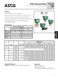
3/2SERIES83553-Way Normally Closed Pilot <strong>Valve</strong>sfor assembly to <strong>VMS</strong> boxes4<strong>Valve</strong> Monitoring SystemsFeatures• Explosionproof, Type 4 & 4X and Intrinsically Safe solenoids• Poppet design provides durability and reliability in awide range of ambient temperatures• Nickel plated brass, or 316 stainless steel bodiesdesigned for harsh process conditions• Built-in speed controls and rebreather connection• High efficiency, low wattage coils (2 watt ACand .5 watt DC)• 1/4" NPT inline connection• Cv factor of 0.9• Easy positioning with adjustable stainless steelconduit coupler% #312ConstructionPartBodySolenoid EnclosureSeals and DiscMaterialNickel Plated Brass, 316 Stainless SteelRyton (Polyphenylene Sulfide)Buna “N”Electrical120/60 AC12V 11 12V compatible with Device<strong>Net</strong>, 24V compatible with AS-iSee next page for IS Entity Parameters.DC24V 1IS 24VDCNominal Watt Rating 2.0w .5w .5w .5wOperating Current 25.3mA 30mA 15mA 29mAAmbient Temperatures-20˚C to 70˚C (-4˚F to 158˚F)Solenoid EnclosuresEnclosure Option CodeEE Div. 1 with 3/4" MNPT connectorB0 Type 4 & 4x with 20mm x 1.5 connectorAS Intrinsically Safe with 3/4" MNPT connectorBS Intrinsically Safe with 20mm x 1.5 connectorVoltage CodesAG - 120/60 AJ - 230/60D2 - 24/DC D1 - 12/DCFor applications requiring a Cv greater then 0.9 consult <strong>ASCO</strong>.Ratings and ApprovalsB0 - Type 4 & 4X - (Indoor and outdoor locations)EE - Class I, Div. 1, Groups A,B,C, & D Class II, Div. 1,Groups E,F, & G Non-incendive Class I, Div. 2, GroupsA,B,C, & D Class II, Div. 2, Groups F & G Hazardouslocations Class I, Zone 1 AEx d m IIC T6 @ 70˚CAS, BS - Intrinsically Safe Class I, II, III, Div. 1,Groups A-G, Class I, Zone 0, AEx ia IIC T6 @ 70˚CATEX category 1G, Operator OnlyII 1G EEx i a IIC T6KEMA 03ATEX 1173XAmbient Temperature: -40 to 140˚F (-40 to 60˚C)Optional FeaturesSpecify suffix codes for manual operatorsMI - Momentary (push in & hold)MS - Sustained (push in & turn)22
4<strong>Valve</strong> Monitoring Systems3/2SERIES8355Entity Parameters for Intrinsically Safe options AS & BSGroups A-G V max I max P max Capacitance InductanceParameters 30 VDC 100 mA 0.75 w 0 nf 0 mHSpecificationsOperating PressureDifferential (psi)Pipe OrificeMax.size Dia. CvMax. AC/DCFluid Nickel Plated 316 Stainless Const.(ins.) (ins.) Flow Min.Air-Inert GasMedia Temp.˚F BrassSteelRef.1/4 1/4 0.9 35 125 AIR 180 8355A002 8355A082 1Enclosure Voltage OptionsOrdering Example: 8355A082 EE AG MIDimensions Inches (mm)Const. Ref. 1TOPENDSCREW.68[17].99 [25]2.25 [57].50 [13]1.43 [36]NAMEPLATE3.69 [94].31 [8]SPEED CONTROLSIDEBOTTOM1.25 [32]2.97 [76]1.43 [36].38 [10]1.63 [41]23
4/2SERIES84554-Way Pilot <strong>Valve</strong>sfor assembly to <strong>VMS</strong> boxes4<strong>Valve</strong> Monitoring SystemsFeatures• Explosionproof, Type 4 & 4X and Intrinsically Safe solenoids• Poppet design provides durability and reliability in awide range of ambient temperatures% #• Nickel plated brass, or 316 stainless steel bodiesdesigned for harsh process conditions• Built-in speed controls• High efficiency, low wattage coils (2 watt ACand .5 watt DC)• 1/4" NPT inline connection• Cv factor of 0.9• Easy positioning with adjustable stainless steelconduit coupler4312ConstructionPartBodySolenoid EnclosureSeals and DiscMaterialNickel plated brass, 316 Stainless SteelRyton (Polyphenylene Sulfide)Buna "N"Electrical120/60 AC12V 1DC24V 1IS 24VDCNominal Watt Rating 2.0w .5w .5w .5wOperating Current 25.3mA 30mA 15mA 29mA1 12V compatible with Device<strong>Net</strong>, 24V compatible with AS-iSee next page for IS Entity Parameters.24Ambient Temperatures-20˚C to 70˚C (-4˚F to 158˚F)Solenoid EnclosuresEnclosure Option CodeEE Div. 1 with 3/4" MNPT connectorB0 Type 4 & 4x with 20mm x 1.5 connectorAS Intrinsically Safe with 3/4" MNPT connectorBS Intrinsically Safe with 20mm x 1.5 connectorVoltage CodesAG - 120/60 AJ - 230/60D2 - 24/DC D1 - 12/DCFor applications requiring a CV greater then 0.9 consult <strong>ASCO</strong>.Ratings and ApprovalsB0 - Type 4 & 4X - (Indoor and outdoor locations)EE - Class I, Div. 1, Groups A,B,C, & DClass II, Div. 1, Groups E,F, & GNon-incendive Class I, Div. 2, Groups A,B,C, & DClass II, Div. 2, Groups F & GHazardous locations Class I, Zone 1AEx d m IIC T6 @ 70˚CAS, BS - Intrinsically Safe Class I, II, III, Div. 1,Groups A-G, Class I, Zone 0, AEx ia IIC T6 @ 70˚CATEX category 1G, Operator OnlyII 1G EEx i a IIC T6KEMA 03ATEX 1173XAmbient Temperature: -40 to 140˚F (-40 to 60˚C)Optional FeaturesSpecify suffix codes for manual operatorsMI - Momentary (push in & hold)MS - Sustained (push in & turn)
4<strong>Valve</strong> Monitoring Systems4/2SERIES8455Entity Parameters for Intrinsically Safe options AS & BSGroups A-G V max I max P max Capacitance InductanceParameters 30 VDC 100 mA 0.75 w 0 nF 0 mHSpecificationsOperating PressureDifferential (psi)Pipe OrificeMax.size Dia. CvMax. AC/DCFluid Nickel Plated 316 Stainless Const.(ins.) (ins.) Flow Min.Air-Inert GasMedia Temp.˚F BrassSteelRef.1/4 1/4 0.9 35 125 AIR 180 8455A002 8455A082 1Enclosure Voltage OptionsOrdering Example: 8455A082 EE D2 MIDimensions Inches (mm)Const. Ref. 1TOPSCREWEND1.0 [25]1.16 [30].99 [25]2.25 [57].40 [10]1.45 [37]3.69 [94]NAMEPLATE3.47 [88].40 [10]BOTTOMSIDE1.28[32]1.93 [49].39 [10]1.30 [33]SPEED CONTROL25
Slip-Lok Connectorfor attaching conduit and instruments4<strong>Valve</strong> Monitoring SystemsFeatures• Patented two piece design for easy installation ofequipment in hazardous locations• Allows for optimal positioning of components, and locksthem into position• Reduces time required for connecting and disconnectingconduit from instruments• Male NPT threaded connections - No specialadapters needed• All 303 stainless steel construction to resist corrosion^ %ConstructionBodyPartMaterial303 Stainless SteelO-RingBuna "N"Ambient Temperatures-20˚F to 180˚F (-29˚C to 82˚C)Ratings and ApprovalsUL approvedFor use in hazardous areasClass I, Groups A, B, C, & DClass II, Groups E, F, & GDivision 1 & 2Type 4 and 4XCSA approvalFor use in hazardous areasClass I, Groups B, C & DClass II, Groups E, F & GDivision 1 & 2Ex d IICClass I, Zone I AEx D IICType 4 and 4XNote:See list price schedule for available Slip-lok kits.Optional FeaturesPlease consult <strong>ASCO</strong> for alternative body threading, materials,and/or elastomers.Important: The Slip-Lok is to be used as an electrical conduitconnection only. DO NOT use as a connection in a pressurized pipe.SpecificationsPipeSize(ins.)Kit Number3/4" x 1/2" 3232721/2" x 1/2" 32327326
4<strong>Valve</strong> Monitoring SystemsFeatures• For Division 1 bus applications using AS-interface orDevice<strong>Net</strong> protocols• Switchable to allow for servicing of the node withoutinterruption to the bus communications• In the off position it can be “locked out” or “tagged out”• Explosoionproof conduit union for ease of installationand service of system• No adapters needed to mount to <strong>ASCO</strong> <strong>VMS</strong> products• Three 3/4" NPT conduit entries (one to the indicatorbox and two for bus connections)• Seal fittings only needed in DIv. 1 Group B atmospheres<strong>Net</strong>work Junction Boxfor AS-interface and Device<strong>Net</strong> <strong>Net</strong>works# %ConstructionPartBodyCoatingMaterialCopper-free AluminumBlack Epoxy Powder CoatedAmbient Temperatures-40˚F to 140˚F (-40˚C to 60˚C)Ratings and ApprovalsFM and CSA approvedType 4XClass I, Division 1, Groups B, C, & DClass II, III, Division 1, Groups E, F, & GClass I, Division 2, Groups A, B, C, & D NonincendiveClass II, Divsion 2, Groups F & G NonincendiveT6 temperature code at -40˚F to 140˚F ambientsNote:See list price schedule for available Junction Box kits.27
<strong>ASCO</strong> offers a complete catalog of products and accessories to satisfy any of your applicationneeds. Visit us online at www.ascovalve.com to view our full line of products.Red-Hat Solenoid <strong>Valve</strong>sThe largest selection of 2, 3, and 4-way solenoidvalves, designed to handle the most demandingfluid control applications.<strong>ASCO</strong> ScientificHighest quality micro-miniature solenoid valvesfor medical and analytical applications.Pneumatic ControlsDirectional control valves, air preparationequipment, actuators, and accessories for fluidpower applications.Next Generation Solenoid <strong>Valve</strong>sThe Next Generation of solenoid valvesprovides lower operating cost, and representsan advancement in the performance, reliability,and ruggedness that you have come to expectfrom <strong>ASCO</strong>.Process AutomationPilot valves and control accessories for reliableprocess solutions.Pressure and Temperature SensingDevices for pressure and temperature monitoring.<strong>ASCO</strong> S SeriesCompact valve solutions for commercial applications.www.ascovalve.comCanadaTel 519-758-2700AustraliaTel (61) 2-9-451-7077BrazilTel (55) 11-4208-1700MexicoTel (52) 55-3640-0200FranceTel (33) 1-47-14-32-00GermanyTel (49)-7237-9960United KingdomTel (44) 1695-713600ChinaTel (852) 2-343-8580SingaporeTel (65) 6556-1100JapanTel (81) 798-65-6361<strong>ASCO</strong> <strong>Valve</strong>, Inc. • 800.972.2726 • www.ascovalve.com<strong>V7380R3</strong>