Redundant Control System - ASCO Valve Net
Redundant Control System - ASCO Valve Net
Redundant Control System - ASCO Valve Net

You also want an ePaper? Increase the reach of your titles
YUMPU automatically turns print PDFs into web optimized ePapers that Google loves.
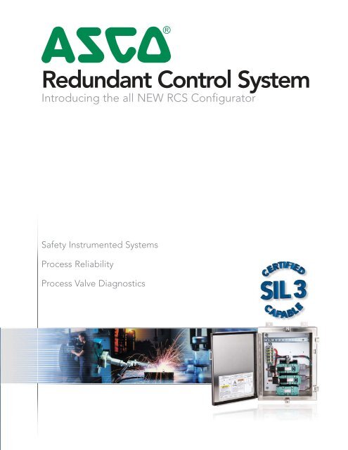
4<strong>Redundant</strong> <strong>Control</strong> <strong>System</strong>Introducing the all NEW RCS ConfiguratorSafety Instrumented <strong>System</strong>sProcess ReliabilityProcess <strong>Valve</strong> Diagnostics
COMPLETE FUNCTIONAL SAFETY WITHENHANCED RELIABILITYThe <strong>Redundant</strong> <strong>Control</strong> <strong>System</strong> (RCS) is the only pilot valvesystem that has no single point of failure that could resultin an unwanted closure of the process valve. The<strong>Redundant</strong> <strong>Control</strong> <strong>System</strong> is certified as fit for use inSIL 3 applications with a spurious trip rate that islower than Tri-Modular <strong>Redundant</strong> logic solvers.RCS achieves a higher level of process safety andreliability by using a redundant, fault tolerantarchitecture, high diagnostic coverage, and automated testing.A keyed bypass allows on-line maintenance of the RCS withoutprocess interruption. The RCS is available in a variety of constructionsthat provide valve diagnostics through automated, partialstroke testing.The availability and reliability of RCS provides the most costeffective choice for process valve diagnostics and actuation.
DIAGNOSTIC PROCESSORWITHOUT ON-BOARD DIAGNOSTIC PROCESSORIn its simplest form, the RCS can be implemented using one digital output from the controller shared by both solenoidoperated valves and a single digital input back to the controller for a common alarm (series through all three pressureswitches) to identify a solenoid operated valve failure or maintenance bypass of the unit. Manual testing can befacilitated through panel mounted pushbuttons (two) where each pushbutton is capable of cutting power to itsassociated solenoid operated valve. Testing is performed by actuating one pushbutton at a time. For automatedoperation, the RCS is provided with two digital outputs and three digital inputs. Using a system controller, the safetyaction of the RCS is entirely controlled through the operation of the two digital outputs. Any functional testing of thesolenoid operated valves or partial stroke testing of the isolation valve is accomplished by programming the controllerusing IEC 61131 logic flow diagrams provided by <strong>ASCO</strong>.WITH ON-BOARD DIAGNOSTIC PROCESSORIn order to reduce programming and I/O requirements in the user’s controller, RCS can be supplied with an on-boarddiagnostic processor (Siemens S7-200 series). This on-board processor controls the outputs to the individual solenoidoperatedvalves and receives the diagnostic information from the pressure switch inputs. Power is supplied to theon-board PLC by user’s controller, which executes the safety action by de-energizing the output power to the on-boardprocessor. Consequently, the user’s controller is always responsible for the safety action. The on-board processor providesdiagnostic and testing information only and can be considered interference free and benign to the safety action.Watchdog relays are provided to prevent de-energizing the solenoid-operated valves due to a lack of on-boardprocessor outputs. The watchdog relays maintain power to the solenoid-operated valves, avoiding inadvertentinitiation of the safety action. The activation of the watchdog relays is detected and reported by the on-board processor.In the case of a total loss of the on-board processor, loss of communications from the on-board processor or loss of thepulse from the on-board processor, digital output is detected and annunciated.Two temperature ranges for the on-board processor are available:Standard: 32˚F to 131˚F (0˚C to 55˚C), Extended Temperature: -13˚F to 158˚F (-25˚C to 70˚C)CONFIGURATIONNORMALLY CLOSED VERSIONOperation: The normally closed RCS operates like a standard normally closed 3/2 solenoid operated valve.Application: The majority of emergency shut down valves are required to close in order to achieve the specified safestate for the process under control (i.e. shut off flow) and they are specified “fail safe” (spring to the safe state) whichrequires that the solenoid operated valves vent the process valve actuator allowing the process valve to move to aspecified safe state on loss of power.NORMALLY OPEN VERSIONOperation: The normally open RCS operates like a standard normally open 3/2 solenoid operated valve.Application: The majority of emergency vent valves are required to open in order to achieve the specified safestate for the process under control (i.e. vent off pressure). In order to prevent opening of the process valve dueto loss of instrument air, the user may choose to specify the process valve as air to open spring return closed. Tomove the process valve to the safe state requires the solenoid valves to apply air to the process valve actuatorwhen they are de-energized. This configuration also fulfills the requirement that the process valve will move tothe specified safe state on loss of power.DOUBLE ACTING VERSION (Available in 2oo2D operation.)Operation: The double acting RCS operates like a 4/2 valve controlling air pressure to opposite sides of a pistontype actuator.Application: The user must determine the desired position (open or closed) for the process valve on loss of power (i.e.fail close/fail open). If the desired “fail” state for the valve is open, the normally open solenoid valve of the doubleacting RCS will control the air to the side of the process valve actuating cylinder that will drive the process valve shutand the normally closed solenoid operated valve of the double acting RCS will control the air to the side of the processvalve actuating cylinder that will vent and allow the process valve to shut.
OPERATIONAL MODES2oo2D MODEIn the 2oo2D mode, both solenoids must de-energize for shutdown. Pressure switches are used to individuallyalarm if either solenoid valve goes to the vent state when not commanded, there by reducing the potential forspurious trips. The pressure switches are also used for signaling during automatic, on-line testing.1oo1HS MODEIn the 1oo1HS mode, only one solenoid valve is on-line during normal operation. Any spurious trip of the on-linesolenoid valve is detected by the logic solver, due to a signal being sent from an associated pressure switch. Theresponse to the trip is to energize the second solenoid valve thereby maintaining air supply to the block valve.For functional testing, both solenoid valves are energized. Each solenoid valve is de-energized individually withpressure switch confirmation of successful venting. No bypassing is required for functional testing. With thisconfiguration, RCS achieves the safety availability of a single solenoid valve, the reliability of a two-out-of-twovoted solenoid operated valve configuration and has received SIL 3 certification.OPTIONAL FEATURES<strong>ASCO</strong> offers many standard optional features. These features are available individually as well as in many differentcombinations. Special constructions containing customer specified features are also available. Please contact your<strong>ASCO</strong> representative for availability.Some optional features automatically come with lights and/or push buttons located in pre-assigned locations for localinitiation and local indication. They are as follows:• Common alarm includes (1) green light• Local initiation of SOV test includes (1) push button and (2) red lights• Local initiation of partial stroke test includes (1) push button and (1) red light• Local manual reset includes (1) red lighted push button• Local initiation of bypass includes (1) red lightCustomer Selected Lights and Push ButtonsSpace for up to (4) additional customer selected lights and/or push buttons is available. The location of these lightsand push buttons can be identified by placing your computer cursor on an option. This will result in this optionbeing displayed on the cabinet view.
4<strong>ASCO</strong> simplified the RCS product selection process with an online catalog number configurator. Once you havedetermined the features required, you can easily construct a catalog number by clicking on each feature required andthen clicking the View Details button. A second screen appears providing the product catalog number, productattributes, and various drawings. The configurator is programmed to accept only valid constructions.In addition to creating a catalog number, the configurator can also decipher a catalog number. Type a valid 5RC or5LC catalog number into the window next to the Enter Catalog Number button (CAPs only). The configuratorautomatically highlights the appropriate construction features.In order to use the online configurator go to: www.ascovalve.com/RCSConfigurator
www.ascovalve.comCanadaTel 519-758-2700AustraliaTel (61) 2-9-451-7077BrazilTel (55) 11-4195-5333MexicoTel (52-1) 728-28-51-238FranceTel (33) 1-47-14-32-00GermanyTel (49)-7237-9960United KingdomTel (44) 1695-724270ChinaTel (852) 2-343-8580SingaporeTel (65) 6556-1100JapanTel (81) 798-65-6361<strong>ASCO</strong> <strong>Valve</strong>, Inc. • 800.972.2726 • www.ascovalve.comV7363 R3