Fuel Oil Valves 8377 3/8 and 1 - ASCO Valve Inc.
Fuel Oil Valves 8377 3/8 and 1 - ASCO Valve Inc.
Fuel Oil Valves 8377 3/8 and 1 - ASCO Valve Inc.

You also want an ePaper? Increase the reach of your titles
YUMPU automatically turns print PDFs into web optimized ePapers that Google loves.
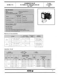
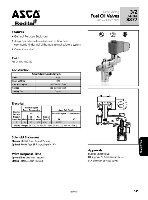
4Direct Acting<strong>Fuel</strong> <strong>Oil</strong> <strong><strong>Valve</strong>s</strong>3/8" <strong>and</strong> 1/2" NPT3/2SERIES<strong>8377</strong>Features• General Purpose Enclosure• 3-way operation allows diversion of flow fromcommercial/industrial oil burners to recirculatory system• Zero differential^ # %Fluid<strong>Fuel</strong> <strong>Oil</strong> up to 1500 SSUConstructionBodySeals <strong>and</strong> DiscCore <strong>and</strong> PlugnutSpringsShading Coil<strong>Valve</strong> Parts in Contact with FluidsBrassFKM430F Stainless Steel302 Stainless SteelCopperElectricalSt<strong>and</strong>ardCoil <strong>and</strong>Class ofInsulationWatt Rating <strong>and</strong>Power ConsumptionSpare Coil FamilyACGeneral Purpose ExplosionproofWattsVAHoldingVAInrushAmbientTemp.°F AC ACF 15.4 27 160 32 to 115 099257 -St<strong>and</strong>ard Voltages: 24, 120, 240 volts AC, 60 Hz (or 110, 220 volts AC, 50 Hz).Solenoid EnclosuresSt<strong>and</strong>ard: RedHat Type 1 General Purpose.Optional: RedHat Type 3R Rainproof (prefix “R”).<strong>Valve</strong> Response TimeOpening Time: Less than 1 secondClosing Time: Less than 1 secondApprovalsUL listed Shutoff <strong>Valve</strong>.FM Approved <strong>Oil</strong> Safety Shutoff <strong><strong>Valve</strong>s</strong>CSA Electrically Operated <strong><strong>Valve</strong>s</strong>COMBUSTION<strong>8377</strong>R1395
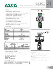
3/2SERIES<strong>8377</strong> 4Specifications (English units)Operating PressureDifferential (psi)<strong>Fuel</strong> <strong>Oil</strong> up to 1500 SSU ➁Dimensions inches (mm)Max. FluidTemp.°FPipe Orifice CvInletAgency WattageSize Size FlowPositionConst.(ins.) (ins.) Factor Min. Max. Fluid Ambient 1 Catalog Number Ref. UL FM CSA ACCOMBUSTION (<strong>Fuel</strong> <strong>Oil</strong>) - NORMALLY CLOSED3/8 1/4 1.0 0 100 265 115 A <strong>8377</strong> 001 1 ❍ ❍ ❍ 15.43/8 1/4 1.0 0 100 265 115 B <strong>8377</strong> 003 1 ❍ ❍ ❍ 15.43/8 1/4 1.0 0 100 265 115 C <strong>8377</strong> 005 1 ❍ ❍ ❍ 15.43/8 1/4 1.0 0 100 265 115 D <strong>8377</strong> 013 1 ❍ ❍ ❍ 15.41/2 1/4 1.0 0 100 265 115 A <strong>8377</strong> 007 1 ❍ ❍ ❍ 15.41/2 1/4 1.0 0 100 265 115 B <strong>8377</strong> 009 1 ❍ ❍ ❍ 15.41/2 1/4 1.0 0 100 265 115 C <strong>8377</strong> 011 1 ❍ ❍ ❍ 15.41/2 1/4 1.0 0 100 265 115 D <strong>8377</strong> 015 1 ❍ ❍ ❍ 15.4❍ = Safety Shutoff <strong>Valve</strong>. 1 Before ordering, refer to Diagram A below for description of inlet positions.➁ <strong>Valve</strong> intended for burner control with low pressure drop when energized. For other applications, be sure pressure drop when energized does not exceed 65 psi.Specifications (Metric units)Operating PressureDifferential (bar)<strong>Fuel</strong> <strong>Oil</strong> up to 1500 SSU ➁Max. FluidTemp.°CPipe Orifice KvInletAgency WattageSize Size FlowPositionConst.(ins.) (mm) (m 3 /hr) Min. Max. Fluid Ambient 1 Catalog Number Ref. UL FM CSA ACCOMBUSTION (<strong>Fuel</strong> <strong>Oil</strong>) - NORMALLY CLOSED3/8 6 0.9 0 6.9 129 46 A <strong>8377</strong> 001 1 ❍ ❍ ❍ 15.43/8 6 0.9 0 6.9 129 46 B <strong>8377</strong> 003 1 ❍ ❍ ❍ 15.43/8 6 0.9 0 6.9 129 46 C <strong>8377</strong> 005 1 ❍ ❍ ❍ 15.43/8 6 0.9 0 6.9 129 46 D <strong>8377</strong> 013 1 ❍ ❍ ❍ 15.41/2 6 0.9 0 6.9 129 46 A <strong>8377</strong> 007 1 ❍ ❍ ❍ 15.41/2 6 0.9 0 6.9 129 46 B <strong>8377</strong> 009 1 ❍ ❍ ❍ 15.41/2 6 0.9 0 6.9 129 46 C <strong>8377</strong> 011 1 ❍ ❍ ❍ 15.41/2 6 0.9 0 6.9 129 46 D <strong>8377</strong> 015 1 ❍ ❍ ❍ 15.4❍ = Safety Shutoff <strong>Valve</strong>. 1 Before ordering, refer to Diagram A below for description of inlet positions.➁ <strong>Valve</strong> intended for burner control with low pressure drop when energized. For other applications, be sure pressure drop when energized does not exceed 4.5 bar.Const. Ref. 1Flow DiagramsCOMBUSTIONØ7/8 KNOCKOUTFOR 1/2 CONDUITCONNECTION(2 HOLES IN LINE)2-7/32 (56)6-11/16 (170)BBPPAASOLENOID ENERGIZED SOLENOID DE-ENERGIZEDDiagram A"A" POSITION"B" POSITION"D" POSITIONBYPASSCONNECTION1 1/2 (38)"C" POSITION3-3/4 (95)5 (127)3/8 OR1/2 NPT3 PLACES1-19/32 (40)2-1/2 (64)MOUNTING BRACKETSTANDARD2X Ø.344FOR MOUNTINGMust be mounted with solenoid vertical <strong>and</strong> upright.1-13/16 (46)396<strong>8377</strong>R1