Functional Safety Solutions (V7666R3) - ASCO Valve Net
Functional Safety Solutions (V7666R3) - ASCO Valve Net
Functional Safety Solutions (V7666R3) - ASCO Valve Net
- No tags were found...

You also want an ePaper? Increase the reach of your titles
YUMPU automatically turns print PDFs into web optimized ePapers that Google loves.
3-Way Pilot <strong>Valve</strong>s (8320 Series)PipeSize(in)OrificeSize(in)Cv FlowFactorOperating PressureDifferential (psi)Max. DCMin.FluidandAmbientTemp. °FPorts1-2Ports2-3Air-InertGas WaterLt. Oil @ 45SSUUNIVERSAL OPERATION (Pressure at any port) – SIL 3 Capable, Certified by Exida 1Max.FluidTemp.°FMaxAmbientTemp.°FBrass BodyCatalog NumberConst.Ref.Watt Rating/Class of Coil316 Stainless Steel Body InsulationConst.Catalog Number Ref. AC DC1/4 1/4 0.49 0.56 150 150 150 -4 176 131 8327G041 16 - - 12.0/F 11.6/F1/4 1/4 0.49 0.56 150 150 150 -4 248 131 - - EV8327G042 16 12.0/F 11.6/F1/4 1/4 0.49 0.56 150 - - -40 131 131 8327G051 16 - - 12.0/F 11.6/F1/4 1/4 0.49 0.56 150 - - -40 131 131 - - EV8327G052 16 12.0/F 11.6/F1 <strong>Safety</strong> manual and FMEDA (Failure Modes Effects and Diagnostic Analysis) report available. SIL 3 Capable, Certified by Exida, only valid when used as Normally Closed.PipeSize(in)OrificeSize(in)Cv FlowFactorOperating PressureDifferential (psi)Air-InertFluidandAmbient Temp °FAluminum BodyMin. Max. Min. Max. AC Max. DC Catalog NumberNORMALLY CLOSED – OPEN FRAME DIN COIL – SIL 3 Capable, Certified by Exida 1Watt Rating/ Class ofCoilInsulationConst.Ref. AC DC1/4 1/4 0.86 30 150 5 140 140 SC8551A005MS 17 2.5/F 3.0/F1/2 1/2 3.7 30 150 -15 140 140 SC8553A005MS 17 5.0/F 6.9/FNORMALLY CLOSED – WATERTIGHT ENCLOSURE – SIL 3 Capable, Certified by Exida 11/4 1/4 0.86 30 150 5 140 77 WT8551A005MS 17 6.3/F 6.9/F1/2 1/2 3.7 30 150 -15 140 77 WT8553A005MS 17 6.3/F 6.9/FNORMALLY CLOSED – EXPLOSIONPROOF ENCLOSURE – SIL 3 Capable, Certified by Exida 11/4 1/4 0.86 30 150 5 104 77 EF8551A005MS 17 6.3/F 6.9/F1/2 1/2 3.7 30 150 -15 104 77 EF8553A005MS 17 6.3/F 6.9/F1 <strong>Safety</strong> manual and FMEDA (Failure Modes Effects and Diagnostic Analysis) report available.PipeSize(in)OrificeSize(in)Cv FlowFactorMax. ACOperating PressureDifferential (psi)Air-InertOperating PressureDifferential (psi)Min. Max. AC Max. DCNORMALLY CLOSED – SIL 3 Capable, Certified by Exida 1Fluid Temp. ˚F Ambient Temp. ˚F Aluminum Body Brass BodyMax.ACMax. DCMax.DCMin.Min.Fluid andAmbientMax.AC316LStainless Steel BodyWatt Rating/Class of CoilInsulationMax.Const.DC Catalog Number Ref. AC DC1/4 1/4 0.86 30 145 120 140 120 5 125 104 8551G405 - - 18 10.1/F 11.6/F1/4 1/4 0.86 30 145 120 140 120 -40 125 104 - EF8551G407➂ - 18 10.1/F 11.6/F1/4 1/4 0.86 30 145 120 140 120 -40 125 104 - - EV8551G4132 18 10.1/F 11.6/F1/2 1/2 3.7 30 145 120 140 120 5 125 104 8553G405 - - 18 10.1/F 11.6/F1/2 1/2 3.7 30 145 120 140 120 -40 125 104 - - EV8553G4132 18 10.1/F 11.6/F1 <strong>Safety</strong> manual and FMEDA (Failure Modes Effects and Diagnostic Analysis) report available.2 Stainless steel construction supplied standard with EV solenoid.➂ Brass construction supplied standard with EF solenoid.Max.FluidTemp. ˚FMax.AmbientTemp. ˚FBrass BodyStainless Steel BodyWatt Rating/Class of CoilInsulation 1PipeSize(in)OrificeSize(in)CvFlowFactorAir-InertGas WaterLt. Oil@ 300SSUAir-InertGas WaterLt. Oil@ 300SSU Temp. °F AC DC AC DCCatalogNumberConst.Ref.CatalogNumberConst.Ref. AC DCNORMALLY CLOSED (Closed when de-energized) – SIL 3 Capable, Certified by Exida ➃1/8 3/64 0.06 200 200 200 200 200 200 32 180 120 125 104 8320G132 12 8320G142 2 12 6.1F 10.6/F1/8 1/16 0.09 150 125 125 125 125 125 32 180 120 125 104 8230G013 12 8320G045 2 12 6.1F 10.6/F1/8 1/16 0.09 210 225 225 160 160 160 32 200 150 125 104 8320G215 13 8320G224 ➂ 13 17.1/F 11.6/F1/8 3/32 0.12 100 100 100 100 100 100 32 180 120 125 104 8320G015 12 8320G047 2 12 6.1F 10.6/F1/8 3/32 0.12 150 150 150 115 115 115 32 200 150 125 104 8320G216 13 8320G225 ➂ 13 10.1/F 11.6/F1/8 1/8 0.21 40 40 40 40 40 40 32 180 120 125 104 8320G017 12 8320G049 2 12 6.1F 10.6/F1/8 1/8 0.21 85 85 85 60 60 60 32 200 150 125 104 8320G217 13 8320G226 ➂ 13 10.1/F 11.6/F1/4 1/16 0.09 210 225 225 160 160 160 32 200 150 125 104 8320G182 14 8320G231 ➂ 15 17.1/F 11.6/F1/4 3/32 0.12 150 150 150 115 115 115 32 200 150 125 104 8320G184 14 8320G202 2➂ 15 10.1/F 11.6/F1/4 1/8 0.25 85 85 85 60 60 60 32 200 150 125 104 8320G186 14 8320G203 2➂ 15 10.1/F 11.6/F1/4 11/64 0.35 45 45 45 25 25 25 32 200 150 125 104 8320G188 14 - - 10.1/F 11.6/F1 On 50 hertz service, the watt rating for the 6.1/F solenoid is 8.1 watts; the watt rating for the 9.1/F solenoid is 11.1 watts.2 Can be used for dry natural gas service with the EF or EV prefix.➂ Constructions standard rated -40˚F ambient temperature. EFX prefix and TPL # not required➃ <strong>Safety</strong> manual and FMEDA (Failure Modes Effects and Diagnostic Analysis) report available.3-Way Pilot <strong>Valve</strong>s (8327 Series)3-Way Pilot <strong>Valve</strong>s (8551/8553 Series)3-Way Pilot <strong>Valve</strong>s (8551/8553 Series)5
Dimensions: inches [mm]Const. Ref. 10Const. Ref. 111/8 PIPE THREAD3.06 [78]2.06 [52]3CONDUIT1/2" NPT1.95 [50]1/8 PIPE THREAD3.06 [78]2.06 [52]3CONDUIT1/2" NPT1.95 [50]1.71[44]2.78[71]3.09[78]1.80[46]2.87[73]3.23[82]121/8 PIPE THREAD1.19 [30] 1.19 [30](2 PLACES)1 2 1/4 PIPE THREAD1.56 [40] (2 PLACES)1.29 [33].30 [7.6].59 [15].87 [22].34 [8.7].69 [18].87 [22]M5 THREAD.30 [7.6] MIN.FULL THREAD DEPTH2 HOLES FOR MOUNTINGM5 THREAD.30 [7.6] MIN. FULL THREAD DEPTH2 HOLES FOR MOUNTINGConst. Ref. 121/2 NPT1.69 [43].44 [11]12.09 [2.3]2 PLACES31.32[34]2.18[55]3.15[80]R.09 [2.3]4 PLACESFOR MOUNTING2 MOUNTING HOLES.164 [4] THD CUTTINGSCREW1/8 NPT3 PLACES.44 [11]Ø 1.19 [30]1.30[33].63[16]2 MOUNTING HOLESFOR .164 [4.2] THREADCUTTING SCREW.440 [11.2].440 [11.2]R.090 [2.3].090 [2.3]2 PLACESMOUNTING BRACKET8
Dimensions: inches [mm]Const. Ref. 133.03[77]2.03[52]1.95[50]1/2 NPT123.64[93]1.69[43] 2.66[68]231/8 NPT3 PLACES1.19[30]2 MOUNTING HOLESFOR .164 [4.2] THREADCUTTING SCREW.440 [11.2].090 [2.3]2 PLACES1.30 [33].440 [11.2]R.090 [2.3]212299-001SHOWING MOUNTING BRACKET ONLY212299-001Const. Ref. 141/2 NPT1.95 [50]2.73 [69]1.75 [45]3.74 [95].37 [9]123.44 [11]1.69 [43]2 MOUNTING HOLES.31 [8] DEEP FOR.164 [4] THD CUTTING SCREW1/4 NPT3 PLACES1.40 [36].81 [21]Const. Ref. 151.95 [50]1/2 NPT2.74 [70]1.76 [45]3.73 [95]1 2 31/4 NPT3 PLACESØ 1.44 [37].72 [18]1.81 [46]MOUNTING BRACKETWITH Ø .28 [7] HOLES 2 PLACES(STANDARD ON THIS CONSTRUCTION)9
Dimensions: inches [mm]Flow DiagramsOperation De-Energized EnergizedNormallyClosedPressureat 3132132Const. Ref. 163.03 [77]2.04 [52] 1.95 [50]1/2 NPTNormallyOpenPressureat 1UniversalPressure atAny Port13132 132 13223.89[99]3.45[85].94[24]1322.01 [51].47 [12]2 MOUNTING HOLESØ.216 [Ø5.5].51 [13]21.18 [30]1/4 NPT3 PLACESIMPORTANT: <strong>Valve</strong>s may be mounted in any position.Const. Ref. 17Series 8551 8553NPT 1/4 1/2L1 5.69 (145) 6.70 (170)H1 1.10 (28) 1.58 (40)W 1.77 (45) 2.85 (72)H131NOTE: <strong>Valve</strong> shown with CM22DIN terminal coil and connector.Connector sold separately.WL1Series 8551 8553NPT 1/4 1/2L1 1 5.12 (132) 6.00 (153)H2 4.38 (111) 4.77 (121)H1 1.10 (28) 1.58 (40)W 1.77 (45) 2.85 (72)1 Manual override option MH adds .250" (6.4),MS option adds .468" (11.9) to each solenoid endcap.H2Const. Ref. 183.02 [76.7]2.03 [51.6]3 1H1W1/8 NPT AUX. PRESSURE PORTL110
Manual Reset and Redundant Coil Pilot <strong>Valve</strong>sOperating PressureDifferential (psi)FluidTemp. °FWatt Rating/ Classof Coil Insulationper SolenoidPipeSize(in)OrificeSize(in)Cv FlowFactor Pilot Min. Pilot Max. Main Max. Min. Max.Max.AmbientTemp. ˚FCatalogNumberConst.Ref. Body Material Pilot Construction AC DC3/2 Redundant Coil Pilot <strong>Valve</strong>s1/4 3/64 .04 - - 150 -40 140 140 EV8323G352 19 Stainless Steel Normally Closed - 1.4/F1/4 3/64 .04 - - 150 -40 140 140 EV8323G353 19 Stainless Steel Normally Open - 1.4/F1/4 3/64 .04 - - 150 -4 200 125 EV8323G052 20 Stainless Steel Normally Closed 10.1/F -1/4 3/64 .04 - - 150 -4 200 125 EV8323G053 20 Stainless Steel Normally Open 10.1/F -1/4 5/16 1.5 1 150 150 -4 180 125 EF8323G060 21 Brass Normally Closed 10.1/F -1/4 5/16 1.5 1 150 150 -4 180 125 EV8323G080 21 Stainless Steel Normally Closed 10.1/F -1/4 5/16 1.5 1 150 150 -4 180 125 EV8323G082 21 Stainless Steel Normally Open 10.1/F -1/4 5/16 1.5 1 150 150 -4 140 140 EV8323G380 22 Stainless Steel Normally Closed - 1.4/F1/4 5/16 1.5 1 150 150 -4 140 140 EV8323G382 22 Stainless Steel Normally Open - 1.4/F1/2 5/8 4 1 150 150 -4 180 125 EV8323G081 23 Stainless Steel Normally Closed 10.1/F -1/2 5/8 4 1 150 150 -4 180 125 EV8323G083 23 Stainless Steel Normally Open 10.1/F -1/2 5/8 4 1 150 150 -4 140 140 EV8323G381 24 Stainless Steel Normally Closed - 1.4/F1/2 5/8 4 1 150 150 -4 140 140 EV8323G383 24 Stainless Steel Normally Open - 1.4/F3/2 Tamper Proof Manual Reset <strong>Valve</strong>s – SIL 3 Capable, Certified by Exida 21/4 5/16 1.5 25 125 150 -4 180 125 EV8308G060 25 Stainless Steel No Voltage Release (NVR) 10.1/F -1/4 5/16 1.5 25 125 150 -4 140 140 EV8308G360 25 Stainless Steel No Voltage Release (NVR) - 1.4/F1/2 5/8 4 25 125 150 -4 180 125 EV8308G061 26 Stainless Steel No Voltage Release (NVR) 10.1/F -1/2 5/8 4 25 125 150 -4 140 140 EV8308G361 26 Stainless Steel No Voltage Release (NVR) - 1.4/F3/2 High Shock Manual Reset <strong>Valve</strong>s – SIL 3 Capable, Certified by Exida 23/8 1/4 0.45 25 125 125 -40 140 140 EV8308G385 27 Brass No Voltage Release (NVR) - 1.4/F3/8 1/4 0.45 25 125 125 -40 140 140 EV8310G385 27 Brass Electrically Tripped (TSO) - 1.4/F3/8 1/4 0.45 25 125 125 -4 200 125 EV8308G085 27 Brass No Voltage Release (NVR) 10.1/F -3/8 1/4 0.45 25 125 125 -4 200 125 EV8310G085 27 Brass Electrically Tripped (TSO) 10.1/F -3/8 1/4 0.45 25 125 125 -40 140 140 EV8308G386 28 Stainless Steel No Voltage Release (NVR) - 1.4/F3/8 1/4 0.45 25 125 125 -40 140 140 EV8310G386 28 Stainless Steel Electrically Tripped (TSO) - 1.4/F3/8 1/4 0.45 25 125 125 -4 200 125 EV8308G086 28 Stainless Steel No Voltage Release (NVR) 10.1/F -3/8 1/4 0.45 25 125 125 -4 200 125 EV8310G086 28 Stainless Steel Electrically Tripped (TSO) 10.1/F -1 Zero minimum when valve selection gasket is in external position and proper auxiliary air pressure is applied.See graph on page 12 for main line pressure vs. pilot line pressure. Minimum 15 psi operating pressure differential when selection gasket is in the internal position.2 <strong>Safety</strong> manual and FMEDA (Failure Modes Effects and Diagnostic Analysis) report available.Dimensions: inches [mm]Const.Ref.1920Ain 1.91mm 48in 1.76mm 45Const. Ref. 19, 202.64[67]PORTMARKED '2'TUBE CONNECTSPORT '2' WITHSOLENOID ATPOSITION '3'.4.78[121]3.81 [21]2.04[52]SOL BSOL A1/2 NPT CONDUITCONN 2 PLACES1/4 ANPTCYLAASOLENOID POSITIONMARKED '3'11
Dimensions: inches [mm]Const.Ref. A B C D E F G21in 1.75 8.86 6.86 4.67 4.05 1.96 1.25mm 44 225 174 119 103 50 3222in 1.91 8.23 6.86 4.67 4.05 1.96 1.25mm 48 209 174 119 103 50 3223in 1.76 8.86 7.30 4.84 4.22 2.16 1.66mm 45 225 185 123 107 55 4224in 1.91 8.23 7.30 4.84 4.22 2.16 1.66mm 48 209 185 123 107 55 42CSOL AConst. Ref. 21, 22, 23, 24ALC OFCONDUITSOL B.88 [22]Main Line Pressure vs. Pilot Line PressureAUXPILOT LINE PRESSURE (psi)12010690756045301500 15 30 45 60 75 90 105 120 135 150MAIN LINE PRESSURE (psi)EXHPRESSBDE .31 [8]F0.28 [7]4 MOUNTING HOLESG2 PLACESConst.Ref. A B C D E F G25in 11.25 6.95 6.56 4.67 4.05 1.96 1.25mm 286 177 167 119 103 50 3226in 11.50 6.38 6.62 4.82 4.20 2.08 1.66mm 292 162 168 123 107 53 42CYLBOTTOM VIEW (PILOT VALVE NOT SHOWN)Const. Ref. 25, 26BMAXCMAX131/2 NPT 2AMAX1/4 TUBE31/4 ANPT21DE .31 [8]F0.28 [7]4 MOUNTING HOLESG2 PLACESCYLBOTTOM VIEW (PILOT VALVE NOT SHOWN)12
Dimensions: inches [mm]Const.Ref. A B C D E F G H I J27in 10.04 14.24 11.43 6.56 1.38 2.05 7.59 1.44 1.01 2.11mm 255 362 290 167 35 52 193 36 26 5428BodyMaterialBrassin 12.08 14.09 11.28 6.72 1.24 2.03 8.37 1.88 1.83 2.19 Stainlessmm 307 358 286 171 31 51 213 48 46 56 SteelConst. Ref. 27, 28B3.77 [96]C1/4 NPTLATCHEDAUNLATCHEDSHOWN WITHOPTIONAL POSITIONINDICATOR SWITCH1.03 [26]PORT13.41 [87]DE F 1/2 NPTGLATCHEDR.17 [4]2 PLACESFOR MOUNTINGHPORT2 PORT3IJ3/8 NPT3 PLACES2.00 [51]13
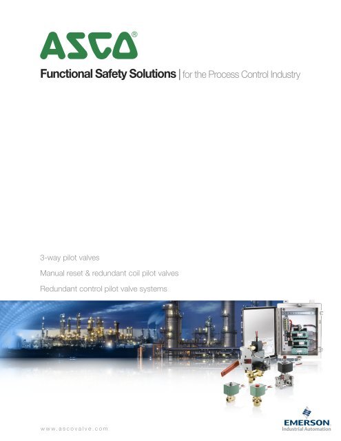
Redundant Control Pilot <strong>Valve</strong> Systems<strong>ASCO</strong> simplified the RCS product selection process with an online catalog number configurator. Once you havedetermined the features required, you can easily construct a catalog number by clicking on each feature required andthen clicking the View Details button. A second screen appears providing the product catalog number, productattributes, and various drawings. The configurator is programmed to accept only valid constructions.In addition to creating a catalog number, the configurator can also decipher a catalog number. Type a valid 5RC or5LC catalog number into the window next to the Enter Catalog Number button (CAPs only). The configuratorautomatically highlights the appropriate construction features.In order to use the online configurator go to: www.ascovalve.com/RCSConfigurator5RC027BFQ4E2Z0CEnter Catalog Number Reset View DetailsTo ensure that you are familiar with the RCS product line, we recommend that you read the RCS catalog prior to designing a product.Design a Redundant Control SystemATEX Cert O&M Guide View <strong>Safety</strong> Manual View RCS Catalog*** * *Indicates a required attributeNoneStandard: 32˚F to 131˚F (0˚C to 55˚C)On board Diagnostic ProcessorExtended Temperature: -13˚F to 158˚F (-25˚C to 70˚C)*Normally ClosedNormally OpenDouble ActingConfigurationInformationEnclosure Material System Voltage Operational Mode304 Stainless Steel12 VDC316 Stainless Steel24 VDCComposite (Fiberglass)48 VDC120 VDC120/60-110/5024 VDC Intrinsically Safe230/50-240/50Optional FeaturesEnergized to TripDe-Energized to Trip1oo1HS De-Energized to Trip2oo2 De-Energized to TripCommon AlarmModbus 485 CommunicationLocal Initiation of Sov TestLocal Initiation of Partial Stroke TestLocal Manual ResetBypass InidcationMidstroke Limit SwitchSilver Contacts for Relay LogicSIL CertificationFull Stroke Limit SwitchDual Power SourcesAnalog Input ModuleTwo Analog Input ModulesCabinet HeaterLever Type BypassShutoff for Modulatd Control <strong>Valve</strong>sNo BypassATEX CertificationAdditional Lights and Push ButtonsPOne Green LightTwo Green LightsThree Green LightsFour Green LightsOne Red LightTwo Red LightsThree Red LightsFour Red LightsOne Green & One Red LightTwo Green & One Red LightThree Green & One Red LightOne Green & Two Red LightsOne Green & Three Red LightsTwo Green & Two Red LightsOne Push ButtonTwo Push ButtonsThree Push ButtonsFour Push ButtonsEnter Catalog Number Reset View Details14
Global ContactsAustraliaTel (61) 2-9-451-7077CanadaTel (1) 519-758-2700FranceTel (33) 1-47-14-32-00JapanTel (81) 798-65-6361SingaporeTel (65) 6556-1100BrazilTel (55) 11-4208-1700ChinaTel (86) 21-3395-0000GermanyTel (49)-7237-9960MexicoTel (52) 55-5809-5640United KingdomTel (44) 1695-713600<strong>ASCO</strong> <strong>Valve</strong>, Inc. | Tel (1) 800.972.2726 | www.ascovalve.com | e-mail: info-valve@asco.com07/12 — V7666 R3