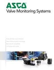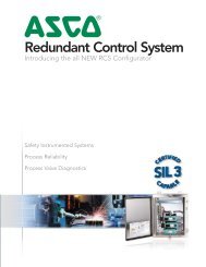
Redundant Control Systems Catalog (V7363R6) - ASCO Valve Net
Redundant Control Systems Catalog (V7363R6) - ASCO Valve Net
Redundant Control Systems Catalog (V7363R6) - ASCO Valve Net

You also want an ePaper? Increase the reach of your titles
YUMPU automatically turns print PDFs into web optimized ePapers that Google loves.
DIAGNOSTIC PROCESSORWITHOUT ON-BOARD DIAGNOSTIC PROCESSORThe RCS consists of two solenoid valves (SOV 1, SOV 2), a pneumatically operated bypass valve, and three pressureswitches (PS1, PS2, PS3). Two pressure switches provide feedback status of the solenoid valves (SOV 1, SOV 2) duringon-line testing (Solenoid <strong>Valve</strong> Test, Partial Stroke Test) and also monitor the status of SOV 1 and SOV 2 (FailureDetection), the third pressure switch detects bypass status. Using a system controller (DCS controller or Safety PLC), therequired I/O count uses two digital outputs (SOV 1, SOV 2) and three digital inputs (PS1, PS2, PS3) for the implementationof redundant logic (2oo2 or 1oo1 HS). Functional testing of the solenoid operated valves or partial stroke testingof the isolation valve (Critical <strong>Valve</strong>) is accomplished by programming the controller using IEC 61131 logic flow diagramsprovided by <strong>ASCO</strong>. In its simplest form, the RCS can be implemented using one digital output from the systemcontroller (DCS controller or Safety PLC), shared by both solenoid valves (SOV 1 and SOV 2) and a single digital inputback to the system controller for a common alarm (series through all three pressure switches) to identify a solenoidoperated valve failure or maintenance bypass of the unit.WITH ON-BOARD DIAGNOSTIC PROCESSORIn order to reduce programming and I/O requirements in the user’s controller, RCS can be supplied with an on-boarddiagnostic processor (Siemens S7-200 series). This on-board processor controls the outputs to the individual solenoidoperatedvalves and receives the diagnostic information from the pressure switch inputs. Power is supplied to theon-board PLC by user’s controller, which executes the safety action by de-energizing the output power to the on-boardprocessor. Consequently, the user’s controller is always responsible for the safety action. The on-board processor providesdiagnostic and testing information only and can be considered interference free and benign to the safety action.Watchdog relays are provided to prevent de-energizing the solenoid-operated valves due to a lack of on-boardprocessor outputs. The watchdog relays maintain power to the solenoid-operated valves, avoiding inadvertentinitiation of the safety action.CONFIGURATIONNORMALLY CLOSED VERSIONOperation: The normally closed RCS operates like a standard normally closed 3/2 solenoid operated valve.Application: The majority of emergency shut down valves are required to close in order to achieve the specified safestate for the process under control (i.e. shut off flow) and they are specified “fail safe” (spring to the safe state) whichrequires that the solenoid operated valves vent the process valve actuator allowing the process valve to move to aspecified safe state on loss of power.NORMALLY OPEN VERSIONOperation: The normally open RCS operates like a standard normally open 3/2 solenoid operated valve.Application: The majority of emergency vent valves are required to open in order to achieve the specified safestate for the process under control (i.e. vent off pressure). In order to prevent opening of the process valve dueto loss of instrument air, the user may choose to specify the process valve as air to open spring return closed. Tomove the process valve to the safe state requires the solenoid valves to apply air to the process valve actuatorwhen they are de-energized. This configuration also fulfills the requirement that the process valve will move tothe specified safe state on loss of power.DOUBLE ACTING VERSION (Available in 2oo2D operation.)10P12P23 123 13 1POperation: The double acting RCS operates like a 4/2 valve controlling air pressure to opposite sides of a pistontype actuator.Application: The user must determine the desired position (open or closed) for the process valve on loss of power (i.e.fail close/fail open). If the desired “fail” state for the valve is open, the normally open solenoid valve of the doubleacting RCS will control the air to the side of the process valve actuating cylinder that will drive the process valve shutand the normally closed solenoid operated valve of the double acting RCS will control the air to the side of the processvalve actuating cylinder that will vent and allow the process valve to shut.1221023 1
OPERATIONAL MODES2oo2D MODEIn the 2oo2D mode, both solenoids must de-energize for shutdown. Pressure switches are used to individuallyalarm if either solenoid valve goes to the vent state when not commanded, there by reducing the potential forspurious trips. The pressure switches are also used for signaling during automatic, on-line testing.1oo1HS MODEIn the 1oo1HS mode, only one solenoid valve is on-line during normal operation. Any spurious trip of the on-linesolenoid valve is detected by the logic solver, due to a signal being sent from an associated pressure switch. Theresponse to the trip is to energize the second solenoid valve thereby maintaining air supply to the block valve.For functional testing, both solenoid valves are energized. Each solenoid valve is de-energized individually withpressure switch confirmation of successful venting. No bypassing is required for functional testing. With thisconfiguration, RCS achieves the safety availability of a single solenoid valve, the reliability of a two-out-of-twovoted solenoid operated valve configuration and is SIL 3 capable.OPTIONAL FEATURES<strong>ASCO</strong> offers many standard optional features. These features are available individually as well as in many differentcombinations. Special constructions containing customer specified features are also available. Please contact your<strong>ASCO</strong> representative for availability.Some optional features automatically come with lights and/or push buttons located in pre-assigned locations for localinitiation and local indication. They are as follows:• Common alarm includes (1) green light• Local initiation of SOV test includes (1) push button and (2) red lights• Local initiation of partial stroke test includes (1) push button and (1) red light• Local manual reset includes (1) red lighted push button• Local indication of bypass includes (1) red lightCustomer Selected Lights and Push ButtonsSpace for up to (4) additional customer selected lights and/or push buttons is available. The location of these lightsand push buttons can be identified by placing your computer cursor on an option. This will result in this optionbeing displayed on the cabinet view.
GENERAL SPECIFICATIONSTotal weight: Approx. 75 lbsAir Quality: Dry instrument air, filtered to 40 microns(5 micron particulateand .3 micron coalescing filtration recommended)Ambient Temperatures:RCS-5R (without on-board diagnostic processor): -40˚F to 140˚F ( -40˚C to 60˚C)RCS-5L (with on-board diagnostic processor): 32˚F to 131˚F ( 0˚C to 55˚C)RCS-5L (for extended temperatures): -13˚F to 140˚F ( -25˚C to 60˚C)Wiring: Maximum wiring size 14 awgCv: 2.0 Typical for NCAssembly Approvals: (without on-board diagnostic processor)ATEX II 2 G Ex d e mb IICENCLOSURE304 or 316 Stainless Steel, Fiberglass Type 4, 4X, IP56SOLENOID VALVE (2 UNITS)Solenoid Operators: 1.4 watt (DC), 10.1 watt (AC), UL listedClass I, Division 2, Groups A,B,C, & D - Nonincendive;Class 1, Division 1, Groups A,B,C, & D - Explosionproof AC & DCContinuous duty (CSA certified) - DCPRESSURE SWITCH (3 UNITS)Stainless Steel Wetted Parts - FM, CSA, ATEX: EEx d IIC, CEElectrical rating: Gold contacts (std) 1 amp suppressed resistive load; .5 amp inductive load @ 28 VDCSilver contacts (opt) 5 amps suppressed resistive load; 3 amps inductive load @ 28 VDCON-BOARD DIAGNOSTIC PROCESSOR (RCS-L)European Community (CE) Low Voltage Directive 73/23/EECEN 61131-2: Programmable controllers - Equipment requirementsUL 508 Listed (Industrial <strong>Control</strong> Equipment) Registration number E75310CSA C22.2 Number 142 Certified (Process <strong>Control</strong> Equipment)FM Class I, Division 2, Groups A,B,C, & D Hazardous Locations T4A and Class I, Zone 2 IIC, T4SIL 3RCS in 1oo1HS and 2oo2D configurations is fit for use in SIL 3 applications per IEC 61508 for low demand modeapplications. For more information, consult the RCS safety manual.OPTIONSPanel lights (Class I, Div. 2), and push button (Class I, Div. 2) up to a total of 12 lights and push buttons.PNEUMATIC CONNECTIONSRecommended piping for the inlet and outlet pneumatic connections to the RCS is 1/2" stainless steel tubing.The length of tubing between the RCS and the process valve should be kept as short as possible for the fastestresponse of the process valve actuator.Normally Closed / Normally OpenInlet: 1/2" NPT, 3-150 psi max.Pilot: 1/8" NPT, 40-150 psi maxProcess: 1/2" NPTExhaust: 1/2" NPTDouble ActingInlet: 1/2" NPT, 3-150 psi max.Pilot: 1/8" NPT, 40-150 psi max.Process: (2) 1/2" NPTExhaust: 1/2" NPTOPERATIONAL RELATIONSHIP OF THE RCS TO THE PROCESS VALVEDe-energize to TripNormally Closed Normally Open Double ActingCoils Energized (Normal) Supplies air to PV Exhaust PV Supplies air to (C2), Exhaust (C1)Coils De-energized (Trip) Exhaust PV Supplies air to PV Exhaust (C2), Supplies air to (C1)Bypass Supplies air to PV Exhaust PV Supplies air to (C2), Exhaust (C1)Energize to TripNormally Closed Normally Open Double ActingCoils De-energized (Normal) Supplies air to PV Exhaust PV Supplies air to (C2), Exhaust (C1)Coils Energized (Trip) Exhaust PV Supplies air to PV Exhaust (C2), Supplies air to (C1)Bypass Supplies air to PV Exhaust PV Supplies air to (C2), Exhaust (C1)
4<strong>ASCO</strong> simplified the RCS product selection process with an online catalog number configurator. Once you havedetermined the features required, you can easily construct a catalog number by clicking on each feature required andthen clicking the View Details button. A second screen appears providing the product catalog number, productattributes, and various drawings. The configurator is programmed to accept only valid constructions.In addition to creating a catalog number, the configurator can also decipher a catalog number. Type a valid 5RC or5LC catalog number into the window next to the Enter <strong>Catalog</strong> Number button (CAPs only). The configuratorautomatically highlights the appropriate construction features.In order to use the online configurator go to: www.ascovalve.com/RCSConfigurator5RC027BFQ4E2Z0CEnter <strong>Catalog</strong> Number Reset View DetailsTo ensure that you are familiar with the RCS product line, we recommend that you read the RCS catalog prior to designing a product.Design a <strong>Redundant</strong> <strong>Control</strong> SystemATEX Cert O&M Guide View Safety Manual View RCS <strong>Catalog</strong>*** * *Indicates a required attributeNoneStandard: 32˚F to 131˚F (0˚C to 55˚C)On board Diagnostic ProcessorExtended Temperature: -13˚F to 158˚F (-25˚C to 70˚C)*Normally ClosedNormally OpenDouble ActingConfigurationInformationEnclosure Material System Voltage Operational Mode304 Stainless Steel12 VDC316 Stainless Steel24 VDCComposite (Fiberglass)48 VDC120 VDC120/60-110/5024 VDC Intrinsically Safe230/50-240/50Optional FeaturesEnergized to TripDe-Energized to Trip1oo1HS De-Energized to Trip2oo2 De-Energized to TripCommon AlarmModbus 485 CommunicationLocal Initiation of Sov TestLocal Initiation of Partial Stroke TestLocal Manual ResetBypass InidcationMidstroke Limit SwitchSilver Contacts for Relay LogicSIL CertificationFull Stroke Limit SwitchDual Power SourcesAnalog Input ModuleTwo Analog Input ModulesCabinet HeaterLever Type BypassShutoff for Modulatd <strong>Control</strong> <strong>Valve</strong>sNo BypassATEX CertificationAdditional Lights and Push ButtonsPOne Green LightTwo Green LightsThree Green LightsFour Green LightsOne Red LightTwo Red LightsThree Red LightsFour Red LightsOne Green & One Red LightTwo Green & One Red LightThree Green & One Red LightOne Green & Two Red LightsOne Green & Three Red LightsTwo Green & Two Red LightsOne Push ButtonTwo Push ButtonsThree Push ButtonsFour Push ButtonsEnter <strong>Catalog</strong> Number Reset View Details
Global ContactsAustralia (61) 2-9-451-7077Brazil (55) 11-4208-1700Canada (1) 519-758-2700China (86) 21-3395-0000Czech Republic (420) 235-090-061Dubai - UAE (971) 4 811 8200France (33) 1-47-14-32-00Germany (49) 7237-9960India (91) 44-39197300Italy (39) 02-356931Japan (81) 798-65-6361Mexico (52) 55-5809-5640<strong>Net</strong>herlands (31) 33-277-7911Singapore (65) 6556-1100South Korea (82) 2-3483-1570Spain (34) 942-87-6100United Kingdom (44) 1695-713600<strong>ASCO</strong> <strong>Valve</strong>, Inc. (USA) | Tel (1) 800.972.2726 | www.ascovalve.com | e-mail: info-valve@asco.com05/13 — <strong>V7363R6</strong>