An adaptive write word-line pulse width and voltage modulation ...
An adaptive write word-line pulse width and voltage modulation ...
An adaptive write word-line pulse width and voltage modulation ...

Create successful ePaper yourself
Turn your PDF publications into a flip-book with our unique Google optimized e-Paper software.
<strong>write</strong> operation where the number of cycles is <strong>adaptive</strong>ly<br />
determined via <strong>write</strong> completion detection, similar to the scheme<br />
used in [4]. Overall performance is improved using the multicycle<br />
<strong>write</strong> scheme.<br />
The importance of dynamic <strong>write</strong> stability has been previously<br />
discussed [5]. A replica-based <strong>adaptive</strong> stability enhancement<br />
technique [6] was proposed. While [6] is replica-based, this work<br />
describes an in situ approach (i.e., it uses actual bitcells in the<br />
SRAM array, eliminating mismatch issues). Adaptive WWL<br />
boosting for 8T SRAMs [7] was also proposed but it does not use<br />
a bit-interleaved array <strong>and</strong> hence is susceptible to soft errors. Half<br />
select prevention using a pre-read technique was proposed in [8]<br />
but does not address the large <strong>write</strong> delay margins observed at<br />
low <strong>voltage</strong>s in SRAM.<br />
2. 8-T SRAM OPERATIONS AT LOW<br />
VOLTAGES<br />
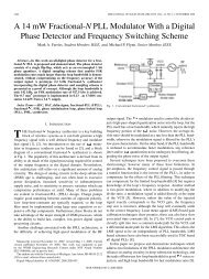
Variation increases as the supply <strong>voltage</strong> decreases. Figure 3<br />
depicts variation as supply scales. The distribution of FO4 delay<br />
is measured using 100K Monte Carlo simulations. At low <strong>voltage</strong>,<br />
performance degrades by larger variation as well as smaller I on .<br />
The performance degradation by larger variation limits lowering<br />
the supply <strong>voltage</strong> so variation compensation techniques are<br />
required for low <strong>voltage</strong> operation.<br />
Normalized Sigma over Mean<br />
7<br />
6<br />
5<br />
4<br />
3<br />
2<br />
1<br />
0<br />
0.4 0.5 0.6 0.7 0.8 0.9 1.0<br />
Supply Voltage (V)<br />
FO4 Fall<br />
FO4 Rise<br />
Figure 3. More variation exists at lower <strong>voltage</strong>.<br />
Normalized Sigma over Mean<br />
20<br />
15<br />
10<br />
5<br />
0<br />
Write<br />
Read<br />
0.5 0.6 0.7 0.8 0.9 1.0<br />
Supply Voltage (V)<br />
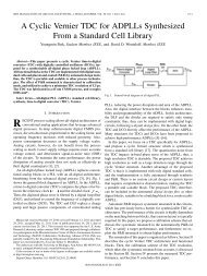
Figure 4. Write operation is critical operation at low <strong>voltage</strong><br />
because it is more vulnerable to variation.<br />
As already discussed above, the 8T SRAM bitcell is a good<br />
c<strong>and</strong>idate as a SRAM bitcell at low <strong>voltage</strong> since <strong>write</strong> operation<br />
<strong>and</strong> read operation can be separately optimized. Between read <strong>and</strong><br />
<strong>write</strong>, <strong>write</strong> operation is a critical operation at low <strong>voltage</strong><br />
because it has more variation. Figure 4 shows 40K Monte Carlo<br />
simulation results <strong>and</strong> it clearly depicts that <strong>write</strong> operation is<br />
more vulnerable to variation. Also, there are five <strong>write</strong> failures<br />
out of 40K at 0.5V while there is no read failure. Because of the<br />
five <strong>write</strong> failure at 0.5V, it is not possible to lower the supply<br />
<strong>voltage</strong> down to 0.5V.<br />
To analyze the <strong>write</strong> operation of 8T SRAM at low <strong>voltage</strong>, <strong>write</strong><br />
time is simulated using Monte Carlo simulation. Figure 5<br />
describes the definition of <strong>write</strong> time used in this work. WWL is<br />
turned on to start <strong>write</strong> operation. After some time, two internal<br />
nodes in an SRAM bitcell are crossed each other. Write time is<br />
defined as a time between WWL on <strong>and</strong> two internal nodes<br />
crossing. For successful <strong>write</strong> operation, WWL <strong>pulse</strong> <strong>width</strong> must<br />
be larger than this <strong>write</strong> time. If the <strong>write</strong> operation fails even<br />
though <strong>write</strong> time is infinitely long, static <strong>write</strong> failure happens.<br />
The Monte Carlo simulation results with 100K iterations of <strong>write</strong><br />
time as supply scales are shown in Figure 6. At 1.0V, the worst<br />
case <strong>write</strong> time is ~2.2× larger than typical. If the WWL <strong>pulse</strong><br />
<strong>width</strong> is 2.2× larger than typical <strong>write</strong> time, high yield is expected.<br />
Voltage<br />
1.2<br />
1.0<br />
0.8<br />
0.6<br />
0.4<br />
0.2<br />
0.0<br />
0.0 0.2 0.4 0.6 0.8 1.0<br />
Time<br />
Q<br />
Q_B<br />
WL<br />
Write Time<br />
Figure 5. SRAM <strong>write</strong> time is a time difference from WWL on<br />
to two internal nodes crossing.<br />
Normalized Write Time<br />
150<br />
100<br />
50<br />
0<br />
58X margin<br />
at 0.65V<br />
0.4 0.5 0.6 0.7 0.8 0.9 1.0<br />
Supply (V)<br />
Typical<br />
Maximum out of 100K<br />
2.2X margin at 1.0V<br />
Figure 6. Write time degrades as supply scales. However, the<br />
degradation of the worst case <strong>write</strong> time is much worse than<br />
typical cases. Below 0.65V, <strong>write</strong> failure happens (static <strong>write</strong><br />
failure).<br />
92


![[Sample B: Approval/Signature Sheet]](https://img.yumpu.com/34084789/1/190x245/sample-b-approval-signature-sheet.jpg?quality=85)