paper - IEEE Xplore
paper - IEEE Xplore
paper - IEEE Xplore

Create successful ePaper yourself
Turn your PDF publications into a flip-book with our unique Google optimized e-Paper software.
<strong>IEEE</strong> TRANSACTIONS ON CIRCUITS AND SYSTEMS—I: REGULAR PAPERS, VOL. 58, NO. 7, JULY 2011 1511<br />
A Cyclic Vernier TDC for ADPLLs Synthesized<br />
From a Standard Cell Library<br />
Youngmin Park, Student Member, <strong>IEEE</strong>, and David D. Wentzloff, Member, <strong>IEEE</strong><br />
Abstract—This <strong>paper</strong> presents a cyclic Vernier time-to-digital<br />
converter (TDC) with digitally controlled oscillators (DCOs), targeted<br />
for a synthesizable all-digital phase locked loop (ADPLL).<br />
All functional blocks in the TDC are implemented with digital standard<br />
cells and placed-and-routed (P&R) by automatic design tools;<br />
thus, the TDC is portable and scalable to other process technologies.<br />
The effect of P&R mismatch is characterized in calibration<br />
mode, and utilized to achieve a minimum TDC resolution of 5.5 ps.<br />
The TDC was fabricated in a 65 nm CMOS process, and occupies<br />
0.006 mm 2 .<br />
Index Terms—All-digital PLL (ADPLL), standard cell library,<br />
synthesis, time-to-digital converter (TDC), Vernier.<br />
I. INTRODUCTION<br />
R<br />
ECENT process scaling allows all-digital architectures of<br />
conventional analog applications that leverage advanced<br />
digital processes. In deep submicrometer digital CMOS processes,<br />
die area decreases proportional to the scaling factor, and<br />
operating frequency increases with reduced geometry. Also,<br />
power consumption decreases as the supply voltage scales.<br />
Analog circuits, however, do not benefit from the process<br />
scaling as much. Lower supply voltage requires more accurate<br />
voltage control, and deteriorates signal-to-noise ratio (SNR)<br />
of the circuits. To maintain the same performance, the power<br />
dissipation of analog circuits does not scale as effectively as<br />
their digital counterparts [1], [2].<br />
An all-digital phase locked loop (ADPLL) replaces conventional<br />
analog blocks in a PLL with an all-digital architecture,<br />
benefitting from the advanced digital process [3], [4]. Fig. 1<br />
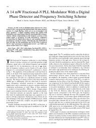
shows the general block diagram of an ADPLL. In the ADPLL,<br />
a time-to-digital converter (TDC) compares the phase error between<br />
the reference clock and the divided clock .<br />
Then, the digitized phase error is filtered by a digital loop filter<br />
(DLF), and utilized to control the frequency of a digitally controlled<br />
oscillator (DCO). The TDC and DLF replace a charge<br />
pump and large passive components of conventional analog<br />
Manuscript received October 19, 2010; revised February 12, 2011 and April<br />
28, 2011; accepted May 11, 2011. Date of publication June 16, 2011; date of<br />
current version June 29, 2011. This research was supported by the U.S. Army<br />
Research Laboratory under contract W911NF and prepared through collaborative<br />
participation in the Microelectronics Center of Micro Autonomous Systems<br />
and Technology (MAST) Collaborative Technology Alliance (CTA). Park was<br />
partially funded by the Kwanjeong Educational Foundation Scholarship. This<br />
<strong>paper</strong> was recommended by Associate Editor S. Mirabbasi.<br />
The authors are with the University of Michigan, Ann Arbor, MI 48109 USA<br />
(e-mail: yminpark@umich.edu; wentzlof@umich.edu).<br />
Color versions of one or more of the figures in this <strong>paper</strong> are available online<br />
at http://ieeexplore.ieee.org.<br />
Digital Object Identifier 10.1109/TCSI.2011.2158490<br />
Fig. 1.<br />
General block diagram of all digital PLL.<br />
PLLs, reducing the power dissipation and area of the ADPLL.<br />
Also, the digital interface between the blocks enhances testability<br />
and programmability of the ADPLL. In this architecture,<br />
the DLF and the divider are required to satisfy only timing<br />
constraints; thus, they can be implemented with digital logic<br />
circuits, following a digital design flow. On the other hand, the<br />
TDC and DCO directly affect the performance of the ADPLL.<br />
Many structures for TDCs and DCOs have been proposed to<br />
achieve high performance ADPLLs [5]–[16].<br />
In this <strong>paper</strong>, we focus on a TDC specifically for ADPLLs,<br />
and propose a cyclic Vernier structure which is synthesized<br />
from a standard cell library [17]. The quantization noise from<br />
the TDC impacts in-band phase noise of the ADPLL; thus, a<br />
high resolution TDC is desirable. The proposed TDC achieves<br />
high resolution as well as a large detection range through the<br />
cyclic Vernier structure. Another advantage of the proposed<br />
TDC is that it is implemented with only digital standard cells,<br />
and the implementation is fully automated through synthesis<br />
and P&R. There is no custom circuit design or custom layout<br />
that requires comprehensive characterization, making the TDC<br />
a portable and scalable block. The proposed TDC, therefore,<br />
can be included in the automated digital design flow as other<br />
digital blocks, suitable to be a building block for a synthesizable<br />
ADPLL.<br />
Automatic P&R imposes systematic mismatch in the circuits,<br />
which has previously been a barrier for synthesizable TDC architectures.<br />
The performance of the circuits is highly dependent<br />
on the matching between blocks, thus custom layout is typically<br />
required. In this <strong>paper</strong>, we propose a calibration scheme that addresses<br />
the systematic mismatch in the automatically P&R-ed<br />
TDC to satisfy a target performance, and furthermore we exploit<br />
the P&R mismatch to obtain higher performance.<br />
The remainder of this <strong>paper</strong> is organized as follows. Section II<br />
describes the cyclic Vernier TDC architecture and functional<br />
blocks. Then, the calibration scheme of the TDC resolution,<br />
which takes the systematic mismatch into account, is discussed<br />
in the Section III. Section IV presents the measured TDC performance,<br />
and Section V concludes this <strong>paper</strong>.<br />
1549-8328/$26.00 © 2011 <strong>IEEE</strong>
1512 <strong>IEEE</strong> TRANSACTIONS ON CIRCUITS AND SYSTEMS—I: REGULAR PAPERS, VOL. 58, NO. 7, JULY 2011<br />
II. CYCLIC VERNIER TIME-TO-DIGITAL CONVERTER<br />
A. TDC Architecture<br />
Fig. 2 shows the block diagram of a cyclic Vernier TDC [6],<br />
[7]. The goal of the TDC is to measure the time difference between<br />
the rising edges of the “Start” and “Stop” signals, which<br />
are and in the ADPLL, respectively. When the “Start”<br />
is asserted, the slow DCO starts to oscillate with a period of<br />
, and the number of oscillations is counted by the coarse<br />
counter. After an input delay of , the “Stop” signal is asserted<br />
which triggers the faster DCO to oscillate with a period<br />
of . At this time, the coarse counter is disabled, and the output<br />
of the counter represents a coarse measurement of the time between<br />
“Start” and “Stop” rising-edges . To improve the<br />
measurement accuracy, the residue of the input delay is<br />
measured by the Vernier structure. When is slightly smaller<br />
than , the time difference between rising edges of the two<br />
oscillations is reduced every cycle by the difference in periods<br />
, and the edge of the fast DCO eventually catches up<br />
to the slow DCO. By counting the number of cycles it takes for<br />
the fast DCO to catch up with the slow DCO, is measured.<br />
Then, the overall measurement of can be determined as<br />
follows:<br />
Fig. 2. (a) Block diagram of the proposed TDC and (b) timing diagram.<br />
(1)<br />
(2)<br />
where and are the number of cycles of the slow and fast<br />
oscillations, respectively, and is programmed to be<br />
much smaller than . As shown in Fig. 2, the TDC operates in<br />
two-steps; a coarse step and a fine step. The coarse step resolution<br />
is the period of the slow DCO, and the fine step resolution<br />
is the difference between the periods of the two DCOs. Note that<br />
the fine resolution does not depend on the absolute frequencies<br />
of the DCOs, but only their difference in periods. This is crucial<br />
for the calibration of mismatch between the P&R-ed DCOs<br />
discussed in Section III.<br />
Unlike conventional Vernier delay lines, the cyclic Vernier<br />
TDC adopts the ring structure to extend input range, limited only<br />
by the counter size that easily scales according to the application.<br />
Also, the linearity of the TDC improves by utilizing the periods<br />
of the DCOs, which is repetitive and consistent over operation,<br />
while the delay per stage in Vernier delay lines is more susceptible<br />
to variation and mismatch. One drawback of the cyclic<br />
Vernier TDC is a large latency of the fine step measurement. It<br />
takes one period of the fast DCO cycle to resolve a time<br />
difference of one fine step resolution . To reduce the<br />
conversion time, we adopt the two-step operation. The coarse<br />
step covers a large input time difference without any latency,<br />
and the residue of the coarse step is measured by the fine step,<br />
which is less than one cycle of the slow DCO. Also, this fine step<br />
range can be further reduced by the edge detector described in<br />
Section II-C.<br />
B. Digitally Controlled Oscillator<br />
While the previous cyclic Vernier TDC architectures [6],<br />
[7] adopt voltage controlled oscillators (VCOs), which require<br />
custom design and layout, the proposed TDC adopts DCOs<br />
Fig. 3. Digitally controlled oscillator with tristate buffers. The buffers from<br />
standard cell library are automatically placed-and-routed.<br />
that are implemented with only standard cells and P&R-ed.<br />
Fig. 3 shows the structure of the DCO. The DCO consists of<br />
three stages, and each stage is implemented with eight parallel<br />
inverting tristate buffers which are digitally controlled. Tristate<br />
buffers are available in commercial standard cell libraries.<br />
While the load capacitance at each stage is fixed by the number<br />
of buffers and wiring capacitance, the driving strength can<br />
be varied by turning on a different number of tristate buffers,<br />
thereby configuring the frequency of the DCO. Since the buffers<br />
are automatically P&R-ed by design tools, the placement and<br />
routing of the buffers are not regular as illustrated in Fig. 3.<br />
This results in systematic mismatch in the wiring capacitance,<br />
and thus a unique effective drive strength for each buffer.<br />
Though the individual drive strength cannot be controlled in<br />
the automated layout, the placement area and the wire lengths<br />
are constrained by layout algorithms, and statistics of the P&R<br />
mismatch is, to some extent, predictable at the design phase.<br />
In the proposed TDC, both the slow and fast DCOs are<br />
identically designed in a Verilog description, and automatically<br />
P&R-ed. Then, the P&R mismatch is characterized in the<br />
calibration mode, and the DCOs are configured to have slightly<br />
different periods, utilizing the P&R mismatch. The P&R mismatch<br />
provides higher resolution for the TDC, compared to<br />
the resolution obtained when the buffers are ideally matched.
PARK AND WENTZLOFF: A CYCLIC VERNIER TDC FOR ADPLLs SYNTHESIZED FROM A STANDARD CELL LIBRARY 1513<br />
Fig. 4.<br />
Structure of edge detector.<br />
Fig. 6. Measured incremental period in stage 2 of slow DCO and sorted buffer<br />
list.<br />
Fig. 5. Detection of (a) rising and (b) falling edges in the proposed edge detector.<br />
The calibration scheme and measured results are shown in<br />
Section III.<br />
C. Edge Detector<br />
Fig. 4 shows the structure of the edge detector which detects<br />
when the fast and slow oscillator edges have aligned. At the<br />
frontend of the edge detector, a flip-flop detects the phase of<br />
OSC at the rising edge of OSC . Since OSC has a slightly<br />
smaller period, it catches up with OSC every cycle, and the<br />
output of the flip-flop switches when the two edges are in line.<br />
A flip-flop from a standard cell library will have a finite setup<br />
time; therefore, the detection event occurs when the OSC edge<br />
is ahead of OSC by the setup time. This will appear as an offset<br />
in the TDC measurement, which would be digitally corrected, or<br />
potentially even ignored, in a typical ADPLL application. Another<br />
issue with the flip-flop is metastability. When two edges<br />
are apart by the setup time, the delay of the flip-flop increases<br />
and the output may not fully resolve in time; thus, the phase of<br />
OSC is not detected in that cycle period. In the TDC, however,<br />
the OSC and OSC edges get closer by the fine resolution every<br />
cycle; therefore, if a metastable condition occurs in one cycle,<br />
the output is guaranteed to settle in the very next cycle.<br />
Edge detection logic is included in the TDC to determine the<br />
direction of the phase shift (low to high, or high to low), and<br />
terminate the fine step measurement early to save power. When<br />
either edge is detected, the “Detect” signal is asserted, and the<br />
“Edge” signal indicates the direction of the detected edge. When<br />
the rising edge of OSC is detected, the “Edge” signal is asserted,<br />
and the measured time indicates the fine step measurement<br />
. On the other hand, if the falling edge of OSC is<br />
detected, “Edge” is deasserted, and half of is added to the<br />
measured time (Fig. 5).<br />
While only one edge (rising edge) is detected in conventional<br />
TDCs, the proposed edge detector detects rising and falling<br />
edges to save power consumption. Both DCOs are oscillating<br />
during the fine measurement, and the total energy consumed<br />
per TDC measurement is proportional to the measurement time.<br />
By detecting either the rising or falling edge, and terminating<br />
the fine step measurement early, the maximum measurement<br />
time is reduced by a half, and the maximum average power<br />
consumption of the TDC in an ADPLL application is reduced<br />
by as much.<br />
III. TDC CALIBRATION UTILIZING MISMATCH<br />
A key challenge in the standard cell-based implementation<br />
is systematic mismatch induced by automatic P&R. Unlike<br />
custom layout, automatic P&R generates significant mismatch<br />
in interconnects, preventing accurate modeling of the analog<br />
performance. The systematic mismatch, however, can be<br />
utilized for a higher resolution, if measured and calibrated<br />
accurately. This section proposes a calibration scheme for the<br />
fine TDC resolution.<br />
As shown in Fig. 3, there are a total of 23 tri-state buffers<br />
in each DCO (3 stages, 8 buffers/stage, and one NAND gate<br />
replacing a buffer in the first stage for startup). When all buffers<br />
are enabled, the DCO oscillates at its maximum frequency.<br />
When one of the 23 buffers is turned off, the period slightly<br />
increases. We refer to this increase in period as the incremental<br />
period (see also [18]). Fig. 6 shows the measured incremental<br />
period in stage 2 of the slow DCO. As shown in Fig. 6, each<br />
buffer has a different incremental period, highlighting the<br />
P&R mismatch. During a one-time calibration, the incremental<br />
periods of buffers are measured, and the buffers are then sorted<br />
based on the incremental period.<br />
There are two resolutions in the proposed TDC, a coarse step<br />
resolution and a fine step resolution . First, the<br />
coarse step resolution is determined by configuring the slow<br />
DCO. Fig. 7 shows the measured coarse step resolution, ranging<br />
from 170 ps to 480 ps. In Fig. 7, is increased by turning off<br />
one additional buffer at each code in the rotating order of stages.<br />
Although a DCO with three stages in 65 nm CMOS can be faster,<br />
the counters synthesized with standard cells cannot operate at<br />
the highest frequencies and becomes the limiting factor on operating<br />
frequency. The DCOs are therefore calibrated at frequencies<br />
less than 6 GHz, which is sufficient for many ADPLL<br />
applications.
1514 <strong>IEEE</strong> TRANSACTIONS ON CIRCUITS AND SYSTEMS—I: REGULAR PAPERS, VOL. 58, NO. 7, JULY 2011<br />
Fig. 7. Measured coarse step resolution.<br />
Fig. 10. Measured fine step resolution variation over supply voltage (0.9, 0.95,<br />
1, 1.05, and 1.1 V).<br />
Fig. 8.<br />
Description of fast DCO calibration.<br />
Fig. 11. Measured fine step resolution variation over temperature (0 C, 25 C,<br />
and 70 C).<br />
Fig. 9. Measured fine step resolution.<br />
When the coarse step resolution is determined, the fine step<br />
resolution is obtained by configuring the fast DCO to have a<br />
slightly lower period. Fig. 8 shows the calibration scheme to<br />
utilize P&R mismatch. When the coarse step resolution, for instance,<br />
is obtained by turning on three buffers in each stage, the<br />
calibration starts with turning on the same number of buffers<br />
in the fast DCO. First, buffers on top of the sorted lists are enabled<br />
to have the smallest impact on the period. Then, the period<br />
is slightly increased by swapping each buffer with a neighboring<br />
buffer in the list, trading buffers with lower effective<br />
drive strength for buffers with higher drive strength. Fig. 8 illustrates<br />
the calibration process from the fastest DCO configuration<br />
to the slowest DCO configuration when the number of<br />
enabled buffers per stage is maintained. The resulting range of<br />
period is around the coarse step resolution , and a desired<br />
fine step resolution can be obtained. Fig. 9 shows<br />
the measured fine step resolution, ranging from 0 to 3.3 ps. If the<br />
P&R mismatch between two DCOs is excessive, and the whole<br />
range of from the calibration is not around , the TDC resolution<br />
can be tuned by turning off a different number of buffers<br />
in each DCO. Ultimately, the performance of the TDC is determined<br />
by the fine step resolution. For ADPLL applications, we<br />
are therefore mainly interested in the calibration of the difference<br />
between two periods, and less on their absolute values.<br />
Figs. 10 and 11 show the measured fine step resolution over<br />
supply voltage and temperature variation. Although the environmental<br />
variation significantly affects the absolute value of<br />
the periods, and , we focus on the difference between periods<br />
which determines the fine resolution of the TDC. When<br />
configuring the fine resolution as 1 ps at nominal conditions,<br />
both supply voltage (0.9 V) and temperature (70 C) variation<br />
increases the resolution up to 1.5 ps. In ADPLL applications,<br />
this variation affects the stability of the ADPLL by changing the<br />
gain of the TDC block. ADPLL stability is a function of many<br />
parameters, such as the DLF and DCO gain. Thus, the stability<br />
of the ADPLL can be addressed with other ADPLL parameters,<br />
considering these environmental variations, and a high fine-step<br />
resolution is achieved over PVT variation.<br />
IV. TDC PERFORMANCE<br />
The proposed cyclic Vernier TDC was fabricated in 65 nm<br />
CMOS with an ARM standard cell library, and the micrograph<br />
and layout view of the TDC is shown in Fig. 12. All functional<br />
blocks are integrated through automatic P&R so that the<br />
TDC occupies a small area. The core area of the TDC is only<br />
0.006 mm .<br />
The input time difference in the following measurements<br />
is generated by a Tektronix AWG5012 arbitrary<br />
waveform generator with a step size of 1 ps. To eliminate input<br />
jitter from the waveform generator and the measurement setup,<br />
each value is obtained by averaging 1000 measurements in<br />
Figs. 13 and 15. Also, nonlinearity of the generated delay from<br />
the AWG5012 is first measured with a Tektronix TDS6124C<br />
oscilloscope, and then applied in the figures.<br />
A. TDC Measurement<br />
Fig. 13 shows the TDC measurement with the coarse/fine operation.<br />
The slow DCO is tuned to have a period of 220 ps by
PARK AND WENTZLOFF: A CYCLIC VERNIER TDC FOR ADPLLs SYNTHESIZED FROM A STANDARD CELL LIBRARY 1515<br />
Fig. 12.<br />
Micrograph and layout view of TDC.<br />
Fig. 13.<br />
Coarse and fine measurement of TDC.<br />
turning off the buffers. Then, the period of the fast DCO is calibrated<br />
to have a slightly lower period as described in Section III.<br />
Fig. 13 shows two different fine step resolutions, 1 ps and 5.5 ps.<br />
The coarse and fine step resolutions can be digitally configured<br />
for a desired target performance.<br />
Fig. 14(a) shows the single shot measurements of the TDC at<br />
three different time differences: 44 ps, 121 ps, and 210 ps (fine<br />
codes 15, 29, and 45 with an offset, respectively). The coarse<br />
count for these three measurements is zero. The standard deviation<br />
of the fine codes will increase with the input time difference<br />
due to accumulated jitter in the DCOs. The measured standard<br />
deviation ranges from 2.7 ps to 4.3 ps over one coarse count. Assuming<br />
an ADPLL application, accuracy of the TDC should be<br />
highest when the ADPLL is close to locking, or when the coarse<br />
code is equal to zero. Thus the maximum standard deviation of<br />
the single shot measurements is 0.78 LSB while the ADPLL is<br />
near lock.<br />
As the input time difference increases beyond one coarse<br />
count, the coarse code increases and the fine code resets to zero<br />
(following the Vernier measurement scheme). Fig. 14(b) shows<br />
the measured standard deviation over a slightly larger input time<br />
difference range. A saw tooth pattern is observed with a period<br />
of 220 ps because the fine code resets every time the coarse code<br />
increments. Fig. 14(c) shows the measured standard deviation<br />
of the sum of coarse and fine codes over a much larger range of<br />
input time differences. From this figure, standard deviation can<br />
Fig. 14. (a) Single shot measurements (total count of 10 ) over constant inputs<br />
(44 ps, 121 ps, and 210 ps) with a fine resolution of 5.5 ps, (b) standard<br />
deviation over a large range of inputs, and (c) standard deviation over the sum<br />
of coarse/fine codes. In (c), standard deviation is linear to sum of coarse/fine<br />
codes; thus, sawtooth trend is observed in (b) as coarse code increases.<br />
be approximated as linear to the sum of coarse and fine codes;<br />
thus, the fine code is dominant when the coarse code is low. This<br />
can be modeled as a function of the sum of coarse/fine codes,<br />
which fits to (3)<br />
Assuming an ADPLL application with a reference frequency<br />
of 10 MHz, the maximum range is 100 ns which is covered by<br />
the ring structure and the on-chip counters. Though the measured<br />
standard deviation at 100 ns is 23 ps, the precision improves<br />
as the ADPLL moves closer to being locked, and the<br />
TDC operates with a precision of 0.78 LSB when the ADPLL is<br />
locked with a small absolute time difference between the “Start”<br />
and “Stop” signals.<br />
B. Rising/Falling Edge Detection and TDC in ADPLL<br />
To reduce the conversion time in fine step operation, we proposed<br />
an edge detector that detects both rising and falling edges.<br />
Fig. 15 shows the measured fine codes when this scheme is applied.<br />
As shown in Fig. 15, when the fine step range is over about<br />
a half cycle of OSC , the edge detector starts to detect falling<br />
edges, rather than rising edges. In this way, the maximum conversion<br />
time of the fine step can be reduced by half.<br />
The proposed detection scheme, however, causes inaccuracy<br />
in the measurement due to duty cycle variations. Fig. 16 shows<br />
(3)
1516 <strong>IEEE</strong> TRANSACTIONS ON CIRCUITS AND SYSTEMS—I: REGULAR PAPERS, VOL. 58, NO. 7, JULY 2011<br />
TABLE I<br />
PERFORMANCE SUMMARY<br />
The precision varies over the range. The range is 11 bits for a precision less than 1 LSB.<br />
Fig. 17.<br />
Application of TDC in ADPLL.<br />
Fig. 15.<br />
edge.<br />
Measurement time reduction by detecting either of rising or falling<br />
The measured DNL and INL are less than 1 LSB when the phase<br />
error is lower than a half cycle of OSC . Though the inaccuracy<br />
of the duty cycle affects the prelock operation of the ADPLL, it<br />
is not critical for the purpose of the ADPLL when locked.<br />
In the ADPLL application, a target offset value can be subtracted<br />
from the TDC output before it is filtered by the DLF<br />
as shown in Fig. 17. This way, the ADPLL is locked around the<br />
target offset, thereby avoiding any mismatch problem in Fig. 16,<br />
and reducing power consumption which is proportional to the<br />
measured time difference.<br />
Fig. 16. Calculated output versus input time difference. In this figure, the offset<br />
from input signal paths such as cable and PCB is adjusted. The measured duty<br />
cycle is 41%, and the deviation by duty cycle variation is observed.<br />
the calculated TDC output from the coarse output code and fine<br />
output code. As can be seen in this figure, the calculated output<br />
from falling edge detection deviates from the desired values,<br />
if the duty cycle varies. Fig. 16 also shows inaccuracy around<br />
multiple cycles of OSC due to coarse/fine code ratio mismatch.<br />
The application of the proposed TDC; however, is a phase detector<br />
in ADPLLs for clock synthesis. If the PLL is programmed<br />
to be locked at a lower phase error, the phase error greater than a<br />
half cycle of OSC is used to steer the ADPLL dynamics closer<br />
to lock, and ultimately the performance is dependent only on<br />
the lower phase error measurements when the ADPLL is locked.<br />
C. Power<br />
The power dissipation in the Vernier structure depends on<br />
, and the sampling frequency of the TDC. The DCOs,<br />
which are the most power hungry blocks in the TDC, oscillate<br />
only when is measured. Therefore, the TDC operation is<br />
duty-cycled, and power dissipation is proportional to the sampling<br />
frequency.<br />
During the coarse step operation, only the slow DCO oscillates,<br />
and the measurement time is the same as the<br />
without any latency. During the fine step operation; however,<br />
both DCOs are oscillating, and the measurement time is inversely<br />
proportional to the fine step resolution, and multiplied<br />
by . The measured power consumption during coarse and fine<br />
step measurements is as follows:<br />
(4)<br />
(5)
PARK AND WENTZLOFF: A CYCLIC VERNIER TDC FOR ADPLLs SYNTHESIZED FROM A STANDARD CELL LIBRARY 1517<br />
where and is power during coarse and fine step<br />
measurements, and is sampling frequency of the TDC.<br />
V. CONCLUSION<br />
An all-digital synthesizable cyclic Vernier TDC was proposed<br />
and designed in a 65 nm CMOS process. While there<br />
has been increasing interest in all-digital implementations<br />
of conventional analog functions, the proposed TDC shows<br />
a new design methodology, where all functional blocks are<br />
implemented with standard cells, and automatically P&R-ed.<br />
The systematic mismatch by P&R is also addressed, and further<br />
exploited to obtain higher performance. The TDC can be a<br />
building block for a synthesizable ADPLL as a clock synthesizer,<br />
leveraging the automated design tools and standard cell<br />
engineering.<br />
REFERENCES<br />
[1] B. Murmann, “Digitally-assisted analog circuits,” <strong>IEEE</strong> Micro, vol. 26,<br />
no. 2, pp. 38–47, Mar.–Apr. 2006.<br />
[2] B. Murmann, “A/D converter trends: Power dissipation, scaling and<br />
digitally assisted architecture,” in Proc. <strong>IEEE</strong> Custom Integr. Circuit<br />
Conf., Sep. 2008, pp. 105–112.<br />
[3] M. Lee, M. E. Heidari, and A. A. Abidi, “A low noise, wideband digital<br />
phase-locked loop based on n tew Time-to-digital converter with subpicosecond<br />
resolution,” in Proc. <strong>IEEE</strong> VLSI Symp. Dig. Tech. Papers,<br />
Jun. 2008, pp. 112–113.<br />
[4] M. S.-W. Chen, D. Su, and S. Mehta, “A calibration-free 800 MHz<br />
fractional-N digital PLL with embedded TDC,” in ISSCC Dig. Tech.<br />
Papers, Feb. 2010, pp. 472–473.<br />
[5] R. B. Staszewski, C.-M. Hung, N. Barton, M.-C. Lee, and D. Leipold,<br />
“A digitally controlled oscillator in a 90 nm digital CMOS process<br />
for mobile phones,” <strong>IEEE</strong> J. Solid-State Circuits, vol. 40, no. 11, pp.<br />
2203–2211, Nov. 2005.<br />
[6] P. Chen, C. C. Chen, J. C. Zheng, and Y. S. Shen, “A PVT insensitive<br />
vernier-based time-to-digital converter with extended input range and<br />
high accuracy,” <strong>IEEE</strong> Trans. Nuclear Sci., vol. 54, pp. 294–302, Apr.<br />
2007.<br />
[7] J. Yu, F. F. Dai, and R. C. Jaeger, “A 12-bit vernier ring time-to-digital<br />
converter in 0.13 m CMOS technology,” <strong>IEEE</strong> J. Solid-State Circuits,<br />
vol. 45, no. 4, pp. 830–842, Apr. 2010.<br />
[8] M. Lee and A. A. Abidi, “A 9 b, 1.25 ps resolution coarse-fine time-todigital<br />
converter in 90 nm CMOS that amplifies a time residue,” <strong>IEEE</strong><br />
J. Solid-State Circuits, vol. 43, no. 4, pp. 769–777, Apr. 2008.<br />
[9] M. Z. Straayer and M. H. Perrott, “A multi-path gated ring oscillator<br />
TDC with first-order noise shaping,” <strong>IEEE</strong> J. Solid-State Circuits, vol.<br />
44, no. 4, pp. 1089–1098, Apr. 2009.<br />
[10] S. Henzler, S. Koeppe, W. Kamp, H. Mulatz, and D. Schmitt-Landsiedel,<br />
“90 nm 4.7 ps-resolution 0.7-LSB single-shot precision and 19<br />
pJ-per shot local passive interpolation time-to-digital converter with<br />
on-cihp characterization,” in <strong>IEEE</strong> Int. Solid-State Circuits Conf. Dig.<br />
Tech. Papers, Feb. 2008, pp. 548–549.<br />
[11] L. Vercesi, A. Liscidini, and R. Castello, “Two-dimensions vernier<br />
time-to-digital converter,” <strong>IEEE</strong> J. Solid-State Circuits, vol. 45, no. 8,<br />
pp. 1504–1512, Aug. 2010.<br />
[12] A. Mantyniemi, T. Rahkonen, and J. Kostamovaara, “A CMOS<br />
time-to-digital converter (TDC) based on a cyclic time domain successive<br />
approximation interpolation method,” <strong>IEEE</strong> J. Solid-State<br />
Circuits, vol. 44, no. 11, pp. 3067–3077, Nov. 2009.<br />
[13] M. Zanuso, P. Madoglio, S. Levantino, C. Samori, and A. L. Lacaita,<br />
“Time-to-digital converter for frequency synthesis based on a digital<br />
bang-bang DLL,” <strong>IEEE</strong> Trans. Circuits Syst. I, Reg. Papers, vol. 57,<br />
no. 3, pp. 548–554, Mar. 2010.<br />
[14] J.-P. Jansson, A. Mantyniemi, and J. Kostamovaara, “Synchronization<br />
in a multi-level CMOS time-to-digital converter,” <strong>IEEE</strong> Trans. Circuits<br />
Syst. I, Reg. Papers, vol. 56, no. 8, pp. 1622–1634, Aug. 2009.<br />
[15] T. Tokairin, M. Okada, M. Kitsunezuka, T. Maeda, and M. Fukaishi,<br />
“A 2.1-to-2.8-GHz low-phase-noise all-digital frequency synthesizer<br />
with a time-windowed time-to-digital converter,” <strong>IEEE</strong> J. Solid-State<br />
Circuits, vol. 45, no. 12, pp. 2582–2590, Dec. 2010.<br />
[16] Y.-H. Seo, S.-K. Lee, and J.-Y. Sim, “A 1-GHz digital PLL with a 3-ps<br />
resolution floating-point-number TDC in a 0.18- m CMOS,” <strong>IEEE</strong><br />
Trans. Circuits Syst. II, Exp. Briefs, vol. 58, no. 2, pp. 70–74, Feb. 2011.<br />
[17] Y. Park and D. D. Wentzloff, “A cyclic vernier time-to-digital converter<br />
synthesized from a 65 nm CMOS standard library,” in <strong>IEEE</strong> Proc. Int.<br />
Symp. Circuits Syst., Jun 2010, pp. 3561–3564.<br />
[18] Y. Park and D. D. Wentzloff, “An all-digital 12 pJ/pulse IR-UWB transmitter<br />
synthesized from a standard cell library,” <strong>IEEE</strong> J. Solid-State<br />
Circuits, vol. 46, no. 5, pp. 1147–1157, May. 2011.<br />
Youngmin Park (S’07) received the B.S. degree<br />
in electrical engineering from the Seoul National<br />
University, Seoul, Korea, in 2005, and the M.S.<br />
degree in electrical engineering from the University<br />
of Michigan, Ann Arbor, in 2007, where he is<br />
currently working towards the Ph.D. degree.<br />
In Summer 2007, he held an internship position<br />
with the Memory Division at Samsung Electronics,<br />
Hwasung, Korea. He is the recipient of the Kwanjeong<br />
Educational Foundation fellowship.<br />
David D. Wentzloff (M’02) received the B.S.E.<br />
degree in electrical engineering from the University<br />
of Michigan, Ann Arbor, in 1999, and the S.M.<br />
and Ph.D. degrees from the Massachusetts Institute<br />
of Technology, Cambridge, in 2002 and 2007,<br />
respectively.<br />
In Summer 2004, he worked in the Portland<br />
Technology Development group at Intel, Hillsboro,<br />
OR. Since August 2007, he has been with the<br />
University of Michigan, Ann Arbor, where he is<br />
currently an Assistant Professor of Electrical Engineering<br />
and Computer Science.<br />
Prof. Wentzloff is the recipient of the 2002 MIT Masterworks Award, 2004<br />
Analog Devices Distinguished Scholar Award, 2009 DARPA Young Faculty<br />
Award, the 2009–2010 Eta Kappa Nu Professor of the Year Award, and the 2011<br />
DAC/ISSCC Student Design Contest Award. He is a member of <strong>IEEE</strong> Circuits<br />
and Systems Society, <strong>IEEE</strong> Microwave Theory and Techniques Society, <strong>IEEE</strong><br />
Solid-State Circuits Society, and Tau Beta Pi. He has served on the technical<br />
program committee for ICUWB 2008–2010 and ISLPED 2011, and as a guest<br />
editor for the <strong>IEEE</strong> TRANSACTIONS ON MICROWAVE THEORY AND TECHNIQUES,<br />
the <strong>IEEE</strong> Communications Magazine, and the Elsevier Journal of Signal Processing:<br />
Image Communication.


![[Sample B: Approval/Signature Sheet]](https://img.yumpu.com/34084789/1/190x245/sample-b-approval-signature-sheet.jpg?quality=85)