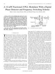
1516 <strong>IEEE</strong> TRANSACTIONS ON CIRCUITS AND SYSTEMS—I: REGULAR PAPERS, VOL. 58, NO. 7, JULY 2011 TABLE I PERFORMANCE SUMMARY The precision varies over the range. The range is 11 bits for a precision less than 1 LSB. Fig. 17. Application of TDC in ADPLL. Fig. 15. edge. Measurement time reduction by detecting either of rising or falling The measured DNL and INL are less than 1 LSB when the phase error is lower than a half cycle of OSC . Though the inaccuracy of the duty cycle affects the prelock operation of the ADPLL, it is not critical for the purpose of the ADPLL when locked. In the ADPLL application, a target offset value can be subtracted from the TDC output before it is filtered by the DLF as shown in Fig. 17. This way, the ADPLL is locked around the target offset, thereby avoiding any mismatch problem in Fig. 16, and reducing power consumption which is proportional to the measured time difference. Fig. 16. Calculated output versus input time difference. In this figure, the offset from input signal paths such as cable and PCB is adjusted. The measured duty cycle is 41%, and the deviation by duty cycle variation is observed. the calculated TDC output from the coarse output code and fine output code. As can be seen in this figure, the calculated output from falling edge detection deviates from the desired values, if the duty cycle varies. Fig. 16 also shows inaccuracy around multiple cycles of OSC due to coarse/fine code ratio mismatch. The application of the proposed TDC; however, is a phase detector in ADPLLs for clock synthesis. If the PLL is programmed to be locked at a lower phase error, the phase error greater than a half cycle of OSC is used to steer the ADPLL dynamics closer to lock, and ultimately the performance is dependent only on the lower phase error measurements when the ADPLL is locked. C. Power The power dissipation in the Vernier structure depends on , and the sampling frequency of the TDC. The DCOs, which are the most power hungry blocks in the TDC, oscillate only when is measured. Therefore, the TDC operation is duty-cycled, and power dissipation is proportional to the sampling frequency. During the coarse step operation, only the slow DCO oscillates, and the measurement time is the same as the without any latency. During the fine step operation; however, both DCOs are oscillating, and the measurement time is inversely proportional to the fine step resolution, and multiplied by . The measured power consumption during coarse and fine step measurements is as follows: (4) (5)
PARK AND WENTZLOFF: A CYCLIC VERNIER TDC FOR ADPLLs SYNTHESIZED FROM A STANDARD CELL LIBRARY 1517 where and is power during coarse and fine step measurements, and is sampling frequency of the TDC. V. CONCLUSION An all-digital synthesizable cyclic Vernier TDC was proposed and designed in a 65 nm CMOS process. While there has been increasing interest in all-digital implementations of conventional analog functions, the proposed TDC shows a new design methodology, where all functional blocks are implemented with standard cells, and automatically P&R-ed. The systematic mismatch by P&R is also addressed, and further exploited to obtain higher performance. The TDC can be a building block for a synthesizable ADPLL as a clock synthesizer, leveraging the automated design tools and standard cell engineering. REFERENCES [1] B. Murmann, “Digitally-assisted analog circuits,” <strong>IEEE</strong> Micro, vol. 26, no. 2, pp. 38–47, Mar.–Apr. 2006. [2] B. Murmann, “A/D converter trends: Power dissipation, scaling and digitally assisted architecture,” in Proc. <strong>IEEE</strong> Custom Integr. Circuit Conf., Sep. 2008, pp. 105–112. [3] M. Lee, M. E. Heidari, and A. A. Abidi, “A low noise, wideband digital phase-locked loop based on n tew Time-to-digital converter with subpicosecond resolution,” in Proc. <strong>IEEE</strong> VLSI Symp. Dig. Tech. Papers, Jun. 2008, pp. 112–113. [4] M. S.-W. Chen, D. Su, and S. Mehta, “A calibration-free 800 MHz fractional-N digital PLL with embedded TDC,” in ISSCC Dig. Tech. Papers, Feb. 2010, pp. 472–473. [5] R. B. Staszewski, C.-M. Hung, N. Barton, M.-C. Lee, and D. Leipold, “A digitally controlled oscillator in a 90 nm digital CMOS process for mobile phones,” <strong>IEEE</strong> J. Solid-State Circuits, vol. 40, no. 11, pp. 2203–2211, Nov. 2005. [6] P. Chen, C. C. Chen, J. C. Zheng, and Y. S. Shen, “A PVT insensitive vernier-based time-to-digital converter with extended input range and high accuracy,” <strong>IEEE</strong> Trans. Nuclear Sci., vol. 54, pp. 294–302, Apr. 2007. [7] J. Yu, F. F. Dai, and R. C. Jaeger, “A 12-bit vernier ring time-to-digital converter in 0.13 m CMOS technology,” <strong>IEEE</strong> J. Solid-State Circuits, vol. 45, no. 4, pp. 830–842, Apr. 2010. [8] M. Lee and A. A. Abidi, “A 9 b, 1.25 ps resolution coarse-fine time-todigital converter in 90 nm CMOS that amplifies a time residue,” <strong>IEEE</strong> J. Solid-State Circuits, vol. 43, no. 4, pp. 769–777, Apr. 2008. [9] M. Z. Straayer and M. H. Perrott, “A multi-path gated ring oscillator TDC with first-order noise shaping,” <strong>IEEE</strong> J. Solid-State Circuits, vol. 44, no. 4, pp. 1089–1098, Apr. 2009. [10] S. Henzler, S. Koeppe, W. Kamp, H. Mulatz, and D. Schmitt-Landsiedel, “90 nm 4.7 ps-resolution 0.7-LSB single-shot precision and 19 pJ-per shot local passive interpolation time-to-digital converter with on-cihp characterization,” in <strong>IEEE</strong> Int. Solid-State Circuits Conf. Dig. Tech. Papers, Feb. 2008, pp. 548–549. [11] L. Vercesi, A. Liscidini, and R. Castello, “Two-dimensions vernier time-to-digital converter,” <strong>IEEE</strong> J. Solid-State Circuits, vol. 45, no. 8, pp. 1504–1512, Aug. 2010. [12] A. Mantyniemi, T. Rahkonen, and J. Kostamovaara, “A CMOS time-to-digital converter (TDC) based on a cyclic time domain successive approximation interpolation method,” <strong>IEEE</strong> J. Solid-State Circuits, vol. 44, no. 11, pp. 3067–3077, Nov. 2009. [13] M. Zanuso, P. Madoglio, S. Levantino, C. Samori, and A. L. Lacaita, “Time-to-digital converter for frequency synthesis based on a digital bang-bang DLL,” <strong>IEEE</strong> Trans. Circuits Syst. I, Reg. Papers, vol. 57, no. 3, pp. 548–554, Mar. 2010. [14] J.-P. Jansson, A. Mantyniemi, and J. Kostamovaara, “Synchronization in a multi-level CMOS time-to-digital converter,” <strong>IEEE</strong> Trans. Circuits Syst. I, Reg. Papers, vol. 56, no. 8, pp. 1622–1634, Aug. 2009. [15] T. Tokairin, M. Okada, M. Kitsunezuka, T. Maeda, and M. Fukaishi, “A 2.1-to-2.8-GHz low-phase-noise all-digital frequency synthesizer with a time-windowed time-to-digital converter,” <strong>IEEE</strong> J. Solid-State Circuits, vol. 45, no. 12, pp. 2582–2590, Dec. 2010. [16] Y.-H. Seo, S.-K. Lee, and J.-Y. Sim, “A 1-GHz digital PLL with a 3-ps resolution floating-point-number TDC in a 0.18- m CMOS,” <strong>IEEE</strong> Trans. Circuits Syst. II, Exp. Briefs, vol. 58, no. 2, pp. 70–74, Feb. 2011. [17] Y. Park and D. D. Wentzloff, “A cyclic vernier time-to-digital converter synthesized from a 65 nm CMOS standard library,” in <strong>IEEE</strong> Proc. Int. Symp. Circuits Syst., Jun 2010, pp. 3561–3564. [18] Y. Park and D. D. Wentzloff, “An all-digital 12 pJ/pulse IR-UWB transmitter synthesized from a standard cell library,” <strong>IEEE</strong> J. Solid-State Circuits, vol. 46, no. 5, pp. 1147–1157, May. 2011. Youngmin Park (S’07) received the B.S. degree in electrical engineering from the Seoul National University, Seoul, Korea, in 2005, and the M.S. degree in electrical engineering from the University of Michigan, Ann Arbor, in 2007, where he is currently working towards the Ph.D. degree. In Summer 2007, he held an internship position with the Memory Division at Samsung Electronics, Hwasung, Korea. He is the recipient of the Kwanjeong Educational Foundation fellowship. David D. Wentzloff (M’02) received the B.S.E. degree in electrical engineering from the University of Michigan, Ann Arbor, in 1999, and the S.M. and Ph.D. degrees from the Massachusetts Institute of Technology, Cambridge, in 2002 and 2007, respectively. In Summer 2004, he worked in the Portland Technology Development group at Intel, Hillsboro, OR. Since August 2007, he has been with the University of Michigan, Ann Arbor, where he is currently an Assistant Professor of Electrical Engineering and Computer Science. Prof. Wentzloff is the recipient of the 2002 MIT Masterworks Award, 2004 Analog Devices Distinguished Scholar Award, 2009 DARPA Young Faculty Award, the 2009–2010 Eta Kappa Nu Professor of the Year Award, and the 2011 DAC/ISSCC Student Design Contest Award. He is a member of <strong>IEEE</strong> Circuits and Systems Society, <strong>IEEE</strong> Microwave Theory and Techniques Society, <strong>IEEE</strong> Solid-State Circuits Society, and Tau Beta Pi. He has served on the technical program committee for ICUWB 2008–2010 and ISLPED 2011, and as a guest editor for the <strong>IEEE</strong> TRANSACTIONS ON MICROWAVE THEORY AND TECHNIQUES, the <strong>IEEE</strong> Communications Magazine, and the Elsevier Journal of Signal Processing: Image Communication.


![[Sample B: Approval/Signature Sheet]](https://img.yumpu.com/34084789/1/190x245/sample-b-approval-signature-sheet.jpg?quality=85)