ECP300 Expert Use and maintenance manual - Cool Italia GmbH
ECP300 Expert Use and maintenance manual - Cool Italia GmbH
ECP300 Expert Use and maintenance manual - Cool Italia GmbH

You also want an ePaper? Increase the reach of your titles
YUMPU automatically turns print PDFs into web optimized ePapers that Google loves.
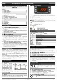
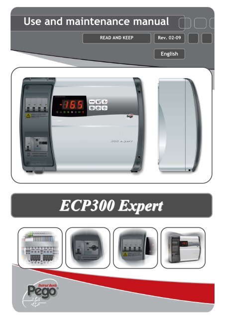
<strong>Use</strong> <strong>and</strong> <strong>maintenance</strong> <strong>manual</strong><br />
READ AND KEEP<br />
Rev. 02-09<br />
English<br />
<strong>ECP300</strong> <strong>Expert</strong>
<strong>ECP300</strong> EXPERT<br />
Thanks for choosing this PEGO electrical panel.<br />
This <strong>manual</strong> gives detailed information on installation, use <strong>and</strong> <strong>maintenance</strong> of <strong>ECP300</strong><br />
EXPERT series electrical panels <strong>and</strong> special version. Our products are designed <strong>and</strong> built<br />
in compliance with current st<strong>and</strong>ards, on the specific field of refrigeration <strong>and</strong> conditioning<br />
systems. A different use is allowed respecting the working conditions for which the panel is<br />
designed <strong>and</strong> made.<br />
Before using the panel it’s suggested to fully read this <strong>manual</strong> paying special attention to<br />
the highlighted parts with the simbology descripted below:<br />
This symbol is used to focus on notes concerning installation, use <strong>and</strong><br />
<strong>maintenance</strong> operations<br />
This symbol is used to focus on important notes<br />
This symbol is used to indicate the prohibition to do the shown operation
Index<br />
<strong>ECP300</strong> EXPERT<br />
CONTENTS<br />
INTRODUCTION<br />
Pag. 4 1.1 General<br />
TECHNICAL CHARACTERISTICS<br />
Pag. 5 2.1 Product ID codes<br />
Pag. 6 2.2 Product series - Technical characteristics<br />
Pag. 8 2.3 Overall dimensions<br />
Pag. 9 2.4 Identification data<br />
Pag. 10 2.5 Transport <strong>and</strong> storage<br />
Pag. 11 2.6 Warranty<br />
INSTALLATION<br />
Pag. 12 3.1 St<strong>and</strong>ard assembly kit<br />
Pag. 12 3.2 Mechanical assembly<br />
Pag. 17 3.3 Electrical wirings<br />
Pag. 18 3.4 Front panel connections<br />
Pag. 19 3.5 Verifications before use<br />
Pag. 20 3.6 Compressor motor circuit breaker calibration<br />
Pag. 21 3.7 Electrical panel closing<br />
FUNCTIONS<br />
Pag. 22 4.1 <strong>ECP300</strong> <strong>Expert</strong> panel functions<br />
DATA PROGRAMMING<br />
Pag. 23 5.1 Control panel<br />
Pag. 23 5.2 Front keypad<br />
Pag. 24 5.3 LED Display<br />
Pag. 25 5.4 General<br />
Pag. 25 5.5 Key to symbols<br />
Pag. 25 5.6 Setting <strong>and</strong> displaying the set points<br />
Pag. 26 5.7 Level 1 programming. (<strong>Use</strong>r Level)<br />
Pag: 27 5.8 List of Level 1 variables<br />
Pag. 27 5.9 Level 2 programming. (Installer Level)<br />
Pag. 29 5.10 List of Level 2 variables<br />
Pag. 30 5.11 Switching on the <strong>ECP300</strong> <strong>Expert</strong> electrical panel<br />
Pag. 30 5.12 Compressor activation/deactivation conditions<br />
Pag. 30 5.13 Manual defrosting<br />
Pag. 31 5.14 Pump-Down function<br />
Pag. 32 5.15 Password protection<br />
OPTIONAL KIT<br />
Pag. 32 6.1 TeleNET monitoring / supervision system<br />
Pag. 32 6.2 Net configuration with Modbus-rtu protocol<br />
Pag. 33 6.3 Alarm/AUX relay / TeleNET switching<br />
TROUBLESHOOTING<br />
Pag. 38 7.1 Alarm codes<br />
Pag. 39 7.2 Troubleshooting<br />
MAINTENANCE<br />
Pag. 38 8.1 General security rules<br />
Pag. 39 8.2 Maintenance<br />
Pag. 39 8.3 Spare parts<br />
ALLEGATI / APPENDICES<br />
Pag. 40 A.1 EC declaration of conformity<br />
Pag. 41 A.2 TeleNET network connection diagram<br />
Pag. 42 A.3 Part list<br />
CHAP. 1<br />
CHAP. 2<br />
CHAP. 3<br />
CHAP. 4<br />
CHAP. 5<br />
CHAP. 6<br />
CHAP. 7<br />
CHAP. 8<br />
Rev. 02-09<br />
USE AND MAINTENANCE MANUAL<br />
Pag. 3
<strong>ECP300</strong> EXPERT<br />
CHAP. 1 - Introduction<br />
CHAPTER 1: INTRODUCTION<br />
1.1<br />
GENERAL<br />
DESCRIPTION:<br />
A line of power <strong>and</strong> control panels for refrigeration systems with three-phase compressor or<br />
to control only the three-phase evaporating unit, for the complete management of the room.<br />
Magnetothermic protection <strong>and</strong> motor circuit breaker for the compressor accessible from the<br />
front panel linked to an innovative form makes it a perfect <strong>and</strong> functional choice.<br />
<strong>ECP300</strong> <strong>Expert</strong> VD<br />
A line of power <strong>and</strong> control panels for refrigeration plants with three-phase compressor up to<br />
7.5 HP, for the complete management of the room.<br />
Different range of power combined with the various options allow the choice of an “AD HOC”<br />
panel for the system.<br />
APPLICATIONS:<br />
- Complete management of three-phase refrigerating systems up to 7,5 HP static or<br />
ventilated, with off-cycle or electrical defrosting.<br />
<strong>ECP300</strong> <strong>Expert</strong> U VD<br />
A line of power <strong>and</strong> control panels for refrigeration systems to control only the three-phase<br />
evaporating unit where units are served by a central refrigerator or remote condenser unit.<br />
Different range of power combined with the various options allow the choice of an “AD HOC”<br />
panel for the system.<br />
APPLICATIONS:<br />
- Control of evaporating unit with electrical defrost up to 12 kW.<br />
- Remote control for compressor enable to be linked with a power panel.<br />
Pag. 4 USE AND MAINTENANCE MANUAL Rev. 02-09
CHAP. 2 - Technical characteristics<br />
<strong>ECP300</strong> EXPERT<br />
CHAPTER 2: TECHNICAL CHARACTERISTICS<br />
(*) Code available on request<br />
PRODUCT ID CODES<br />
2.1<br />
Panels line <strong>ECP300</strong> <strong>Expert</strong> VD 4 series<br />
Siemens components<br />
PEGO identification codes Compressor motor<br />
circuit breaker range<br />
110300EVD401 (*)<br />
1,1-1,6A<br />
110300EVD402<br />
1,4-2A<br />
110300EVD403<br />
1,8-2,5A<br />
110300EVD404<br />
2,2-3,2A<br />
110300EVD405<br />
2,8-4A<br />
110300EVD406<br />
3,5-5A<br />
110300EVD407<br />
4,5-6,3A<br />
110300EVD408<br />
5,5-8A<br />
110300EVD409 7-10A<br />
110300EVD410 (*) 9-12A<br />
Telemecanique components<br />
PEGO identification codes<br />
Compressor motor<br />
circuit breaker range<br />
110300EVD421 (*)<br />
1-1,6A<br />
110300EVD422<br />
1,6-2,5A<br />
110300EVD423<br />
2,5-4A<br />
110300EVD424<br />
4-6,3A<br />
110300EVD425 6-10A<br />
Panels line <strong>ECP300</strong> <strong>Expert</strong> VD 7 series<br />
Siemens components<br />
Compressor motor<br />
PEGO identification codes<br />
circuit breaker range<br />
110300EVD701 (*)<br />
5,5-8A<br />
110300EVD702 (*) 7-10A<br />
110300EVD703<br />
9-12,5A<br />
110300EVD704 11-16A<br />
110300EVD705 14-20A<br />
Telemecanique components<br />
Compressor motor<br />
PEGO identification codes<br />
circuit breaker range<br />
110300EVD721 (*) 6-10A<br />
110300EVD722 9-14A<br />
110300EVD723 13-18A<br />
Panels line <strong>ECP300</strong> <strong>Expert</strong> U VD series<br />
Siemens components<br />
Heaters electrical<br />
PEGO identification codes<br />
defrost<br />
110300EUVD01<br />
6kW<br />
110300EUVD02<br />
12kW<br />
Telemecanique components<br />
PEGO identification codes<br />
Heaters electrical<br />
defrost<br />
110300EUVD21<br />
6kW<br />
110300EUVD22<br />
12kW<br />
Rev. 02-09<br />
USE AND MAINTENANCE MANUAL<br />
Pag. 5
<strong>ECP300</strong> EXPERT<br />
CAP. 2 - Caratteristiche tecniche<br />
2.2<br />
PRODUCT SERIES – TECHNICAL CHARACTERISTICS<br />
Technical characteristics <strong>ECP300</strong> <strong>Expert</strong> VD 4 <strong>ECP300</strong> <strong>Expert</strong> VD 7<br />
Box dimensions 400x300x135 mm 400x300x135 mm<br />
Weight 9 Kg 10 Kg<br />
Protection rating IP65 IP65<br />
Power supply (3F+N+T) 400Vac ±10% 50/60Hz 400Vac ±10% 50/60Hz<br />
Load type 3-phase 3-phase<br />
Working temperature - 5 ÷ + 40 °C - 5 ÷ + 40 °C<br />
Storage temperature -25 ÷ +55 °C -25 ÷ +55 °C<br />
Relative ambient humidity From 30% to 95% RH w/out condensate From 30% to 95% RH w/out condensate<br />
Altitude < 1.000 m < 1.000 m<br />
Main switch / general protection<br />
Interruption power<br />
4 poles magnetothermic 16A “D”<br />
Icn=6kA / Ics=8kA / Icu=15kA<br />
4 poles magnetothermic 25A “D”<br />
Icn=6kA / Ics=8kA / Icu=15kA<br />
Compressor protection Adjustable motor circuit breaker Adjustable motor circuit breaker<br />
Control PEGO PEGO<br />
Defrosting Electrical Electrical<br />
Status indicators LED + display LED + display<br />
Alarm signals LED + Buzzer LED + Buzzer<br />
Inputs<br />
Ambient probe NTC 10K 1% NTC 10K 1%<br />
Evaporator probe NTC 10K 1% NTC 10K 1%<br />
Door switch Present Present<br />
High/low pressure switch Present Present<br />
Kriwan ® connection Present Present<br />
Compressor functioning mode selection Pump-down / Thermostat Pump-down / Thermostat<br />
Outputs<br />
Compressor<br />
See motor circuit breaker thermal range<br />
relative to PEGO panel ID code<br />
See motor circuit breaker thermal range<br />
relative to PEGO panel ID code<br />
Condenser fans output 1 800W (1ph) 800W (1ph)<br />
Condenser fans output 2 (separated) total (1ph)<br />
Evaporator fans 500W (1ph) 2000W (1ph / 3ph)<br />
Defrosting heaters 6000W (AC1) eq. resistive load 9000W (AC1) eq. resistive load<br />
Room light 800W (AC1) resistive load 800W (AC1) resistive load<br />
Solenoid valve Present Present<br />
Compressor oil heater Present Present<br />
Alarm relay 100W 100W<br />
Supervision system TeleNET TeleNET<br />
Connection diagrams :<br />
Pag. 6 USE AND MAINTENANCE MANUAL Rev. 02-09
CHAP. 2 - Technical characteristics<br />
<strong>ECP300</strong> EXPERT<br />
Technical characteristics <strong>ECP300</strong> <strong>Expert</strong> U VD 6 <strong>ECP300</strong> <strong>Expert</strong> U VD 12<br />
Box dimensions 400x300x135 mm 400x300x135 mm<br />
Weight 9 Kg 10 Kg<br />
Protection rating IP65 IP65<br />
Power supply (3F+N+T) 400Vac ±10% 50/60Hz 400Vac ±10% 50/60Hz<br />
Load type 3-phase 3-phase<br />
Working temperature - 5 ÷ + 40 °C - 5 ÷ + 40 °C<br />
Storage temperature -25 ÷ +55 °C -25 ÷ +55 °C<br />
Relative ambient humidity From 30% to 95% RH w/out condensate From 30% to 95% RH w/out condensate<br />
Main switch / general protection<br />
Interruption power<br />
4 poles magnetothermic 16A “D”<br />
Icn=6kA / Ics=8kA / Icu=15kA<br />
4 poles magnetothermic 25A “D”<br />
Icn=6kA / Ics=8kA / Icu=15kA<br />
Room light protection<br />
Differential magnetothermic circuit breaker<br />
Id=30mA<br />
Differential magnetothermic circuit breaker<br />
Id=30mA<br />
Control PEGO PEGO<br />
Defrosting Electrical Electrical<br />
Status indicators LED + display LED + display<br />
Alarm signals LED + Buzzer LED + Buzzer<br />
Inputs<br />
Ambient probe NTC 10K 1% NTC 10K 1%<br />
Evaporator probe NTC 10K 1% NTC 10K 1%<br />
Door switch Present Present<br />
Man in cold-room alarm Available Available<br />
Outputs<br />
Evaporator fans 500W (1ph) 2000W (1ph / 3ph)<br />
Defrosting heaters 6000W (AC1) eq. resistive load 12000W (AC1) eq. resistive load<br />
Room light 800W (AC1) resistive load 1200W (AC1) resistive load<br />
Solenoid valve Present Present<br />
Enable condensing unit Present Present<br />
Configurable alarm relay (AUX / alarm) 100W 100W<br />
Door heater Present Present<br />
Supervision system TeleNET TeleNET<br />
Connection diagrams :<br />
Rev. 02-09<br />
USE AND MAINTENANCE MANUAL<br />
Pag. 7
<strong>ECP300</strong> EXPERT<br />
CHAP. 2 - Technical characteristics<br />
2.3<br />
OVERALL DIMENSIONS<br />
Pag. 8 USE AND MAINTENANCE MANUAL Rev. 02-09
CHAP. 2 - Technical characteristics<br />
<strong>ECP300</strong> EXPERT<br />
IDENTIFICATION DATA<br />
2.4<br />
The product descripted in this <strong>manual</strong> is provided on the side with a label where its<br />
identification data are written :<br />
• Name of Manufacturer<br />
• Code <strong>and</strong> model of unit electrical board<br />
• Serial number (S/N)<br />
• Power supply<br />
• Auxiliary circuits power supply<br />
• IP protection rating<br />
Rev. 02-09<br />
USE AND MAINTENANCE MANUAL<br />
Pag. 9
<strong>ECP300</strong> EXPERT<br />
CHAP. 2 - Technical characteristics<br />
2.5<br />
TRANSPORT AND STORAGE<br />
Every panel is packed to be delivered without damages in normal transport conditions. In case<br />
of following transport it must be verified that :<br />
<br />
<br />
<br />
No objects or free parts could be inside the panel.<br />
The door is correctly closed <strong>and</strong> locked.<br />
In case of not using the original package, protect the product to<br />
allow transport without any damages.<br />
Storage room must have an adeguate temperature <strong>and</strong> low humidity value; then avoid contact<br />
between the electrical panel <strong>and</strong> aggressive contaminating substances that could prejudice<br />
functionality <strong>and</strong> electrical security.<br />
Pag. 10 USE AND MAINTENANCE MANUAL Rev. 02-09
CHAP. 2 - Technical characteristics<br />
<strong>ECP300</strong> EXPERT<br />
WARRANTY<br />
2.6<br />
<br />
<br />
<br />
<br />
<br />
<br />
<br />
<br />
<br />
<br />
<br />
<br />
<strong>ECP300</strong> EXPERT panel series are covered by 24-months warranty from delivery<br />
date against all manufacturing defects.<br />
In case of defect, the product will be sent with appropriate package to our factory or<br />
any authorized Service center.<br />
Customer has granted the repair of detective product with spare parts <strong>and</strong> labour<br />
included. The expenses <strong>and</strong> transport risk are totally at Customer charge.<br />
Every warranty intervention does not prolong nor renews warranty expiration date.<br />
Warranty excluded for:<br />
o Damages result of tampering, impact or improper installation.<br />
o Behaviour not in compliance with Manufacturer prescriptions <strong>and</strong> instructions.<br />
o Repair intervention made by unauthorized people.<br />
In all these cases repair cost will be totally at Customer charge.<br />
Warranty intervention service may be refused if the device results modified or<br />
changed.<br />
The Manufacturer declines every responsibility for any direct or indirect damages to<br />
animal, people or things in consequence of missing observance of all the<br />
prescriptions shown in the user <strong>manual</strong>, specially instructions regarding installation,<br />
use <strong>and</strong> <strong>maintenance</strong> of the device.<br />
For all not expressely indicated, usual law rules are applied <strong>and</strong> in particular<br />
art.1512 C.C.<br />
For every controversy we mean elected <strong>and</strong> recognized by the parts the<br />
competence of “Foro di Rovigo”.<br />
PEGO S.r.l. cannot be held liable for possible errors or inaccuracies written in this<br />
<strong>manual</strong> as a result of printing or transcription errors<br />
PEGO S.r.l. reserves the right to modify its products as it deems necessary without<br />
altering its main characteristics.<br />
Each new release of a PEGO user <strong>manual</strong> replaces previous ones.<br />
Rev. 02-09<br />
USE AND MAINTENANCE MANUAL<br />
Pag. 11
<strong>ECP300</strong> EXPERT<br />
CHAP. 3 - Installation<br />
CHAPTER 3: INSTALLATION<br />
3.1<br />
STANDARD ASSEMBLY KIT<br />
For the purposes of assembly <strong>and</strong> use, the electronic <strong>ECP300</strong> EXPERT control unit comes<br />
with:<br />
• N° 4 seals, to be fitted between the fixing screws <strong>and</strong> the box back panel<br />
• N° 1 use <strong>and</strong> <strong>maintenance</strong> <strong>manual</strong>.<br />
• N° 1 electrical drawing.<br />
• N° 1 drilling layout.<br />
• N° 2 probes NTC 10K 1%<br />
3.2<br />
MECHANICAL ASSEMBLY<br />
<br />
<br />
<br />
<br />
<br />
Each panel is conceived to be wall-mounted; please choose depending on the<br />
weight a correct fixing method.<br />
Install the device in places where the protection rating is observed.<br />
To effect correct electrical connection <strong>and</strong> maintain the protection rating, use<br />
appropriate cable gl<strong>and</strong>s <strong>and</strong> plugs to ensure a good seal<br />
Install the device at height allowing the installer an easier use <strong>and</strong> <strong>maintenance</strong>.<br />
The installer must not be in danger when it’s working on the panel. Height must<br />
be between 0,6 <strong>and</strong> 1,7 mt from the ground.<br />
Install the device away from fire <strong>and</strong> heat sources <strong>and</strong> possibly repaired from<br />
weather shelter.<br />
Below we show step by step how to correctly install the panel.<br />
Pag. 12 USE AND MAINTENANCE MANUAL Rev. 02-09
CHAP. 3 - Installation<br />
<strong>ECP300</strong> EXPERT<br />
Fig. 1:<br />
Pull up transparent cover protecting<br />
the general magnetothermic circuit<br />
breaker.<br />
Fig. 2:<br />
Remove screw cover on the right-h<strong>and</strong><br />
side.<br />
Fig. 3:<br />
Undo the 4 fixing screws at the front of<br />
the box.<br />
Rev. 02-09<br />
USE AND MAINTENANCE MANUAL<br />
Pag. 13
<strong>ECP300</strong> EXPERT<br />
CHAP. 3 - Installation<br />
Fig. 4:<br />
Close the transparent protection cover.<br />
Fig. 5:<br />
.<br />
Open the front of the box, lift it <strong>and</strong><br />
slide the two hinges out as far as they<br />
will go.<br />
Fig. 6:<br />
Bend the hinges <strong>and</strong> rotate the front<br />
panel by 180° downward to get access<br />
inside the panel; then disconnect the<br />
connector to electronic card.<br />
Pag. 14 USE AND MAINTENANCE MANUAL Rev. 02-09
CHAP. 3 - Installation<br />
<strong>ECP300</strong> EXPERT<br />
Fig. 7:<br />
Press on the sides of the hinges to<br />
remove them from their seats <strong>and</strong> so<br />
completely remove the front panel<br />
Fig. 8: Press with a screwdriver on the 4<br />
preimpressed holes on the bottom to<br />
prepare fixing of the panel.<br />
.<br />
Fig. 9:<br />
Using the furnished drilling layout make<br />
four fixing holes on the wall.<br />
Rev. 02-09<br />
USE AND MAINTENANCE MANUAL<br />
Pag. 15
<strong>ECP300</strong> EXPERT<br />
CHAP. 3 - Installation<br />
Fig.10: Using holes made on previous point fix<br />
the bottom with 4 screws of a length<br />
suitable for the thickness of the wall to<br />
which the panel will be attached. Fit a<br />
o-ring (supplied) between each screw<br />
<strong>and</strong> the box backing.<br />
.<br />
Fig.11: Now make the electrical wirings as<br />
indicated in the next chapter<br />
.<br />
Pag. 16 USE AND MAINTENANCE MANUAL Rev. 02-09
CHAP. 3 - Installation<br />
<strong>ECP300</strong> EXPERT<br />
ELECTRICAL WIRINGS<br />
3.3<br />
<br />
For the electrical wirings please refer to the wiring diagram <strong>and</strong> technical<br />
characteristics of the panel model to be installed.<br />
<br />
Panel power supply must be on a dedicated line, <strong>and</strong> must be placed a<br />
device suitable for protection against indirect contacts upstream the line<br />
(differential interruptor).<br />
<br />
Do not fit power supply wiring <strong>and</strong> signal wiring (probes/sensors <strong>and</strong><br />
digital inputs) in the same raceways or ducts.<br />
<br />
Do not use multi-polar cables in which there are wires connected to<br />
inductive/power loads or signalling wires (e.g. probes/sensors <strong>and</strong> digital<br />
inputs).<br />
<br />
Minimise the length of connector wires so that wiring does not twist into a<br />
spiral shape as this could have negative effects on the electronics.<br />
<br />
When it is necessary to make a probe/sensor extension, the wires must<br />
have a cross-section of at least 1 mm 2 .<br />
<br />
All wiring must be of a cross-section suitable for relevant power levels.<br />
Insulation degree must be compatible with the applied voltages.<br />
Preferably use cables with insulator not propagating the flame <strong>and</strong> a low<br />
toxic smoke emission if interested by fire.<br />
<br />
It is obligatory to connect clamp marked with PE abbreviation to the<br />
ground of the supply system. If necessary, please verify ground system<br />
efficiency.<br />
<br />
Do not connect to the PE clamp conductors different from the external<br />
protection one.<br />
Rev. 02-09<br />
USE AND MAINTENANCE MANUAL<br />
Pag. 17
<strong>ECP300</strong> EXPERT<br />
CHAP. 3 - Installation<br />
3.4<br />
FRONT PANEL CONNECTION<br />
Hook front panel <strong>and</strong> reconnect the electronic card connector as indicated below.<br />
Fig.12: Hook the frontal panel back up to the<br />
lower part of the box by inserting the<br />
two hinges in their seats.<br />
Fig.13: Bend the hinges <strong>and</strong> rotate the front<br />
panel downwards 180° to gain access<br />
inside the panel <strong>and</strong> then reconnect<br />
the electronic card connector.<br />
.<br />
Fig.13: In case panel is connected with<br />
TeleNET or Alarm/Aux relay is used<br />
wirings must be done directly on the<br />
electronic card clamps.<br />
It’s suggested to put that wirings<br />
beside the connection cables from<br />
electronic card <strong>and</strong> bottom of the box.<br />
For further clarification on the clamps<br />
please refer to the chapter “TeleNET<br />
SUPERVISING AND MONITORING<br />
SYSTEM”.<br />
Pag. 18 USE AND MAINTENANCE MANUAL Rev. 02-09
CHAP. 3 - Installation<br />
<strong>ECP300</strong> EXPERT<br />
VERIFICATIONS BEFORE USE<br />
3.5<br />
<br />
After doing the wirings, please verify using the wiring diagram on the<br />
correct execution of the connections.<br />
<br />
Please check the correct screw clamping.<br />
<br />
Check, when possible, the correct functioning of the outside protection<br />
devices.<br />
<br />
Please correctly calibrate the motor circuit breaker (if present) dedicated<br />
to the compressor as indicated in the next chapter.<br />
<br />
After powering the electrical panel please check the correct current<br />
absorption on the loads, <strong>and</strong> after few hours of functioning check the<br />
good tightening of screws on terminal blocks (included power supply line<br />
connection). Warning: before doing that it’s necessary to cut off power<br />
sectioning power supply upstream the line <strong>and</strong> block it with a padlock for<br />
max. safety. Before any operation verify with a tester the absence of<br />
voltage.<br />
Rev. 02-09<br />
USE AND MAINTENANCE MANUAL<br />
Pag. 19
<strong>ECP300</strong> EXPERT<br />
CHAP. 3 - Installation<br />
3.6<br />
COMPRESSOR MOTOR CIRCUIT BREAKER CALIBRATION<br />
Below we show step by step how to correctly calibrate motor circuit breaker dedicated to the<br />
compressor.<br />
Fig.12: When the system is started for first<br />
time it’s suggested to calibrate the<br />
motor circuit breaker on the<br />
compressor power circuits. Using an<br />
ammeter verify the effective<br />
absorption.<br />
.<br />
Fig.13: Make the motor circuit breaker<br />
calibration basing on the measured<br />
absorption. Any way the set up value<br />
must not be higher than the one<br />
expected by the compressor<br />
manufacturer. Warning: a wrong<br />
calibration may cause compressor<br />
breakdown or bad intervention of the<br />
motor circuit breaker.<br />
Fig.14: To make the calibration use the<br />
regulation screw on the front side of<br />
motor circuit breaker.<br />
.<br />
Pag. 20 USE AND MAINTENANCE MANUAL Rev. 02-09
CHAP. 3 - Installation<br />
<strong>ECP300</strong> EXPERT<br />
ELECTRICAL PANEL CLOSING<br />
3.7<br />
When electrical wirings, verifications <strong>and</strong> calibrations are finished continue with the panel<br />
closing.<br />
Fig.15: Close the front panel, making sure that<br />
all the wires are inside the box <strong>and</strong> that<br />
the box seal sits in its seat properly<br />
Fig.16: Tighten the front panel using the 4<br />
screws, making sure the O-rings on the<br />
head of each screw are used. Reposition<br />
screw cover on the right-h<strong>and</strong> side.<br />
.<br />
Fig.17: Power up the panel <strong>and</strong> carry out<br />
thorough reading/programming of all the<br />
parameters.<br />
.<br />
Rev. 02-09<br />
USE AND MAINTENANCE MANUAL<br />
Pag. 21
<strong>ECP300</strong> EXPERT<br />
CHAP. 4 - Functions<br />
CHAPTER 4: FUNCTIONS<br />
4.1<br />
<strong>ECP300</strong> EXPERT PANEL FUNCTIONS<br />
- Signaling with LED icons of the plant status.<br />
- Electronic control with wide LED display <strong>and</strong> easy to use buttons.<br />
- Display <strong>and</strong> adjustment of cold room temperature accurate to 0.1 °C.<br />
- Display of evaporator temperature from parameter.<br />
- System control activation/deactivation.<br />
- Alarm signaling: probe errors, minimum <strong>and</strong> maximum temperature alarm, compressor<br />
protection (man in cold room alarm in preset models).<br />
- Evaporator fans control.<br />
- Automatic <strong>and</strong> <strong>manual</strong> defrost control (static, heating element).<br />
- Direct or pump-down control of motor compressor unit (selectable by terminal block<br />
connection in preset models).<br />
- Room light activation, via panel key or door switch<br />
- Auxiliary relay with activation configurable by parameter.<br />
- RS485 for connection to TeleNET industrial supervision network.<br />
- Paramet access with Password (4 different selectable restriction levels).<br />
- General magnetothermic circuit breaker accessible from the front panel, which cuts the<br />
general power supply.<br />
- Adjustable motor circuit breaker for compressor protection accessible from the front panel<br />
(in preset models).<br />
- Differential magnetothermic Id=30mA dedicated to room light accessible from the front<br />
panel (in preset models).<br />
Pag. 22 USE AND MAINTENANCE MANUAL Rev. 02-09
CHAP. 5 - Data programming<br />
<strong>ECP300</strong> EXPERT<br />
CHAPTER 5: DATA PROGRAMMING<br />
CONTROL PANEL<br />
5.1<br />
FRONT KEYPAD<br />
<br />
5.2<br />
<br />
<br />
<br />
1. key: AUXILIARY RELAY CONTROL (on the version with alarm relay <strong>manual</strong>ly<br />
controls the relay if parameter AU=1)<br />
2. key: UP / MUTE WARNING BUZZER<br />
3. key: STAND BY (if the system shuts down the LED flashes)<br />
4. key: room temperature SETTING<br />
5. key: DOWN / MANUAL DEFROST<br />
6. key: ROOM LIGHT<br />
Rev. 02-09<br />
USE AND MAINTENANCE MANUAL<br />
Pag. 23
<strong>ECP300</strong> EXPERT<br />
CHAP. 5 - Data programming<br />
5.3<br />
LED DISPLAY<br />
<br />
<br />
1. Cold room temperature / parameters<br />
2. St<strong>and</strong>-by (flashes on st<strong>and</strong>-by. Outputs are deactivated)<br />
3. Room light (flashes if door switch activated)<br />
4. Cold (indicates activation of compressor)<br />
5. Fans<br />
6. Defrosting<br />
7. Auxiliary<br />
8. Alarm/warning<br />
Pag. 24 USE AND MAINTENANCE MANUAL Rev. 02-09
CHAP. 5 - Data programming<br />
<strong>ECP300</strong> EXPERT<br />
GENERAL<br />
5.4<br />
To enhance safety <strong>and</strong> simplify the operator’s work, the <strong>ECP300</strong> EXPERT has two<br />
programming levels; the first level (Level 1) is used to configure the frequently-modified<br />
SETPOINT parameters. The second programming level (Level 2) is for general parameter<br />
programming of the various controller work.<br />
It is not possible to access the Level 2 programming directly from Level 1: you must exit the<br />
programming mode first.<br />
KEY TO SYMBOLS<br />
5.5<br />
For purposes of practicality the following symbols are used:<br />
• (t) the UP key<br />
• (u) the DOWN key<br />
is used to increase values <strong>and</strong> mute the alarm.<br />
is used to decrease values <strong>and</strong> force defrosting.<br />
SETTING AND DISPLAYING THE SET POINTS<br />
5.6<br />
1. Press the SET key to display the current SETPOINT (temperature)<br />
2. Hold down the SET key <strong>and</strong> press the (t) or (u) keys to modify the SETPOINT.<br />
Release the SET key to return to cold room temperature display: the new setting will be saved<br />
automatically.<br />
Rev. 02-09<br />
USE AND MAINTENANCE MANUAL<br />
Pag. 25
<strong>ECP300</strong> EXPERT<br />
CHAP. 5 - Data programming<br />
5.7<br />
LEVEL 1 PROGRAMMING (<strong>Use</strong>r Level)<br />
To gain access to the Level 1 configuration menu proceed as follows:<br />
1. Press the (t) <strong>and</strong> (u) keys simultaneously <strong>and</strong> keep them pressed for a few seconds until<br />
the first programming variable appears on the display.<br />
2. Release the (t) <strong>and</strong> (u) keys.<br />
3. Select the variable to be modified using the (t) or (u) key.<br />
4. When the variable has been selected it is possible:<br />
• to display the setting by pressing SET key<br />
• to modify the setting by pressing the SET key together with the (t) or (u) key.<br />
When configuration values have been set you can exit the menu by pressing the (t) <strong>and</strong> (u)<br />
keys simultaneously for a few seconds until the cold room temperature reappears.<br />
5. The new settings are saved automatically when you exit the configuration menu.<br />
Pag. 26 USE AND MAINTENANCE MANUAL Rev. 02-09
CHAP. 5 - Data programming<br />
<strong>ECP300</strong> EXPERT<br />
LIST OF LEVEL 1 VARIABLES (<strong>Use</strong>r Level)<br />
5.8<br />
VARIABLES MEANING VALUE DEFAULT<br />
r0 Temperature difference compared to main SETPOINT 0.2 - 10 °C 2°C<br />
d0 Defrost interval (hours) 0 - 24 hours 4 hours<br />
End-of-defrost setpoint.<br />
d2<br />
Defrost is not executed if the temperature read by the<br />
defrost sensor is greater than d2<br />
-35 - 45 °C 15°C<br />
(If the sensor is faulty defrosting is timed)<br />
d3 Max defrost duration (minutes) 1 - 60 min 25 min<br />
Drip duration (minutes)<br />
d7<br />
At the end of defrost the compressor <strong>and</strong> fans remain at<br />
st<strong>and</strong>still for time d7, the defrost LED on the front panel 0 - 10 min 0 min<br />
flashes.<br />
Fan pause after defrost (minutes)<br />
Allows fans to be kept at st<strong>and</strong>still for a time F5 after<br />
F5 dripping. This time begins at the end of dripping. If no<br />
dripping has been set the fan pause starts directly at the end<br />
0 - 10 min 0 min<br />
of defrost.<br />
Minimum temperature alarm<br />
Allows user to define a minimum temperature for the room<br />
A1 being refrigerated. Below value A1 an alarm trips: the alarm - -45°C<br />
LED flashes, displayed temperature flashes <strong>and</strong> the buzzer<br />
sounds to indicate the problem.<br />
A2<br />
Maximum temperature alarm<br />
Allows user to define a maximum temperature for the room<br />
being refrigerated. Above value A2 an alarm trips: the alarm - +45°C<br />
LED flashes, displayed temperature flashes <strong>and</strong> the buzzer<br />
sounds to indicate the problem.<br />
tEu Evaporator sensor temperature display<br />
Displays<br />
evaporator<br />
temperature<br />
(displays nothing<br />
if dE =1)<br />
read only<br />
Rev. 02-09<br />
USE AND MAINTENANCE MANUAL<br />
Pag. 27
<strong>ECP300</strong> EXPERT<br />
CHAP. 5 - Data programming<br />
5.9<br />
LEVEL 2 PROGRAMMING (Installer Level)<br />
To access the second programming level press the UP (t) <strong>and</strong> DOWN (u) keys <strong>and</strong> the<br />
LIGHT key simultaneously for a few seconds.<br />
When the first programming variable appears the system automatically goes to st<strong>and</strong>-by.<br />
1. Select the variable to be modified by pressing the UP (t) <strong>and</strong> DOWN (u) keys.<br />
When the parameter has been selected it is possible to:<br />
2. View the setting by pressing the SET key.<br />
3. Modify the setting by holding the SET key down <strong>and</strong> pressing the (t) or (u) key.<br />
4. When configuration settings have been completed you can exit the menu by pressing the<br />
(t) <strong>and</strong> (u) keys simultaneously <strong>and</strong> keeping them pressed until the room temperature<br />
reappears.<br />
5. Changes are saved automatically when you exit the configuration menu.<br />
6. Press the STAND-BY key to enable electronic control.<br />
5.10<br />
LIST OF LEVEL 2 VARIABLES (Installer Level)<br />
VARIABLES MEANING VALUES DEFAULT<br />
AC<br />
F3<br />
F4<br />
dE<br />
d1<br />
Ad<br />
Ald<br />
C1<br />
Door switch status<br />
Fan status with compressor off<br />
Fan pause during defrost<br />
Sensor presence<br />
If the evaporator sensor is disabled<br />
defrosts are carried out cyclically with<br />
period d0: defrosting ends when an<br />
external device trips <strong>and</strong> closes the remote<br />
defrost contact or when time d3 expires.<br />
Defrost type, cycle inversion (hot gas) or<br />
with heater elements<br />
Net address for connection to TeleNET<br />
supervision system or Modbus<br />
Minimum <strong>and</strong> maximum temperature<br />
signalling <strong>and</strong> alarm display delay<br />
Minimum time between shutdown <strong>and</strong><br />
subsequent switching on of the<br />
compressor.<br />
0= normally open<br />
1= normally closed<br />
0 = Fans run continuously<br />
1 = Fans only run when<br />
compressor is working<br />
0 = Fans run during defrost<br />
1 = Fans do not run during<br />
defrost<br />
0 = evaporator sensor present<br />
1 = no evaporator sensor<br />
1= hot gas<br />
0= element<br />
0 ÷ 31 (with AU=3)<br />
1 ÷ 247 (with AU=7)<br />
1…240 min 120 min<br />
0…15 min 0 min<br />
CAL Cold room sensor value correction -10…+10 0<br />
0<br />
1<br />
1<br />
0<br />
0<br />
0<br />
Pc<br />
Compressor protection contact status<br />
0 = NO<br />
1 = NC<br />
0 = NO<br />
Pag. 28 USE AND MAINTENANCE MANUAL Rev. 02-09
CHAP. 5 - Data programming<br />
<strong>ECP300</strong> EXPERT<br />
doC<br />
tdo<br />
Fst<br />
Compressor safety time for door<br />
switch: when the door is opened the<br />
evaporator fans shut down <strong>and</strong> the<br />
compressor will continue working for time<br />
doC, after which it will shut down.<br />
Compressor restart time after door<br />
opening. when the door is opened <strong>and</strong><br />
after tdo time, it’s setted back the normal<br />
functioning giving door open alarm (Ed)<br />
With tdo=0 the parameter is disabled.<br />
FAN shutdown TEMPERATURE<br />
The fans will stop if the temperature value<br />
read by the evaporator sensor is higher<br />
than this value.<br />
0…5 minutes 0<br />
0…240 min<br />
0 = disabled<br />
-45…+45°C<br />
0<br />
+45°C<br />
Fd Fst differential 0…+10°C 2°C<br />
LSE Minimum value attributable to setpoint. -45... HSE °C -45°C<br />
HSE Maximum value attributable to setpoint. +45... LSE °C +45°C<br />
tA<br />
AU<br />
NO – NC alarm relay switching<br />
Auxiliary/alarm relay control (only on<br />
version with relay fitted)<br />
0=activates when alarm is on<br />
1=deactivates when alarm is<br />
on<br />
0= alarm relay<br />
1= <strong>manual</strong> auxiliary relay<br />
controlled via AUX key<br />
2= automatic auxiliary relay<br />
managed by StA temp.<br />
setting with 2°C differential<br />
3= relay disabled / TeleNET<br />
function<br />
4= pump down function (see<br />
CHAP 5.15)<br />
5= free voltage contact for<br />
condensing unit (AUX relay<br />
<strong>and</strong> compressor relay in<br />
parallel)<br />
6= Contact for casing element<br />
control (AUX relay closed<br />
with compressor output<br />
inactive).<br />
7= relay disabled /<br />
Modbus-RTU function<br />
StA Temp. setting for aux. relay -45…+45°C 0<br />
In1<br />
P1<br />
PA<br />
Man in cold room alarm<br />
Select input INP1 on the board as<br />
compressor protection alarm or as man in<br />
cold room alarm (contact NC).<br />
Password type of protection<br />
( active when PA is not equal 0)<br />
Password<br />
(see P1 for the type of protection)<br />
0 = compressor protection<br />
1 = man in room alarm<br />
0 = only display set point<br />
1= display set point, AUX,<br />
light access<br />
2= access in programming not<br />
permitted<br />
3= access in second level<br />
programming not permitted<br />
0...999<br />
0 = not active<br />
reL Software release indicates software version Read only (7)<br />
1<br />
0<br />
0<br />
3<br />
0<br />
Rev. 02-09<br />
USE AND MAINTENANCE MANUAL<br />
Pag. 29
<strong>ECP300</strong> EXPERT<br />
CHAP. 5 - Data programming<br />
5.11<br />
SWITCHING ON <strong>ECP300</strong> EXPERT PANEL<br />
After wiring the electronic controller correctly, power up at 400 V AC; the display panel will<br />
immediately emit a beep <strong>and</strong> all the LEDs will come on simultaneously for a few seconds.<br />
5.12<br />
COMPRESSOR ACTIVATION/DEACTIVATION CONDITIONS<br />
The <strong>ECP300</strong> EXPERT controller activates the compressor when cold room temperature<br />
exceeds setting+differential (r0); it deactivates the compressor when cold room temperature is<br />
lower than the setting.<br />
Nel caso venga selezionata la funzione Pump-down fare riferimento al capitolo 5.14 per le<br />
condizioni di attivazione/disattivazione compressore.<br />
MANUAL DEFROSTING<br />
5.13<br />
To defrost just press the dedicated key (see section 5.2) to activate the elements relay.<br />
Defrosting will not take place if the end-of-defrost temperature setting (d2) is lower than the<br />
temperature detected by the evaporator sensor. Defrosting ends when the end-of-defrost<br />
temperature (d2) or maximum defrost time (d3) is reached.<br />
Pag. 30 USE AND MAINTENANCE MANUAL Rev. 02-09
CHAP. 5 - Data programming<br />
<strong>ECP300</strong> EXPERT<br />
PUMP DOWN FUNCTION<br />
5.14<br />
Selection of PUMP DOWN functioning mode for the compressor working on X1 terminal block,<br />
changing the selection connection as indicated in the wiring diagram.<br />
AU parameter must never be set up on 4, because PUMP DOWN function is made<br />
electromechanically inside the panel.<br />
PASSWORD FUNCTION<br />
5.15<br />
When parameter PA is setting with value different to 0 the protection function is activated.<br />
See parameter P1 for the different protection.<br />
When PA is setting the protection start after two minutes of inactivity. On display appear 000.<br />
With up/down modify the number, with set key confirm it.<br />
<strong>Use</strong> universal number 100 if you don’t remember the password.<br />
Rev. 02-09<br />
USE AND MAINTENANCE MANUAL<br />
Pag. 31
<strong>ECP300</strong> EXPERT<br />
CHAP. 6 - Optional kits<br />
CHAPTER 6: OPTIONAL KITS<br />
6.1<br />
TELENET MONITORING AND SUPERVISION SYSTEM<br />
For TeleNET connections to enable RS485 as indicated at chapter 6.3 <strong>and</strong> follow the scheme<br />
below. Refer to TeleNET user <strong>manual</strong> for instrument configuration.<br />
WARNING: During configuration, at entry “Module” to select the entry " Instrument ECP Base<br />
Series / ECP <strong>Expert</strong> Series ".<br />
6.2<br />
NET CONFIGURATION WITH MODBUS-RTU PROTOCOL<br />
For RS485 connections with Modbus-RTU protocol, to enable RS485 output as indicated at<br />
chapter 6.3 <strong>and</strong> follow the scheme below.<br />
Refer to MODBUS-RTU_ECP200T1 user <strong>manual</strong> (available on Pego Internet web site) for<br />
MODBUS-RTU communication protocol specification.<br />
Pag. 32 USE AND MAINTENANCE MANUAL Rev. 02-09
CHAP. 6 - Optional kits<br />
<strong>ECP300</strong> EXPERT<br />
TeleNET - Alarm/AUX RELAY SWITCHING<br />
6.3<br />
Fig. 18: Open the front panel as described in<br />
Chap. 3.2 (page 13)<br />
Fig. 19: Bend the hinges <strong>and</strong> rotate front panel<br />
downwards 180° to gain access to the<br />
electronic card.<br />
Rev. 02-09<br />
USE AND MAINTENANCE MANUAL<br />
Pag. 33
<strong>ECP300</strong> EXPERT<br />
CHAP. 6 - Optional kits<br />
Fig. 20: Undo the 6 CPU board cover fixing<br />
screws: remove the board from the<br />
frontal part of the box in ABS.<br />
Fig. 21: Remove the jumper from JUMPER<br />
JP2.<br />
Pag. 34 USE AND MAINTENANCE MANUAL Rev. 02-09
CHAP. 6 - Optional kits<br />
<strong>ECP300</strong> EXPERT<br />
Fig. 22: TeleNET Selection: Insert the jumper<br />
in JUMPER JP2 in position 3-2 <strong>and</strong> set<br />
level 2 variable AU=3. Terminal blocks<br />
for TeleNET connection are<br />
7=RS485_(A) <strong>and</strong> 8=RS485_(B) on<br />
the electronic card. Remember then to<br />
assign a LAN address compatible with<br />
existing TeleNET network, if present<br />
(Level 2 parameter Ad).<br />
Warning! with this configuration<br />
auxiliary relay is disabled.<br />
TeleNET Selection<br />
Fig. 23: Alarm/AUX relay Selection: Insert the<br />
jumper in JUMPER JP2 in position 2-1<br />
<strong>and</strong> set level 2 variable AU with one of<br />
the values 1, 2, 5 according with the<br />
desired function. Terminal blocks for<br />
free-voltage contact on configurable<br />
relya are 16 <strong>and</strong> 17 on the electronic<br />
card. Warning! with this configuration<br />
TeleNET connection is disabled.<br />
Alarm/AUX relay Selection<br />
Fig. 24: In case panel is connected with<br />
TeleNET or Alarm/Aux relay is used<br />
wirings must be done directly on the<br />
electronic card clamps.<br />
It’s suggested to put that wirings<br />
beside the connection cables from<br />
electronic card <strong>and</strong> bottom of the box.<br />
Rev. 02-09<br />
USE AND MAINTENANCE MANUAL<br />
Pag. 35
<strong>ECP300</strong> EXPERT<br />
CHAP. 7 - Troubleshooting<br />
CHAPTER 7: TROUBLESHOOTING<br />
7.1<br />
ALARM CODES<br />
In the event of any anomalies the <strong>ECP300</strong> EXPERT warns the operator by displaying alarm codes<br />
<strong>and</strong> sounding the warning buzzer inside the control panel. If an alarm is tripped the display will show<br />
one of the following messages:<br />
ALARM CODE POSSIBLE CAUSE SOLUTION<br />
E0<br />
E1<br />
E2<br />
E8<br />
Ec<br />
Ed<br />
Cold room temperature sensor not working properly<br />
Defrost sensor not working properly<br />
(In this case defrosts will last time d3)<br />
Eeprom alarm<br />
An EEPROM memory alarm has been detected<br />
(All outputs except the alarm one are deactivated)<br />
Man in cold room alarm<br />
Compressor protection tripped (e.g. thermal<br />
protection)<br />
(All outputs except the alarm one – where applicable<br />
– are deactivated)<br />
Open door Alarm. When the door is opened <strong>and</strong><br />
after tdo time, it’s setted back the normal functioning<br />
giving door open alarm (Ed)<br />
• Check that cold room temperature<br />
sensor is working properly<br />
• If the problem persists replace the<br />
sensor<br />
• Check that defrost sensor is<br />
working properly<br />
• If the problems persists replace<br />
the sensor<br />
• Switch unit off <strong>and</strong> back on<br />
• Reset the alarm input inside the<br />
cold room<br />
• Check that compressor is working<br />
properly<br />
• Check compressor absorption<br />
• If the problem persists contact the<br />
technical assistance service<br />
• Check door switch status<br />
• Check door switch connections<br />
• If the problem persists contact the<br />
technical assistance service<br />
Temperature<br />
shown on<br />
display is<br />
flashing<br />
Minimum or maximum temperature alarm.<br />
The temperature inside the cold room has exceeded<br />
the min. or max. temperature alarm setting (see<br />
variables A1 <strong>and</strong> A2, user programming level)<br />
• Check that the compressor is<br />
working properly.<br />
• Sensor not reading temperature<br />
properly or compressor start/stop<br />
control not working.<br />
Pag. 36 USE AND MAINTENANCE MANUAL Rev. 02-09
CHAP. 7 - Troubleshooting<br />
<strong>ECP300</strong> EXPERT<br />
TROUBLESHOOTING<br />
7.2<br />
In case no alarm code is present below are indicated some of the most common causes that can result<br />
in anomalies. These causes may be referable to internal or external problems of the panel.<br />
EVENTS POSSIBLE CAUSE SOLUTION<br />
• Check if display is ON <strong>and</strong> system<br />
Compressor not starting<br />
Display is OFF<br />
Compressor not starting<br />
No defrosting cycle is<br />
made<br />
Power supply absent<br />
General magnetothermic circuit<br />
breaker intervention.<br />
Auxiliary circuits<br />
magnetothermic circuit breaker<br />
intervention.<br />
Circuit protection fuse (on the<br />
transformer) intervention.<br />
The panel is in st<strong>and</strong>-by mode<br />
Pressure switches or Kriwan<br />
malfunctioning or their<br />
intervention.<br />
Wrong setting of defrosting cycle<br />
parameters<br />
functioning green lamp is working.<br />
• Check the ambient probe connections<br />
• If the problem persists replace the probe<br />
• Before reinserting the magnetothermic<br />
circuit breaker please check that no shortcircuits<br />
are present. Reinsert then<br />
magnetothermic circuit breaker verifying<br />
all the absorptions to identify any<br />
anomalies.<br />
• Before reinserting the magnetothermic<br />
circuit breaker please check that no shortcircuits<br />
are present. Reinsert then<br />
magnetothermic circuit breaker verifying<br />
all the absorptions to identify any<br />
anomalies.<br />
• Restore the fuse (Fusibile vetro 10X20<br />
F250mA 250V) .<br />
• Check that transformer output absorption<br />
not exceeding 0.25A.<br />
• Check that on clamps for Kriwan supply<br />
no other users are connected.<br />
• Check that no short-circuits are present<br />
on transformer output.<br />
• Check that panel is not in st<strong>and</strong> by mode<br />
(blinking green lamp). In that case<br />
press the key to start the panel (fixed<br />
green lamp)<br />
• Check wirings, calibration <strong>and</strong> correct<br />
working of compressor <strong>and</strong> sensors.<br />
• In case system is starting for the very first<br />
time please check the presence of bridge<br />
for Pump-Donw/Thermostat functioning<br />
selection on X1 terminal block.<br />
Make bridges on terminal block for the<br />
enabling of devices not present in the<br />
system (Kriwan, pressure switches)<br />
• Check the correct setting of parameters.<br />
Rev. 02-09<br />
USE AND MAINTENANCE MANUAL<br />
Pag. 37
<strong>ECP300</strong> EXPERT<br />
CHAP. 8 - Maintenance<br />
CHAPTER 8: MAINTENANCE<br />
8.1<br />
GENERAL SECURITY RULES<br />
For any type of <strong>maintenance</strong> , it must be exclusively executed by skilled technical staff.<br />
In case of break down or <strong>maintenance</strong> to the electrical system, before<br />
proceeding please cut off voltage to the panel placing general power supply<br />
switch on open position (O). Check the absence of voltage with a tester<br />
before doing any operation.<br />
Each element of the panel, if defective, must be replaced only with original<br />
spare parts.<br />
If the intervention is on external parts of panel follow the next steps:<br />
Switch off safely the panel power supply in one of the following ways:<br />
1) Put 300 <strong>Expert</strong> main switch on OFF position <strong>and</strong> block it with a<br />
mechanical block (Pego accessories ACC5ST3801) <strong>and</strong> then using a<br />
padlock.<br />
2) Cut off power supply upstream the panel permanently, using a padlock<br />
(on OFF position).<br />
Place signals indicating maintenaince in progress.<br />
Before proceeding with <strong>maintenance</strong> operations please follow these security<br />
prescriptions:<br />
The electrical panel must be without voltage.<br />
Prevent the presence of unauthorized staff around the intervention area.<br />
Positioning of suitable notices to signal "Device under <strong>maintenance</strong>".<br />
Wear suitable <strong>and</strong> without free appendixes work cloths (overalls, gloves,<br />
shoes, headgears).<br />
Remove if worn, every object which can get entangled in any part of the<br />
panel.<br />
Suitable tools for the <strong>maintenance</strong> operations must be at disposal.<br />
Tools must be correctly cleaned <strong>and</strong> greased.<br />
Necessary technical documentation to execute <strong>maintenance</strong> intervention<br />
must be at disposal (wiring diagrams, tables, drawings, etcc….)<br />
At the end of the <strong>maintenance</strong> operations please remove all the residual<br />
materials <strong>and</strong> make a careful cleaning inside the panel.<br />
It’s absolutely forbidden to accomodate additional parts inside the panel.<br />
The manufacturer declines every responsibility in case all the points<br />
descripted in this chapter are not observed.<br />
Pag. 38 USE AND MAINTENANCE MANUAL Rev. 02-09
CHAP. 8 - Maintenance<br />
<strong>ECP300</strong> EXPERT<br />
MAINTENANCE<br />
8.2<br />
The <strong>maintenance</strong> is necessary to ensure the electrical panel functionalities during the time<br />
<strong>and</strong> to avoid that damaging of a few elements can put people in danger.<br />
It must be done by skilled <strong>and</strong> authorized technical staff respecting the general security rules.<br />
DEVICE TYPE OF INTERVENTION FREQUENCY<br />
Terminal block Wires tightening After first 20 days of functioning<br />
Terminal block Wires tightening Annual<br />
SPARE PARTS<br />
8.3<br />
<strong>ECP300</strong> <strong>Expert</strong> panels spare parts<br />
Codici di identificazione PEGO<br />
200SCH200BASE4A<br />
ACC5ST3801<br />
…………………<br />
Descrizione<br />
SPARE PART ELECTRONIC CARD<br />
MECHANICAL BLOCK FOR GENERAL MAIN SWITCH<br />
(SIEMENS)<br />
…………<br />
Spare parts must be requested to your distributor.<br />
Rev. 02-09<br />
USE AND MAINTENANCE MANUAL<br />
Pag. 39
<strong>ECP300</strong> EXPERT<br />
Allegati / Appendices<br />
ALLEGATI / APPENDICES<br />
A.1<br />
CONFORMITA’ ALLE DIRETTIVE CE / EC CONFORMITY<br />
Costruttore / Manufacturer<br />
PEGO S.r.l. Via Piacentina, 6/b 45030 Occhiobello (RO) – Italy –<br />
Tel. (+39) 0425 762906 Fax. (+39) 0425 762905<br />
Denominazione del prodotto / Name of the product<br />
QUADRI ELETTRICI PER LA REFRIGERAZIONE<br />
ELECTRICAL BOARDS FOR REFRIGERATING PLANTS<br />
<strong>ECP300</strong> EXPERT VD4 <strong>ECP300</strong> EXPERT VD7 ………………………………….<br />
<strong>ECP300</strong> EXPERT U VD6 <strong>ECP300</strong> EXPERT U VD 12 ………………………………….<br />
I PRODOTTI SONO CONFORMI ALLE SEGUENTI DIRETTIVE CE:<br />
THE PRODUCTS ARE IN CONFORMITY WITH THE REQUIREMENTS OF THE FOLLOWING EUROPEAN DIRECTIVES:<br />
2006/95/CE Direttiva del Consiglio per l’unificazione dei Paesi CEE relativa al materiale elettrico destinato ad essere<br />
utilizzato entro certi limiti di tensione e successive modificazioni<br />
2006/95/EC<br />
Council Directive on the approximation of the laws of the Member states relating to electrical equipment<br />
employed within certain limits of voltage <strong>and</strong> following modifications<br />
89/336 CEE Direttiva del Consiglio per l’unificazione delle normative dei Paesi CEE relativa alla compatibilità<br />
elettromagnetica e successive modificazioni<br />
89/336 EEC Council Directive on the approximation of the laws of the Member States relating to the electro-magnetical<br />
compatibility <strong>and</strong> following modifications<br />
93/68 CEE Direttiva del Consiglio per la marcatura CE del materiale elettrico destinato ad essere utilizzato entro certi<br />
limiti di tensione<br />
93/68 EEC Council Directive for the CE marking of electrical materials to be used within certain limits of voltage<br />
LA CONFORMITA’ PRESCRITTA DALLA DIRETTIVA E’ GARANTITA DALL’ADEMPIMENTO A TUTTI GLI EFFETTI<br />
DELLE SEGUENTI NORME:<br />
CONFORMITY WITH THE REQUIREMENTS OF THIS DIRECTIVE IS TESTIFIED BY COMPLETE ADHRENCE TO THE<br />
FOLLOWING STANDARDS:<br />
NORME ARMONIZZATE / EUROPEAN STANDARS<br />
EN 60204-1 /EN 60439-1<br />
NORME TECNICHE NAZIONALI / NATIONAL TECHNICAL STANDARDS<br />
CEI EN 60204-1 (CEI 44-5) / CEI EN 60439 –1 (CEI 17-13)<br />
Pag. 40 USE AND MAINTENANCE MANUAL Rev. 02-09
Allegati / Appendices<br />
<strong>ECP300</strong> EXPERT<br />
A.2<br />
TeleNET CONNECTION DIAGRAM<br />
Before proceeding with the wiring please select AUX/Alarm relay function by<br />
JP2 jumper <strong>and</strong> level 2 parameter AU as indicated on chapter 6.<br />
Remember then to assign a LAN address compatible with existing TeleNET<br />
network, if present. (Level 2 parameter Ad)<br />
Morsettiera di collegamento TeleWIN-TeleNET<br />
Terminal block TeleWIN-TeleNET connection<br />
Rev. 02-09<br />
USE AND MAINTENANCE MANUAL<br />
Pag. 41
<strong>ECP300</strong> EXPERT<br />
Allegati / Appendices<br />
PART LIST<br />
6.2<br />
LEGENDA<br />
RIF. DESCRIZIONE<br />
1 Box rear in ABS<br />
2 4 poles magnetothermic circuit breaker con finzione di Interruttore generale / protezione generale<br />
3 Contactors for units control<br />
4 Compressor protection motor circuit breaker<br />
5 Auxiliary protection 1-pole magnetothermic circuit breaker<br />
6 Box front opening hinges<br />
7 Front cover in transparent polycarbonate<br />
8 Transparent polycarbonate screw cover<br />
9 Auxiliary circuits transformer (N.B. with inside a glass fuse 10X20 F250mA 250V)<br />
10 Connector for linking panel <strong>and</strong> the electronic card<br />
11 Front panel<br />
12 Electronic card<br />
13 Electronic card cover<br />
14 Electronic card fixing screws<br />
15 Box closure screws<br />
16 Auxiliary terminal block X1<br />
17 Power terminal block X2<br />
Attenzione:<br />
This part list is purely indicative <strong>and</strong> refers to the <strong>ECP300</strong>VD7 model. Components on the<br />
various panels may be different.<br />
Pag. 42 USE AND MAINTENANCE MANUAL Rev. 02-09
<strong>ECP300</strong> EXPERT<br />
NOTE<br />
Rev. 02-09<br />
USE AND MAINTENANCE MANUAL<br />
Pag. 43
PEGO S.r.l.<br />
Via Piacentina, 6/b<br />
45030 Occhiobello Rovigo – Italy<br />
Tel. +39 0425 762906<br />
Fax +39 0425 762905<br />
www.pego.it<br />
e-mail: info@pego.it<br />
Distributore:<br />
PEGO S.r.l. reserves the right to modify this user <strong>manual</strong> as it deems necessary.