

MAINTENANCE MANUAL - Meritor
MAINTENANCE MANUAL - Meritor
MAINTENANCE MANUAL - Meritor

You also want an ePaper? Increase the reach of your titles
YUMPU automatically turns print PDFs into web optimized ePapers that Google loves.
Assembly<br />
Pinion Roller Bearing Pre-Load Adjustment<br />
The pre-load value of the pinion measured as<br />
per fig. 49 is the one indicated in the table below:<br />
MODELO<br />
120<br />
145/147<br />
155<br />
160<br />
185<br />
Method Using Press<br />
Note :<br />
If a press is not available, use the assembly<br />
method with the yoke (universal joint fork).<br />
A - Lubricate all the pinion roller bearings with<br />
the oil specified in the LUBRICATION section.<br />
B - Press the cone of the front roller bearing<br />
and rotate the pinion box several times to<br />
ensure a suitable seating between covers<br />
and cones. Maintain the pinion box under<br />
the press with an applied load.<br />
MODEL<br />
120<br />
145/147<br />
155/160/185<br />
USED ROLLER<br />
NEW ROLLER BEARINGS BEARINGS<br />
KG LB KG<br />
LB<br />
3,4 - 5,1<br />
0,7 - 6,7<br />
2,1 - 4,8<br />
0,5 - 5,1<br />
0,5 - 5,1<br />
7,7 - 11,8 2,0 - 3,1 4,6 - 6,9<br />
1,7 - 15,0 1,5 - 4,6 3,3 - 10,0<br />
4,5 - 10,6 1,3 - 2,8 3,0 - 6,0<br />
1,3 - 11,4 1,1 - 3,5 2,5 - 7,6<br />
1,3 - 11,4 1,1 - 3,5 2,5 - 7,6<br />
LOAD (TON)<br />
6 (MAX)<br />
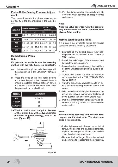
C - Wind a cord around the pilot diameter<br />
of the pinion box with a dynamometer<br />
(balance of good quality), tied at its<br />
end (figure 49).<br />
11<br />
14<br />
D - Pull the dynamometer horizontally and observe<br />
the value (pounds or kilos) recorded<br />
on its scale.<br />
Note :<br />
Note the value recorded with the box rotating<br />
and not the start value. The start value<br />
gives a false reading.<br />
Method Without Using Press<br />
If a press is not available during the service<br />
operation, use the following procedure:<br />
A - Lubricate all the hypoid pinion roller bearings<br />
with the oil specified in the LUBRICA-<br />
TION section;<br />
B - Install the fork/flange of the universal joint<br />
(without the pinion sealer);<br />
C - Immobilize the pinion (through the fork/flange<br />
of the universal joint) using a suitable device;<br />
D - Tighten the pinion nut with the minimum<br />
value specified in the TIGHTENING TOR-<br />
QUES section;<br />
E - Turn the pinion box several times to en-sure<br />
a suitable seating between covers and<br />
cones;<br />
F - Wind a cord around the pilot diameter of the<br />
pinion box with a dynamometer (balance of<br />
good quality), tied at its end. (figure 49);<br />
G - Pull the dynamometer horizontally and observe<br />
the value (pounds or kilos) recorded<br />
on its scale;<br />
Note :<br />
Note the value recorded with the box rotating<br />
and not the start value. The start value<br />
gives a false reading.<br />
H - If after tightening with the maximum limit of<br />
torque, the desired pre-load is not obtained,<br />
replace the wedges by thinner ones and re-<br />
-peat the checking procedure;<br />
I - Remove the fork/flange of the universal joint<br />
and continue to reassemble the differential.<br />
Figure 49<br />
24 <strong>MAINTENANCE</strong> <strong>MANUAL</strong>


