safety - Catalogue (0860.1) - Wieland Electric
safety - Catalogue (0860.1) - Wieland Electric
safety - Catalogue (0860.1) - Wieland Electric
Create successful ePaper yourself
Turn your PDF publications into a flip-book with our unique Google optimized e-Paper software.
S4000<br />
Basic device with time function – SNV 4063KP<br />
Applications<br />
• Protection of people and machinery<br />
• Monitoring of emergency stop applications<br />
• Monitoring of <strong>safety</strong> gates<br />
• Monitoring of interlocking installation with position<br />
switches and integrated locking<br />
• Control of spring-actuated interlocks<br />
• Up to PL e / Category 4 (EN ISO 13849-1)<br />
• Up to SIL CL 3 (EN 62061)<br />
Features<br />
• Stop Category 0 according to EN 60204-1<br />
• Single-channel or two-channel control<br />
• Manual or automatic start<br />
• ON-delay time adjustable in the range 0.15 to 3 s or 1.5 to 30 s<br />
• Reset button monitoring, cross monitoring<br />
• 3 enabling current paths (2 undelayed, 1 ON-delayed)<br />
Function<br />
With supply voltage applied to terminals A1/A2, relays K3 and K4 (terminals<br />
37/38) start with the pre-selected ON-delay time. The ON-delay time t A1 can be<br />
adjusted infinitely in the range 0.15 to 3 s or 1.5 to 30 s according to the device<br />
type. The device is enabled by pressing the reset button. The following operating<br />
modes can be selected:<br />
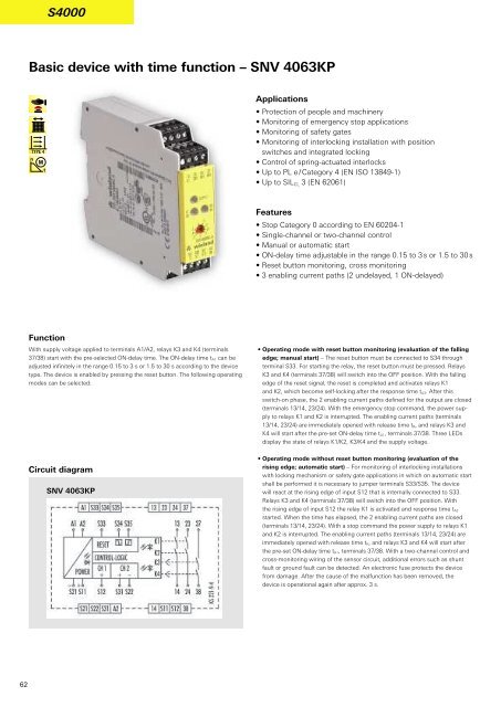
Circuit diagram<br />
SNV 4063KP<br />
• Operating mode with reset button monitoring (evaluation of the falling<br />
edge; manual start) – The reset button must be connected to S34 through<br />
terminal S33. For starting the relay, the reset button must be pressed. Relays<br />
K3 and K4 (terminals 37/38) will switch into the OFF position. With the falling<br />
edge of the reset signal, the reset is completed and activates relays K1<br />
and K2, which become self-locking after the response time t A3. After this<br />
switch-on phase, the 2 enabling current paths defined for the output are closed<br />
(terminals 13/14, 23/24). With the emergency stop command, the power supply<br />
to relays K1 and K2 is interrupted. The enabling current paths (terminals<br />
13/14, 23/24) are immediately opened with release time t R, and relays K3 and<br />
K4 will start after the pre-set ON-delay time t A1, terminals 37/38. Three LEDs<br />
display the state of relays K1/K2, K3/K4 and the supply voltage.<br />
• Operating mode without reset button monitoring (evaluation of the<br />
rising edge; automatic start) – For monitoring of interlocking installations<br />
with locking mechanism or <strong>safety</strong> gate applications in which on automatic start<br />
shall be performed it is necessary to jumper terminals S33/S35. The device<br />
will react at the rising edge of input S12 that is internally connected to S33.<br />
Relays K3 and K4 (terminals 37/38) will switch into the OFF position. With<br />
the rising edge of input S12 the relay K1 is activated and response time t A2<br />
started. When the time has elapsed, the 2 enabling current paths are closed<br />
(terminals 13/14, 23/24). With a stop command the power supply to relays K1<br />
and K2 is interrupted. The enabling current paths (terminals 13/14, 23/24) are<br />
immediately opened with release time t R, and relays K3 and K4 will start after<br />
the pre-set ON-delay time t A1, terminals 37/38. With a two-channel control and<br />
cross-monitoring wiring of the sensor circuit, additional errors such as shunt<br />
fault or ground fault can be detected. An electronic fuse protects the device<br />
from damage. After the cause of the malfunction has been removed, the<br />
device is operational again after approx. 3 s.<br />
62


