Rainwater Installation Guide - Moiz Trading...
Rainwater Installation Guide - Moiz Trading...
Rainwater Installation Guide - Moiz Trading...

Create successful ePaper yourself
Turn your PDF publications into a flip-book with our unique Google optimized e-Paper software.
TRIG1-PT<br />
JULY 2007<br />
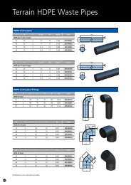
Terrain <strong>Rainwater</strong> Systems<br />
<strong>Installation</strong> <strong>Guide</strong><br />
TERRAIN<br />
DRAINAGE
Distinctive shapes.<br />
Exceptional performance.<br />
Quality product, innovation and outstanding service – the combined promise<br />
that ensures every one of the Terrain five rainwater drainage systems will<br />
surpass your requirements, whatever the installation you’re specifying.<br />
Large or small; residential or commercial; in the public sector or as part of an<br />
industrial development, in terms of both capacity and design aesthetics the<br />
Terrain range of products is impossible to beat.<br />
Each Terrain system comprises fully integrated gutter and downpipe assemblies<br />
as well as outlets for balconies and flat roofs, and includes all the fittings and<br />
accessories needed for easy installation.<br />
Features and benefits<br />
■<br />
■<br />
■<br />
■<br />
■<br />
■<br />
Captive seals in all gutter systems<br />
Combination clipping system for quick reliable installation<br />
Fixing locations positioned outside the wet areas<br />
Expansion markings on ALL gutter fixings<br />
Dry jointed spigot-socket downpipe system<br />
EN607/EN12200/EN1462 Approved<br />
Crescent<br />
Corniche<br />
Streamline<br />
Rapidflow<br />
Omega<br />
Outlets<br />
True half-round profile<br />
Ideal for houses, smaller commercial buildings<br />
and offices. Can drain roof areas up to 122m 2<br />
with a single downpipe. Capacity per outlet<br />
2.54 litres/sec.*<br />
Square profile<br />
A popular, modern system suiting domestic houses,<br />
bungalows and conservatories. Can<br />
drain roof areas up to 149m 2 with a single downpipe.<br />
Capacity per outlet 3.11 litres/sec.*<br />
Large square profile<br />
A high capacity system ideal for commercial<br />
properties and larger houses. Can drain roof<br />
areas up to 294m 2 with a single downpipe. Capacity<br />
per outlet 6.11 litres/sec.*<br />
Deep elliptical profile<br />
A high capacity system suiting all styles of property.<br />
Ideal for large roof areas or areas with higher than<br />
normal rainfall. Can drain roof areas<br />
up to 266m 2 with a single downpipe. Capacity per<br />
outlet 5.53 litres/sec.*<br />
Ogee profile<br />
Ideal for the more distinctive house, also suiting<br />
bungalows and conservatories. Can drain roof areas<br />
up to 242m 2 with a single downpipe. Capacity per<br />
outlet 5.04 litres/sec.*<br />
Roof and Balcony Outlets<br />
Outlets available for all flat roof and balcony<br />
structures and drain vent systems<br />
(For large roof areas use Terrain Siphonics –<br />
see separate catalogue)<br />
*For full capacity specifications please see System Planning on<br />
page 3.
Contents<br />
■ FIXING AND CONNECTIONS 2<br />
Fixing centres and expansion joints 2<br />
■ SYSTEM PLANNING 3<br />
Design principles 3<br />
Flow load calculations 3<br />
■ GUTTER FITTING 4-6<br />
Handling 4<br />
Gutter installation 4<br />
Fixing principles 5<br />
Fixing brackets 5<br />
Support strap 6<br />
Drive-in brackets 6<br />
■ DOWNPIPE FITTING 7-8<br />
Offsets 7<br />
Adjustable pipe clips 7<br />
Outlet guard 7<br />
<strong>Rainwater</strong> shoes 7<br />
<strong>Rainwater</strong> heads 8<br />
Connection to buried pipes 8<br />
Outlet adaptor 8<br />
■ DOWNPIPE FIXING 9<br />
Jointing 9<br />
■ BALCONY OUTLETS 10<br />
■ SMALL ROOF OUTLETS 10<br />
■ LARGE ROOF OUTLETS 11-12<br />
Grid options 11<br />
1
Fixing and connections<br />
Fixing and connections<br />
FIXING CENTRES AND<br />
EXPANSION JOINTS<br />
Thermal movement<br />
When fixing gutter, allowance must be<br />
made for thermal movement and all<br />
Terrain outlets, angles and joint brackets<br />
are engraved with the appropriate<br />
expansion gaps. It is important that the<br />
gutter is correctly fitted into these fittings<br />
taking due care to place the cut end of<br />
the gutter on the line marked. It is<br />
important that the expansion gaps are<br />
maintained when gutter is fitted and must<br />
not be spaced to exceed 4 metres/13ft<br />
centres.<br />
In the case of dry jointing downpipe each<br />
fitting clip has a sight hole provided on<br />
the front of it. (2113.25C, 2216.23 and<br />
the 82mm and 110mm fitting clips do not<br />
have sight holes.)<br />
The purpose of the sight holes is to allow<br />
sight of the top of the pipe<br />
being fitted from below. When this<br />
pipe end obscures half of the aperture you<br />
have the correct expansion gap.<br />
The maximum distance between<br />
expansion joints should not exceed<br />
5.5 metres/18ft.<br />
Applicable to: all Terrain gutter systems<br />
and downpipe assemblies<br />
Maximum distance between:<br />
Gutter support brackets*:<br />
Gutter expansion joints:<br />
Pipe fixing clips:<br />
Pipe expansion joints:<br />
1 metre*<br />
4 metres<br />
2 metres<br />
5.5 metres<br />
*NOTE: Support centres for gutters subject<br />
to risk of heavy snow fall should be<br />
reduced to 800mm (max)<br />
Maximum 4.0 metres<br />
between expansion Joints<br />
For roof outlets<br />
APPLICATION RANGE:<br />
Downpipe<br />
82<br />
mm<br />
110<br />
Downpipe mm<br />
Applicable to: 82mm and 110mm<br />
round pipework used with roof outlets<br />
Maximum distance between:<br />
Vertical pipe fixing clips: 2 metres<br />
Pipe expansion joints: 4 metres †<br />
† NOTE: Anchor expansion couplings with<br />
140 Pipe Fixing Clip to prevent thermal<br />
expansion upthrust from rupturing joint<br />
between roof outlet and finish<br />
Engraved<br />
line<br />
11mm gap<br />
Fig.2<br />
11 mm gap<br />
Maximum<br />
1 metre<br />
Connector<br />
10 mm<br />
expansion<br />
gap<br />
Sight<br />
Moulded<br />
10mm<br />
expansion<br />
gap<br />
Maximum<br />
2.0 m pipe<br />
supports<br />
Fig.3<br />
Pipe & Fitting Clip<br />
Maximum<br />
5.5 m<br />
between<br />
expansion<br />
joints<br />
Fig.1<br />
Fit expansion<br />
coupling immediatly<br />
under roof outlet<br />
111 Expansion<br />
coupling<br />
Anchor coupling<br />
with 140 Pipe<br />
Fixing Clip to<br />
prevent upthrust<br />
due to thermal<br />
expansion from<br />
breaking joint<br />
between outlet<br />
and roof finish<br />
Fig.4<br />
12mm<br />
expansion<br />
gap<br />
140 Pipe Fixing Clip<br />
Maximum<br />
2.0m<br />
between<br />
supports<br />
12mm<br />
Expansion<br />
coupling<br />
Maximum 4.0m<br />
between expansion<br />
2
System planning<br />
System planning<br />
Design principles<br />
Sizing of rainwater installations<br />
There is an approved BS EN method<br />
for the calculation of roof flow load,<br />
and the following general guidelines<br />
and assumptions on sizing of<br />
rainwater installations are based on<br />
this. For detailed guidance on a<br />
particular project, please refer to ‘BS<br />
EN 12056-3:2000 Gravity Drainage<br />
Systems Inside Buildings – Roof<br />
Drainage, Layout and Calculations’, or<br />
contact Terrain Technical Services on<br />
01622 795200.<br />
Rainfall<br />
In the UK, it is generally satisfactory<br />
for eaves gutters to be designed for<br />
a rainfall intensity of 75mm/hr. The<br />
predicted frequency of storms<br />
producing intensities of 75mm/hr is<br />
low, with just one 2 minute duration<br />
fall of such intensity anticipated each<br />
year.<br />
A good factor of safety is therefore<br />
built into any design using these<br />
values. However, when designing for<br />
closed areas such as lightwells, flat<br />
roofs or similar the rainfall intensity<br />
value allowed for should be<br />
increased. Again, please refer to<br />
‘BS EN 12056-3:2000’.<br />
Snow<br />
‘BS EN 12056-3:2000’ sets out<br />
(Section NB4) design requirements<br />
for snow which should be taken<br />
into account. In areas where high<br />
snow loads are common, or where<br />
smooth roofing surfaces are used,<br />
gutter support brackets should be<br />
fixed at a maximum of 800mm<br />
centres.<br />
Wind<br />
There is no requirement to allow for<br />
the effect of wind when designing a<br />
rainwater system for flat roofs or<br />
roofs protected from the wind by<br />
adjacent buildings. However, the<br />
wind and the roof slope can have the<br />
effect of increasing the roof flow<br />
load for unprotected pitched roofs.<br />
This is allowed for in the ‘BS EN<br />
12056-3:2000’ calculation method<br />
by adding half the rise to the roof<br />
span.<br />
Roof Flow Load:<br />
How to calculate it<br />
There are two factors to consider<br />
when calculating flow. Firstly the area<br />
to be drained, or ‘effective roof area’;<br />
and the intensity of rainfall.<br />
For the intensity of rainfall you should<br />
assume 75mm/hr except for enclosed<br />
areas such as lightwells and flat roofs.<br />
Effective Roof Area<br />
Effective Roof Area can be calculated<br />
using the following formula, as<br />
illustrated in Fig.5.<br />
ERA(m 2 ) =(W + H/2) x L (Fig.5)<br />
KEY:<br />
ERA = Effective Roof Area<br />
(square metres)<br />
W = horizontal distance from<br />
eaves to point directly<br />
below ridge<br />
H = vertical rise between<br />
eaves and ridge (metres)<br />
L = gutter length (metres)<br />
Calculating the actual flow<br />
Once you have calculated the ERA,<br />
for 75mm/hr rainfall intensity<br />
FLOW (litres/second) =<br />
ERA (m 2 ) x 0.0208<br />
For other rainfall intensities<br />
FLOW = ERA (m 2 ) x rainfall intensity<br />
(mm/hr)/3600 = litres/second<br />
H<br />
Fig.5<br />
90°<br />
W<br />
L<br />
Flow load calculations<br />
Position A<br />
Position B<br />
Position C<br />
Downpipe<br />
Size/Type (mm)<br />
2100 crescent<br />
68 round<br />
2200 corniche<br />
62 square<br />
2300 streamline<br />
75 square<br />
82 and 110 round<br />
2400 rapidflow<br />
68 and 82 round<br />
2500 omega<br />
62 square<br />
68 round<br />
2100 crescent<br />
68 round<br />
2200 corniche<br />
62 square<br />
2300 streamline<br />
75 square<br />
82 and 110 round<br />
2400 rapidflow<br />
68 and 82 round<br />
2500 omega<br />
62 square<br />
68 round<br />
2100 crescent<br />
68 round<br />
2200 corniche<br />
62 square<br />
2300 streamline<br />
75 square<br />
82 round<br />
110 round<br />
2400 rapidflow<br />
68 and 82 round<br />
2500 omega<br />
62 square<br />
68 round<br />
Area<br />
(m 2 )<br />
Level<br />
gutter<br />
Flow<br />
(l/s)<br />
Gutter<br />
1:350 fall<br />
Area Flow<br />
(m 2 ) (l/s)<br />
46 0.96 61 1.27<br />
53 1.10 72 1.50<br />
123 2.56 147 3.06<br />
105 2.19 133 2.77<br />
96 2.00 121 2.52<br />
37 0.77 49 1.02<br />
42 0.87 58 1.21<br />
103 2.14 123 2.56<br />
86 1.79 109 2.27<br />
77 1.60 97 2.02<br />
92 1.91 122 2.54<br />
113 2.36 149 3.11<br />
241 5.02 286 5.96<br />
242 5.04 286 5.96<br />
242 5.04 294 6.11<br />
210 4.38 266 5.53<br />
192 4.00 242 5.04<br />
Roof outlet flow load: calculation method<br />
For a flat roof (i.e. a roof with a pitch less than 10°),<br />
the effective roof area = the plan area of the relevant part of the roof.<br />
Roof<br />
outlet<br />
part no.<br />
Size<br />
Flow capacity<br />
litres/sec Head of water at outlet<br />
30mm 50mm 100mm<br />
To calculate flow in litres/second for 75mm/hr rainfall intensity:<br />
firstly measure plan area of roof served by each outlet (square metres)<br />
and then multiply area by 0.0208 to obtain flow (litres/second)<br />
NOTE: See Code of Practice BS EN 12056-3:2000 for full details<br />
Roof outlets flow data<br />
The flow rates listed have been established by independent testing carried out<br />
by the <strong>Rainwater</strong> Drainage Design Company using facilities at the Hydraulics<br />
laboratory of Salford University.<br />
2180.2<br />
2180.3<br />
2181.2<br />
2181.3<br />
2170.3<br />
2170.4<br />
2171.3<br />
2171.4<br />
50<br />
82<br />
50<br />
82<br />
82<br />
110<br />
82<br />
110<br />
0.88<br />
2.12<br />
2.00<br />
2.10<br />
9.18<br />
9.29<br />
4.94<br />
5.17<br />
1.18<br />
2.52<br />
2.27<br />
4.89<br />
11.08<br />
14.11<br />
9.24<br />
9.95<br />
1.78<br />
3.21<br />
2.69<br />
7.22<br />
13.67<br />
18.22<br />
16.64<br />
24.18<br />
Note: Figures based on 75mm/hr rainfall intensity<br />
3
Gutter fitting<br />
Gutter fitting<br />
HANDLING<br />
■<br />
■<br />
■<br />
Take all reasonable care when<br />
handling PVC-u, particularly in very<br />
cold conditions<br />
Load and unload loose pipes by hand<br />
In case of mechanical handling, avoid<br />
the use of chains and hooks<br />
On site storage<br />
■<br />
■<br />
■<br />
■<br />
■<br />
■<br />
■<br />
■<br />
Stack pipe lengths:<br />
– either on a flat base<br />
– or on level ground<br />
– or on 75mm x 75mm timber at<br />
1m maximum centres.<br />
Provide side support with<br />
75mm wide battens at 1m centres<br />
(see Fig.6)<br />
Maximum stack: seven layers high<br />
Ideally, stacks should contain one<br />
diameter pipe size only. Where this is<br />
not possible, stack largest diameter<br />
pipes at base of stack. Small pipes<br />
may be nested inside larger pipes<br />
If stored in the open for long periods<br />
or exposed to strong sunlight, cover<br />
the stack with opaque sheeting<br />
Store fittings under cover.<br />
Do not remove from cartons or<br />
packaging until required<br />
Gutters should be kept under similar<br />
storage conditions, but additional<br />
care should be taken to protect the<br />
profile<br />
Store solvent cement and cleaning<br />
fluid in a cool place out of direct<br />
sunlight and away from any heat<br />
source<br />
GUTTER INSTALLATION<br />
General principle<br />
Applicable to: all Terrain gutter systems<br />
■ Lock back clips of fittings in position<br />
and screw fitting to fascia where<br />
applicable<br />
■ Locate back of gutter under rear clip<br />
ensuring that the expansion gap is<br />
correct (see page 2)<br />
■ Pull front of gutter down and push<br />
front clip into position. To release<br />
gutter for adjustment, pull on tab at<br />
front of fitting<br />
Pull to<br />
release<br />
gutter.<br />
Push to<br />
locate<br />
gutter in<br />
Fig.7<br />
1. Lock back clips in<br />
2. Locate back of gutter<br />
3. Pull front of gutter<br />
down and push front<br />
clip into position.<br />
Connecting to other gutter<br />
systems<br />
APPLICATION RANGE:<br />
Crescent<br />
Rapidflow<br />
Applicable to: 2100 CRESCENT and<br />
2400 RAPIDFLOW<br />
■ Gutter Adaptor Clips (2167.4 for<br />
2100 CRESCENT, 2467.5 for 2400<br />
RAPIDFLOW) permit connection<br />
between Terrain systems and PVC-u<br />
guttering of a similar design from<br />
other manufacturers<br />
■ Remove front locking clip from the<br />
side of Terrain fitting which is to take<br />
the connection, BUT DO NOT<br />
DISCARD<br />
■ Lay the other manufacturer’s gutter<br />
into the fitting, ensuring that it sits<br />
correctly within the fitting and that<br />
the expansion gap is correct<br />
(see page 2)<br />
■ Insert one end of the Adaptor Clip<br />
under the back locking clip<br />
■ Holding the adaptor clip in position,<br />
re-insert the front locking clip<br />
■ Check that the gutter is fully seated<br />
within the fixing clip<br />
■ Push the front of the Adaptor Clip<br />
down onto the locking clip seat<br />
1m<br />
Maximum Centres<br />
110mm<br />
160mm with<br />
110mm Inserted<br />
75mm<br />
Minimum<br />
Width<br />
1m<br />
Maximum<br />
Centres<br />
Fig.8 2400 RAPIDFLOW system<br />
4<br />
Fig.6
Gutter fitting<br />
Gutter fitting<br />
FIXING PRINCIPLES<br />
Secure fixing: screw<br />
specification<br />
Applicable to: all Terrain gutter systems<br />
■ All Terrain gutter systems are<br />
designed to withstand maximum<br />
anticipated loading (e.g. heavy snow)<br />
without breaking<br />
■ Any method of fixing the gutter<br />
system to the building fabric<br />
MUST be equally capable of bearing<br />
such loading<br />
■ Assuming fixing to nominal 25mm<br />
thick softwood, fascia screws should<br />
be:<br />
– Size: No.10 roundhead*<br />
zinc-plated<br />
– Length: penetrating wood by<br />
minimum 19mm<br />
*Some fittings are manufactured with<br />
countersunk holes (Omega). In such cases<br />
countersunk screws may be used<br />
Fixing methods<br />
Applicable to: all Terrain gutter systems<br />
Fig.9b<br />
Lugs<br />
Fig.9a 2200 CORNICHE system<br />
Recess<br />
Screw holes for internal<br />
angle behind seal<br />
■<br />
Generally, Terrain gutter fittings<br />
(brackets, outlets, angles) are<br />
designed with:<br />
– EITHER integral fixing lugs<br />
(Fig.9a)<br />
– OR recess(es) (Fig.9b) which<br />
accept a standard support<br />
bracket<br />
IMPORTANT NOTE: Whichever method is<br />
used, ALL fittings must be anchored<br />
■ In some cases, Terrain gutter fittings<br />
are designed with screw fixing holes<br />
behind the seal, eg gutter angle<br />
2354.6.90. If it is not possible to<br />
secure gutter angles through the<br />
screw fixing holes, then support<br />
brackets must be fitted to the gutter<br />
within 150mm of the angle on both<br />
sides<br />
Spacer blocks<br />
APPLICATION RANGE:<br />
Crescent<br />
Corniche<br />
Applicable to: 2100 CRESCENT and<br />
2200 CORNICHE systems<br />
Designed to enable 2100 and 2200<br />
systems to accommodate large tile<br />
overhangs, placing the gutter centrally<br />
beneath the tile edge. Avoids the need to<br />
use a larger gutter system. 2166 Spacer<br />
(rectangular): Steps out gutters by 16mm<br />
2166.22 Spacer (triangular): Allows<br />
gutters to be fixed to 22 1 /2° sloping<br />
fascias<br />
■ Screw fix spacer to fascia through<br />
fixing holes provided<br />
■ Fix bracket THROUGH spacer, solidly<br />
into fascia<br />
FIXING BRACKETS<br />
Fixing adjustable rafter<br />
bracket<br />
Applicable to: all Terrain gutter systems<br />
■ For fixing gutter systems to openended<br />
rafters where no fascia exists<br />
NOTE: Only suitable for rafters in<br />
sound condition<br />
■ Choice of brackets (all adjustable):<br />
Side (2160 and 2360)<br />
Top (2161 and 2361)<br />
■ Fixing to rafter using (minimum)<br />
2 x No.10 roundhead zinc-plated<br />
screws<br />
■ Support bracket secured by single<br />
bolt<br />
■ Pegs on rafter bracket locate in screw<br />
holes of support bracket<br />
Fig.12<br />
(A)<br />
System Adjustment Range<br />
(A)<br />
2100, 2200 65mm<br />
2300, 2400, 2500 75mm<br />
150mm<br />
150mm<br />
Fig.10<br />
Fig.11<br />
5
Gutter fitting<br />
Gutter fitting<br />
SUPPORT STRAP<br />
Gutter fitting support strap<br />
Applicable to: all Terrain gutter systems<br />
■ For use with joint brackets and<br />
running outlets when used with any<br />
rafter bracket<br />
■ Discard PVC-u back plate from rafter<br />
bracket: retain nut and bolt to fix<br />
support strap to brackets<br />
■ Studs prevent support strap<br />
from twisting<br />
Studs<br />
Rafter Bracket<br />
2265 Support Strap<br />
DRIVE-IN BRACKETS<br />
Fixing drive-in brackets<br />
Applicable to: all Terrain gutter systems<br />
■ For fixing gutters where no fascia<br />
board or rafters exist<br />
■ Standard version: 2162 (for 2100<br />
CRESCENT and 2200 CORNICHE<br />
systems)<br />
■ Heavy duty version: 2362 (for 2300<br />
STREAMLINE, 2400 RAPIDFLOW<br />
and 2500 OMEGA systems)<br />
■ Drive spike into mortar at appropriate<br />
height to allow fitting of gutter<br />
support bracket (or drill suitable hole<br />
and mortar spike in)<br />
■ Support bracket held in position by<br />
nut and bolt<br />
■ Adjust height by slackening locking<br />
nuts on threaded stud<br />
Fig.14<br />
NOTE: If used on corbelled brickwork,<br />
ensure sufficient penetration of spike into<br />
mortar to support potential gutter loading<br />
Fig.13<br />
6
Downpipe fitting<br />
Downpipe fitting<br />
OFFSETS<br />
OUTLET GUARD<br />
■<br />
Form an offset (or ‘swan neck’) using<br />
2 x 112.5° standard bends and a cut<br />
length of plain ended pipe<br />
Small offsets<br />
APPLICATION RANGE:<br />
Downpipe<br />
62<br />
mm<br />
Downpipe<br />
75<br />
mm<br />
Applicable to: 62mm and 75mm square<br />
downpipe systems<br />
■ For 62mm square downpipe,<br />
2214.23 Wall Offset provides<br />
25mm offset<br />
A<br />
B<br />
Adjustment Range<br />
A<br />
B<br />
min max min max<br />
63 73 29 39<br />
Gutter outlet guard (9915.25)<br />
APPLICATION RANGE:<br />
Downpipe<br />
68<br />
mm<br />
Downpipe<br />
62<br />
mm<br />
Applicable to: 68mm round and<br />
62mm square downpipe<br />
■ Flexible polyethylene fitting designed<br />
to prevent leaves etc. entering the<br />
downpipe<br />
■ Push-fit into Stop End or Running<br />
Outlet<br />
■<br />
For 75mm square downpipe,<br />
2314.33 Wall Offset provides<br />
57mm offset<br />
Fig.16<br />
Fig.18<br />
Adjustable pipe fitting clip<br />
(2212.23.T)<br />
RAINWATER SHOES<br />
Fig.15<br />
ADJUSTABLE PIPE CLIPS<br />
Adjustable pipe fitting clip<br />
(2112.25.T)<br />
APPLICATION RANGE:<br />
Crescent<br />
Rapidflow<br />
Omega<br />
Downpipe<br />
68<br />
mm<br />
Applicable to: 2100 CRESCENT,<br />
2400 RAPIDFLOW and 2500 OMEGA,<br />
68mm round downpipe<br />
APPLICATION RANGE:<br />
Corniche<br />
Omega<br />
Downpipe<br />
62<br />
mm<br />
Applicable to: 2200 CORNICHE and<br />
2500 OMEGA, 62mm square downpipe<br />
■ Screw back plate to wall using No.10<br />
roundhead screws<br />
■ Locate body over back plate. Ensure<br />
fixing nuts and screws are loosely<br />
fitted onto clip body (the screw<br />
thread should not fully penetrate the<br />
nut)<br />
■ Grip the screw heads firmly and<br />
locate onto the back plate<br />
■ Tighten fixing screws at required<br />
distance from wall<br />
Fixing and locking rainwater<br />
shoes<br />
APPLICATION RANGE:<br />
Applicable to: 68mm round downpipe<br />
systems<br />
■ Locate the moulded nib on retaining<br />
grooves of shoes in one of the five<br />
retaining notches on 2112 or 2113<br />
Fixing Clip<br />
■ Five different positions are possible.<br />
Each ensures both shoe and pipe<br />
above it are fully supported<br />
Retaining<br />
groove<br />
Downpipe<br />
68<br />
mm<br />
Nib<br />
■<br />
Screw back plate to wall using No.10<br />
roundhead screws<br />
■<br />
■<br />
Snap clip body around pipe or fitting.<br />
If around fitting, ensure it is located in<br />
the moulded groove<br />
Locate assembly over back plate and<br />
secure with nut and screw provided at<br />
required distance from wall<br />
Fig.17<br />
Fig.19<br />
7
Downpipe fitting<br />
Downpipe fitting<br />
RAINWATER HEADS<br />
Applicable to: all Terrain Downpipes<br />
■ Direct push-fit connection at correct<br />
distance from wall (Fig.20a)<br />
2111.25 to suit 68mm round<br />
2211.23 to suit 62mm square<br />
2111.3 to suit 82mm round<br />
2111.4 to suit 110mm round<br />
■ Requires 25mm Offset Bend<br />
F2314.33.25 for connection to 75mm<br />
square downpipe at correct distance<br />
from wall (Fig.20b)<br />
2311.33 to suit 75mm square<br />
CONNECTION TO BURIED<br />
PIPES<br />
APPLICATION RANGE:<br />
Downpipe<br />
68<br />
mm<br />
Downpipe<br />
62<br />
mm<br />
Downpipe<br />
75<br />
mm<br />
Applicable to: 68mm round and 62mm<br />
or 75mm square downpipe systems<br />
■ Use EPDM rubber drain adaptors to<br />
connect downpipes to 82mm and<br />
110mm buried drains<br />
<strong>Rainwater</strong> pipe<br />
EPDM<br />
adaptor<br />
Socket<br />
110 mm<br />
UPVC<br />
OUTLET ADAPTOR<br />
Screwed outlet adaptor (2368)<br />
APPLICATION RANGE:<br />
Streamline<br />
Downpipe<br />
75<br />
mm<br />
Applicable to: 2300 STREAMLINE with<br />
75mm square downpipe<br />
■ Enables downpipe to be positioned<br />
anywhere along a gutter length<br />
■ Using Terrain Hole Cutter 2105.3<br />
drill 76mm diameter hole in centre of<br />
base of gutter<br />
■ Unscrew the two parts of the adaptor<br />
and push top part with screw thread<br />
through hole in gutter outlet guard<br />
■ Screw the two parts of the adaptor<br />
together so that the gutter is clamped<br />
tightly<br />
Fig.20a<br />
Fig.20b<br />
<strong>Rainwater</strong> pipe<br />
EPDM<br />
adaptor<br />
Drain<br />
Fig.21<br />
Fig.22<br />
8
Downpipe fixing<br />
Downpipe fixing<br />
JOINTING<br />
Dry jointing<br />
APPLICATION RANGE:<br />
Downpipe<br />
62<br />
mm<br />
Solvent cement jointing<br />
APPLICATION RANGE:<br />
110<br />
Downpipe mm<br />
Applicable to: Terrain 110mm round<br />
downpipe assemblies<br />
■<br />
■<br />
Withdraw pipe until mark is 12mm<br />
from socket to provide required<br />
expansion gap<br />
Anchor the expansion joint with a<br />
pipe fixing clip OR (if not practical)<br />
anchor a fitting within 1 metre of<br />
the joint<br />
Downpipe<br />
75<br />
mm<br />
Downpipe<br />
68<br />
mm<br />
Downpipe<br />
82<br />
mm<br />
Applicable to: Terrain 62mm/75mm<br />
square downpipe assemblies and<br />
68mm/82mm round downpipe<br />
assemblies<br />
■ Fully support all downpipe and joint<br />
fittings with fixing clips positioned at<br />
correct intervals<br />
■ Install fittings with the socket facing<br />
upstream<br />
NOTE: All downpipe fittings – except<br />
shoes – are socket/spigot<br />
■ Ensure pipe ends are cut square and<br />
deburred before connection to fitting<br />
■ Position pipe and fitting clip in<br />
moulded groove on fitting<br />
■ Check clip is correctly positioned, by<br />
ensuring that the expansion gap is<br />
marked<br />
■ Use the sight hole in the front of the<br />
clip to achieve the correct expansion<br />
gap<br />
NOTE: The 2100.3 is a dry joint system for<br />
external use. If used internally, it must be<br />
solvent welded to make an air-tight<br />
system. Alternatively, the 100.3 soil system<br />
can be used.<br />
■ Cut pipe square, deburr and clean<br />
mating surfaces with 9101 Cleaning<br />
Fluid<br />
■ Coat mating surfaces with 9100<br />
Liquid Weld, using a clean brush<br />
■ Assemble joint immediately, removing<br />
any excess cement with a clean rag<br />
Initial set: 3-4 minutes<br />
Final set: 12 hours<br />
Fig.24<br />
CAUTION: Closely follow directions for use<br />
of solvent cement as printed on the<br />
container label<br />
Seal ring jointing<br />
APPLICATION RANGE:<br />
110<br />
Downpipe mm<br />
Fig.25<br />
Conversion of solvent weld<br />
socket to ring seal joint<br />
APPLICATION RANGE:<br />
Downpipe<br />
82<br />
mm<br />
110<br />
Downpipe mm<br />
Applicable to: 82mm and 110mm<br />
round solvent cemented downpipe<br />
assemblies, using 109.3/109.4 Seal Ring<br />
Adaptor<br />
Under normal use fit 109 Adaptor to<br />
upstream socket only<br />
■ Clean mating surfaces with 9101<br />
Cleaning Fluid<br />
■ Fit ring seal into 109 Collar<br />
■ Carefully apply solvent cement to<br />
mating surfaces<br />
■ Assemble immediately, applying firm<br />
even pressure until collar is correctly<br />
positioned<br />
Expansion<br />
gap<br />
Fig.23 2200 CORNICHE system<br />
Applicable to: Terrain 110mm round<br />
downpipe assemblies<br />
REQUIREMENT: To create a 12mm<br />
expansion gap at a pipe joint to allow<br />
pipes to expand without distorting the<br />
pipework<br />
■<br />
■<br />
File square cut pipe to provide<br />
45° chamfer. (Do not chamfer to a<br />
knife edge.) Lubricate rubber seal<br />
with 9136 Lubricant<br />
Push pipe fully into socket.<br />
Mark pipe as shown (Fig.25)<br />
Fig.26<br />
9
Balcony outlets<br />
Balcony outlets<br />
Installing screed finish<br />
balcony outlet<br />
Applicable to: 2172 Balcony Outlet<br />
■ Remove grid<br />
■ Position spacer on locating pegs<br />
■ Replace screws temporarily to prevent<br />
ingress of concrete<br />
■ Lay screed to the level of the top<br />
edge of the spacer<br />
■ Remove screws and replace grid<br />
■ Dress flashing over the rear upstand<br />
■ Tuck flashing into brickwork, joint and<br />
point<br />
Installing asphalt finish<br />
balcony outlet<br />
Applicable to: 2174 Balcony Outlet<br />
■ Remove grid<br />
■ Temporarily replace screws to prevent<br />
ingress of asphalt<br />
■ Apply a suitable primer or bonding<br />
agent up to engraved line on outlet<br />
body<br />
■ Apply asphalt layer: dress over outer<br />
rim and down to engraved line on<br />
outlet body<br />
■ Remove screws<br />
■ Offer up grid and check correct angle<br />
of dressing<br />
■ Fit washer and grid, and secure with<br />
screws<br />
NOTE: The polypropylene washer allows<br />
the grid to be easily removed for<br />
maintenance/clearing<br />
Connection to downpipes<br />
Applicable to: 2172 and 2174 Balcony<br />
Outlets<br />
■ For 68mm round downpipe (2100):<br />
use 2173.3.25 Socket Adaptor<br />
■ For 62mm square downpipe (2200):<br />
use 2273.3.23 Socket Adaptor<br />
■ For 82mm round downpipe (2100.3):<br />
connect direct to balcony outlet<br />
socket<br />
■ Solvent-weld all joints (see page 9)<br />
2273.3.23<br />
2172 or 2174<br />
2173.3.25<br />
Fig.27<br />
Fig.29<br />
2200.23 2100.3 2100.25<br />
Fig.28<br />
Small roof outlets<br />
Small roof outlets<br />
Fixing small roof outlet to<br />
proprietary plastic finish<br />
Applicable to: all 2180 and<br />
2181 Roof Outlets<br />
■ Apply recommended adhesive to<br />
flange of outlet body<br />
■ Dress plastic material over flange to<br />
the edge of opening<br />
■<br />
■<br />
Dress second and third layers over the<br />
flange to the edge of the opening<br />
Secure the flat or domed grid with<br />
the brass screw supplied, lightly<br />
clamping the edge of the second and<br />
third layers of felt<br />
NOTE: 2180 and 2181 outlets are not<br />
suitable for use with hot asphalt<br />
Fig.30<br />
■<br />
Secure the flat or domed grid with<br />
brass screw supplied, lightly clamping<br />
the roof finish material in position<br />
Fixing small roof outlet to<br />
mineral felt finish<br />
Applicable to: all 2180 and<br />
2181 Roof Outlets<br />
■ Apply suitable bitumastic primer to<br />
flange of outlet body<br />
■ Apply liquid bitumen or activator to<br />
roof and prepared area of flange<br />
■ Lay first layer of felt to edge of flange<br />
2180 2181<br />
Bond felt to<br />
UPVC flange<br />
Solvent weld<br />
pipe<br />
Screw to<br />
roof deck<br />
Fittings<br />
2180.2 + 207.2.92 55<br />
2181.2 + 207.2.92<br />
2180.3 + 107.3.92<br />
2181.3 + 107.3.92<br />
outlet<br />
size<br />
(mm)<br />
55<br />
82<br />
82<br />
dimension<br />
A (mm)<br />
min max<br />
73 118<br />
73 118<br />
89 168<br />
89 168<br />
10
Balcony outlets<br />
Balcony outlets<br />
Connecting spigot/socket<br />
bends (small roof outlets)<br />
Applicable to: all small diameter roof<br />
outlets<br />
A<br />
Fig.31 2181.2 Domed Outlet<br />
(small diameter)<br />
11
Large roof outlets<br />
Large roof outlets<br />
GRID OPTIONS<br />
Fixing to proprietary plastic<br />
finish<br />
Applicable to: all 2170 and<br />
2171 Roof Outlets<br />
2170.4 2171.4 2171.4A 2171.44<br />
■<br />
■<br />
■<br />
■<br />
Apply recommended adhesive to<br />
bowl and flange of outlet body<br />
Lay plastic material over roof outlet<br />
Dress over flange and bowl to the<br />
level of the upstand<br />
Secure grid and washer with screws<br />
supplied (see Fig.32 for alternative<br />
grids)<br />
NOTE: The polypropylene washer allows<br />
the grid to be easily removed for<br />
maintenance/clearing<br />
Fig.32<br />
NOTE: 2170 flat roof outlet is not suitable for vehicular traffic<br />
Fixing to asphalt finish<br />
Applicable to: all 2170 and<br />
2171 Roof Outlets<br />
■ Apply suitable bitumastic primer or<br />
bonding agent to bowl and flange of<br />
outlet body<br />
■ Dress a 19mm layer of asphalt over<br />
flange and bowl to level of upstand<br />
■ Offer up selected grid (see Fig.32 for<br />
alternative grids) check correct angle<br />
of dressing and engagement of<br />
screws<br />
■ Secure grid and washer in position<br />
with screws supplied<br />
NOTE: The polypropylene washer allows<br />
the grid to be easily removed for<br />
maintenance/clearing<br />
Fixing to mineral felt finish<br />
Applicable to: all 2170 and<br />
2171 Roof Outlets<br />
■ Apply suitable bitumastic primer or<br />
bonding agent to bowl and flange of<br />
outlet body<br />
■ Apply liquid bitumen or activator to<br />
roof and prepared areas of outlet<br />
body<br />
■ Lay first layer of felt to edge of flange<br />
■ Lay second and third layers over roof<br />
outlet<br />
■ Dress down into bowl to the upstand<br />
■ Secure grid and washer in position<br />
with screws supplied<br />
NOTE: The polypropylene washer allows<br />
the grid to be easily removed for<br />
maintenance/clearing<br />
Fig.35 2171.4 Domed Outlet<br />
Anchoring on thin or uneven<br />
roof structures<br />
Applicable to: all 2170 and<br />
2171 Roof Outlets<br />
Three-layer felt on insulation material<br />
over profiled metal decking<br />
Fig.33 2171.4 Domed Outlet<br />
Fig.34 2171.4 Domed Outlet<br />
Three-layer felt on<br />
thin timber decking<br />
Fig.36 2171.4 Domed Outlet<br />
12<br />
12
Large roof outlets<br />
Large roof outlets<br />
Connecting spigot/socket<br />
bends (large roof outlets)<br />
Applicable to: all large roof outlets<br />
Fittings<br />
2170.3 + 107.3.92 82<br />
2171.3 + 107.3.92<br />
outlet<br />
size<br />
(mm)<br />
82<br />
dimension<br />
A (mm)<br />
min max<br />
140 219<br />
140 219<br />
General fixing details<br />
Applicable to: balcony and roof outlets<br />
■ Solvent weld pipe-end, or spigot of<br />
bend, to roof outlet (for jointing<br />
techniques, see page 9)<br />
2170.4 + 107.4.92<br />
2171.4 + 107.4.92<br />
110<br />
110<br />
146 257<br />
146 257<br />
■<br />
Locate outlet body in roof structure<br />
and check that a suitable rigid fixing<br />
can be made<br />
A<br />
■<br />
Screw down outlet firmly to roof<br />
structure<br />
Fig.37 2171.4 Domed Outlet<br />
■<br />
■<br />
Remove grid<br />
Apply selected roof finish<br />
HELPING YOU SOLVE PROBLEMS<br />
Terrain products are backed by a comprehensive Technical Advisory<br />
Service, which is here to provide you with advice and design<br />
guidance on all aspects of above and below ground drainage.<br />
Telephone 01622 795200 Fax 01622 792564.<br />
Planning and development stage<br />
The technical services available to help you at this stage include:<br />
– Drainage system design, including detailed drawings<br />
– Specification, product scheduling and estimating<br />
– Design and production of bespoke fittings to meet specific<br />
application requirements<br />
– NBS Specification clauses available<br />
The Terrain Fabrication Service helps specifiers and contractors<br />
overcome problems both at the design stage, and on site. The<br />
Service can provide solutions to even the most demanding problems<br />
by fabricating special components to order.<br />
Quality and assurance<br />
Terrain is accredited to BS EN ISO 9001:2000 Management Systems.<br />
All systems are manufactured to the relevant European Standard<br />
and where applicable certified to British Standard.<br />
– EN 607 Eaves Gutters and Fittings made from PVC-u<br />
– EN 1462 Brackets for Eaves Gutters<br />
– EN 12200 Plastic rainwater piping for above ground external<br />
use PVC-u<br />
13<br />
13
Notes<br />
Notes<br />
14<br />
14
Commercial Piping and<br />
Sanitary Systems<br />
Polypipe Terrain<br />
TERRAIN<br />
DRAINAGE<br />
Terrain Drainage<br />
New Hythe Business Park<br />
College Road<br />
Aylesford<br />
TING PLUM<br />
NG AND HEAT<br />
EATING PLUMBI<br />
PLUMBING<br />
AND HEATING<br />
BING AND HEATI<br />
ATING PLUMB<br />
G AND HE<br />
Plumbing and Heating<br />
Kent ME20 7PJ<br />
Tel: 01622 795200<br />
Fax: 01622 792564<br />
Pressure Pipes<br />
Sanitary<br />
Bishop Meadow Road<br />
Loughborough<br />
Leicestershire LE11 5RE<br />
Ventilation<br />
Tel: 08452 700886<br />
Fax: 08452 760076<br />
commercialenquiries@polypipe.com<br />
W<br />
MENT WAT<br />
MANAGEMENT W<br />
GEMENT WATER<br />
WATER<br />
MANAGEMENT<br />
R MANAGEMENT W<br />
EMENT WATER MAN<br />
ANAGEMENT<br />
Water Management<br />
www.polypipe.com<br />
www.terraindrainage.com