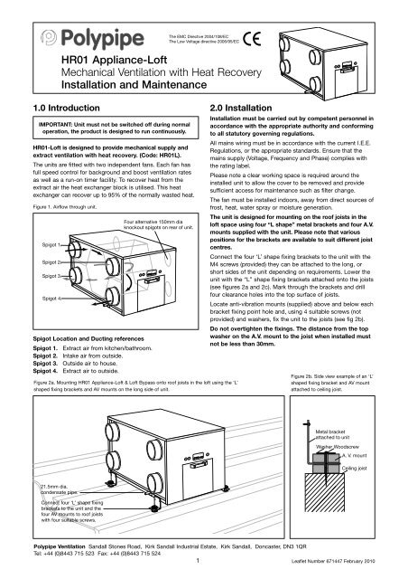
HR01 Appliance-Loft Mechanical Ventilation with Heat Recovery ...
HR01 Appliance-Loft Mechanical Ventilation with Heat Recovery ...
HR01 Appliance-Loft Mechanical Ventilation with Heat Recovery ...

Create successful ePaper yourself
Turn your PDF publications into a flip-book with our unique Google optimized e-Paper software.
The EMC Directive 2004/108/EC<br />
The Low Voltage directive 2006/95/EC<br />
<strong>HR01</strong> <strong>Appliance</strong>-<strong>Loft</strong><br />
<strong>Mechanical</strong> <strong>Ventilation</strong> <strong>with</strong> <strong>Heat</strong> <strong>Recovery</strong><br />
Installation and Maintenance<br />
1.0 Introduction<br />
IMPORTANT: Unit must not be switched off during normal<br />
operation, the product is designed to run continuously.<br />
<strong>HR01</strong>-<strong>Loft</strong> is designed to provide mechanical supply and<br />
extract ventilation <strong>with</strong> heat recovery. (Code: <strong>HR01</strong>L).<br />
The units are fitted <strong>with</strong> two independent fans. Each fan has<br />
full speed control for background and boost ventilation rates<br />
as well as a run-on timer facility. To recover heat from the<br />
extract air the heat exchanger block is utilised. This heat<br />
exchanger can recover up to 95% of the normally wasted heat.<br />
Figure 1. Airflow through unit.<br />
Spigot 1.<br />
Spigot 2.<br />
Spigot 3.<br />
Spigot 4.<br />
Spigot Location and Ducting references<br />
Spigot 1. Extract air from kitchen/bathroom.<br />
Spigot 2. Intake air from outside.<br />
Spigot 3. Outside air to house.<br />
Spigot 4. Extract air to outside.<br />
Four alternative 150mm dia<br />
knockout spigots on rear of unit.<br />
Figure 2a. Mounting <strong>HR01</strong> <strong>Appliance</strong>-<strong>Loft</strong> & <strong>Loft</strong> Bypass onto roof joists in the loft using the ‘L’<br />
shaped fixing brackets and AV mounts on the long side of unit.<br />
2.0 Installation<br />
Installation must be carried out by competent personnel in<br />
accordance <strong>with</strong> the appropriate authority and conforming<br />
to all statutory governing regulations.<br />
All mains wiring must be in accordance <strong>with</strong> the current I.E.E.<br />
Regulations, or the appropriate standards. Ensure that the<br />
mains supply (Voltage, Frequency and Phase) complies <strong>with</strong><br />
the rating label.<br />
Please note a clear working space is required around the<br />
installed unit to allow the cover to be removed and provide<br />
sufficient access for maintenance such as filter change.<br />
The fan must be installed indoors, away from direct sources of<br />
frost, heat, water spray or moisture generation.<br />
The unit is designed for mounting on the roof joists in the<br />
loft space using four “L shape” metal brackets and four A.V.<br />
mounts supplied <strong>with</strong> the unit. Please note that various<br />
positions for the brackets are available to suit different joist<br />
centres.<br />
Connect the four ‘L’ shape fixing brackets to the unit <strong>with</strong> the<br />
M4 screws (provided) they can be attached to the long, or<br />
short sides of the unit depending on requirements. Lower the<br />
unit <strong>with</strong> the “L” shape fixing brackets attached onto the joists<br />
(see figures 2a and 2c). Mark through the brackets and drill<br />
four clearance holes into the top surface of joists.<br />
Locate anti-vibration mounts (supplied) above and below each<br />
bracket fixing point hole and, using 4 suitable screws (not<br />
provided) and washers, fix the unit to the joists (see fig 2b).<br />
Do not overtighten the fixings. The distance from the top<br />
washer on the A.V. mount to the joist when installed must<br />
not be less than 30mm.<br />
Figure 2b. Side view example of an ‘L’<br />
shaped fixing bracket and AV mount<br />
attached to ceiling joist.<br />
Metal bracket<br />
attached to unit<br />
Washer Woodscrew<br />
A. V. mount<br />
Ceiling joist<br />
21.5mm dia.<br />
condensate pipe.<br />
Connect four ‘L’ shape fixing<br />
brackets to the unit and the<br />
four AV mounts to roof joists<br />
<strong>with</strong> four suitable screws.<br />
Polypipe <strong>Ventilation</strong> Sandall Stones Road, Kirk Sandall Industrial Estate, Kirk Sandall, Doncaster, DN3 1QR<br />
Tel: +44 (0)8443 715 523 Fax: +44 (0)8443 715 524<br />
1<br />
Leaflet Number 671447 February 2010
Installation and Maintenance<br />
<strong>HR01</strong> <strong>Appliance</strong>-<strong>Loft</strong><br />
Installation cont.<br />
Figure 2c. Mounting <strong>HR01</strong> <strong>Appliance</strong>-<strong>Loft</strong> & <strong>Loft</strong> Bypass onto roof joists using the ‘L’ shaped fixing brackets and AV mounts on the short side of the unit.<br />
Connect four ‘L’ shape fixing<br />
brackets to the unit and the four<br />
AV mounts to roof joists <strong>with</strong><br />
four suitable screws.<br />
21.5mm dia.<br />
condensate pipe.<br />
2.1 Condensate Drain<br />
1. Remove top cover and remove heat exchanger.<br />
The condensate outlet can then be seen at the base of<br />
the unit. Using a 90 Deg bend and suitable length of<br />
¾” / 21.5mm diameter overflow pipe (not supplied) take<br />
the condensate to the outside of the unit (can be taken<br />
to either side of the unit as required).<br />
Suitable adhesive should be used for all connections.<br />
2. The drain should run through a secondary trap before<br />
being discharged through the eaves or into the waste<br />
water system.<br />
3. Pour a little water into the drip tray to create an air trap.<br />
Figure 3. Plan view of unit showing drip tray and condensate drain.<br />
Drain Tray<br />
21.5mm dia. condensate<br />
drain alternative position<br />
2.2 Extract/input areas<br />
The unit is designed to extract air from all wet rooms<br />
e.g. bathroom, kitchen, en-suite, utility room (<strong>with</strong> sink).<br />
WC’s do not need to be ventilated if openable windows are<br />
fitted. Supply air should be to all habitable rooms e.g. bedrooms<br />
and lounge. Extract / input grilles should be adjustable<br />
valve types (not supplied).<br />
2.3 Ducting<br />
1. If the unit has been specified as SAP appendix Q installation<br />
the use of flexible is prohibited. If flexible ducting is to be<br />
used it should be kept to a minimum and should always be<br />
pulled taught.<br />
2. The unit is supplied <strong>with</strong> 150mm and 125mm outlets. It is<br />
recommended that 150mm ducting be used from outside<br />
to the unit and 125mm used from the unit to the dwelling<br />
rooms. To prevent condensation on the ducting they should<br />
be insulated externally vapour-proof as far as the unit.<br />
3. Ducting layout plans should be adhered to if available.<br />
4. It is recommended the 204 x 60mm ducting be used and<br />
the number of 90 Deg bends be kept to a minimum.<br />
5. Ducting joints must be sealed <strong>with</strong> duct tape and/or silicone<br />
sealant.<br />
For further information refer to Building Regulations Part F and<br />
BRE appendix Q website.<br />
21.5mm dia.<br />
condensate drain<br />
IMPORTANT: Any air intake terminal MUST be installed<br />
in accordance <strong>with</strong> the appropriate regulation.<br />
As a guide, the BS5440 series of British Standards<br />
deals <strong>with</strong> this issue and currently states that an air<br />
intake must be at a minimum distance of 300mm from<br />
a gas boiler balanced flue. Installers are advised to be<br />
aware of the requirements of this standard when<br />
installing ‘through the wall’ supply air ducting.<br />
Similarly, supply and extract air grilles should be at<br />
least 300mm apart.<br />
2<br />
Leaflet Number 671447 February 2010
Installation and Maintenance<br />
<strong>HR01</strong> <strong>Appliance</strong>-<strong>Loft</strong><br />
Installation cont.<br />
Figure 4. Main unit components shown <strong>with</strong> front and lid removed.<br />
Figure 5.<br />
G4 removable filter.<br />
(Code: <strong>HR01</strong>FG4).<br />
<strong>Heat</strong> exchanger.<br />
Four optional 150mm dia.<br />
knockout spigot locations on<br />
rear of unit.<br />
If required for use cut through<br />
the acoustic foam round the<br />
circumference of the knockout.<br />
(see figure 5)<br />
G4 removable filter.<br />
(Code: <strong>HR01</strong>FG4).<br />
Adjustment potentiometers and<br />
indication lights.<br />
3.0 Dimensions (mm)<br />
View from front (4 X 125mm spigots)<br />
Side view<br />
430<br />
840<br />
Condensate<br />
Drain<br />
450<br />
21.5mm dia.<br />
condensate<br />
drain alternative<br />
position<br />
View from top<br />
3<br />
Leaflet Number 671447 February 2010
Installation and Maintenance<br />
<strong>HR01</strong> <strong>Appliance</strong>-<strong>Loft</strong><br />
4.0 Electrical Connection<br />
Please note: the electrical connection of the unit must be be carried<br />
out by a qualified electrician.<br />
IMPORTANT: For good EMC engineering practice, any<br />
sensor cables or switched live cables should not be<br />
placed <strong>with</strong>in 50mm of other cables or on the same<br />
metal cable tray as other cables.<br />
The unit is supplied <strong>with</strong> a flexible cord for connection to the<br />
mains supply.<br />
Electrical details:-<br />
Voltage: 240V 1ph 50Hz<br />
Consumption: 75W (max) 0.6 amps<br />
Fuse rating: 3 Amp<br />
NOTE: This unit must be earthed<br />
The three core cable from the mains power supply should be<br />
connected to a fixed wiring installation, via a fused isolator, in<br />
accordance <strong>with</strong> current IEE wiring regulations.<br />
Figure 5a. Power supply PCB.<br />
230V in, 24V dc out.<br />
Internal wiring<br />
Figure 5b.<br />
Control PCB. 24V<br />
Connections for<br />
optional controls<br />
Volt free relay<br />
contacts.<br />
Fault<br />
Run<br />
Switch to deactivate<br />
continuous trickle<br />
Fan connections<br />
230V IN<br />
50Hz<br />
Mains<br />
SWL N L<br />
Connection to supply cord<br />
Earth point<br />
Unit serving kitchen and bathroom<br />
Figure 6.<br />
MAINS<br />
230V<br />
50Hz<br />
N<br />
L<br />
Fuse 2A<br />
Light<br />
switch<br />
(Double<br />
Pole)<br />
Room<br />
light<br />
3 Pole<br />
isolator<br />
Green/yellow<br />
Blue<br />
Brown<br />
Black<br />
Supply cord<br />
from unit<br />
Kitchen switch<br />
Summer<br />
bypass<br />
switch<br />
Grey (only used<br />
on bypass unit)<br />
Unit serving kitchen and two bathrooms<br />
Figure 7.<br />
MAINS<br />
230V<br />
50Hz<br />
N<br />
L<br />
Fuse 2A<br />
Light<br />
switches<br />
(Double<br />
Pole)<br />
Kitchen switch<br />
Room<br />
lights<br />
3 Pole<br />
isolator<br />
Green/yellow<br />
Blue<br />
Brown<br />
Black<br />
Summer<br />
bypass<br />
switch<br />
Grey (only used<br />
on bypass unit)<br />
Supply cord<br />
from unit<br />
4<br />
Leaflet Number 671447 February 2010
Installation and Maintenance<br />
<strong>HR01</strong> <strong>Appliance</strong>-<strong>Loft</strong><br />
Electrical connection cont.<br />
Optional Connections<br />
Ecosmart control (see figure 5a)<br />
(a) J11/12/13<br />
The IDC plug-in connectors are provided for the connection of<br />
compatible sensors.<br />
NOTE: Do not run the data cable in the same conduit as the<br />
mains cable and leave a 50mm separation <strong>with</strong> any power<br />
cables.<br />
LED Indication<br />
PWR GREEN: Power on and OK,<br />
RED:<br />
Standby LED on when fan is not running.<br />
As the unit runs continuously this LED<br />
should be off. If it is illuminated locate the<br />
trickle switch and change its position.<br />
Fan 1 GREEN: Fan 1 is running, RED: Fan 1 faulty.<br />
Fan 2 GREEN: Fan 2 is running, RED: Fan 2 faulty.<br />
(b) Volt Free Relay Contacts<br />
Note that the volt free contacts are not fused. If these are used<br />
to power any external equipment, the installer must provide<br />
adequate fusing or other protections. These contacts are rated<br />
at 5A resistive, 0.5A inductive.<br />
Run connections (J5) - These contacts are closed when the<br />
fan is running.<br />
Fault connections (J7) - No fault = the contacts are closed.<br />
Fault = the contacts are opened (this includes no power<br />
supply at the unit).<br />
5.0 Ancillaries<br />
<strong>HR01</strong>-PIR Sensor<br />
<strong>HR01</strong>-Humidistat Sensor<br />
<strong>HR01</strong>-System Monitor<br />
(Code: <strong>HR01</strong>P)<br />
(Code: <strong>HR01</strong>H)<br />
(Code: <strong>HR01</strong>M)<br />
(c) Data Cable installation<br />
A 4-core data cable is used to connect devices such as<br />
sensors to the fan and for interconnecting multiple fan units.<br />
Do not run data cable in the same conduit as the mains cables<br />
and ensure there is a 50mm separation between the data<br />
cable and other cables. The maximum cable run between any<br />
two devices is 300m when it is installed in accordance <strong>with</strong><br />
the instructions.<br />
Please note that the total data cable length used in any<br />
system must be less than 1000m. Keep the number of cable<br />
joints to a minimum to ensure the best data transmission<br />
efficiency between devices.<br />
5<br />
Leaflet Number 671447 February 2010
Installation and Maintenance<br />
6.0 Commissioning<br />
1. For the required airflow rates refer to the design<br />
specification for the property or refer to Building<br />
Regulations Part F.<br />
2. The unit is supplied <strong>with</strong> control of both the normal<br />
airflow and boost airflow. (see figure below).<br />
3. Commissioning should be carried out using a moving<br />
vane anemometer in conjunction <strong>with</strong> a hood.<br />
4. Once commissioned the house owner / tenant should<br />
be informed that the unit should not be adjusted as it<br />
will have a detrimental effect on the indoor air quality<br />
and could result in condensation and mould growth.<br />
Figure 8. Detail of unit control on side panel.<br />
8.0 Replacement of Parts<br />
Should any component need replacing Polypipe keep extensive<br />
stocks for quick delivery. Ensure that the unit is electrically<br />
isolated, before carrying out any work.<br />
When ordering spare parts, please quote the serial number<br />
of the unit and the ARC number of the purchase if possible.<br />
(This information will be available on the fan label).<br />
9.0 Warranty<br />
<strong>HR01</strong> <strong>Appliance</strong>-<strong>Loft</strong><br />
Standard warranty starts from the day of purchase or delivery.<br />
Polypipe extend the warranty from one to three years on<br />
receipt of the warranty card attached and proof of delivery/<br />
purchase, providing this is returned <strong>with</strong>in the first year.<br />
The warranty covers all parts proven to be faulty at point of<br />
manufacture but excludes problems arising from incorrect<br />
installation. In this instance, if a Polypipe engineer is required<br />
to attend site the call out will be chargeable.<br />
This warranty is conditional upon evidence of planned<br />
maintenance and does not extend to consumable items.<br />
Damaged appliances must not be installed but returned to<br />
point of purchase.<br />
10.0 Service Enquiries<br />
Polypipe can assist you in all aspects of service. Our service<br />
department will be happy to provide any assistance required,<br />
initially by telephone and If necessary arrange for an<br />
engineer to call.<br />
7.0 Maintenance/Cleaning<br />
IMPORTANT: Isolation - Before commencing work make<br />
sure that the unit, switched live and control are electrically<br />
isolated from the mains supply and switched live supply.<br />
1. Replace filters every 5 years. Remove the top cover and<br />
slide out the two G4 filters fitted either side of the heat<br />
exchanger. Replace <strong>with</strong> new filters.<br />
2. Inspect heat exchanger every 5 years. Generally check<br />
for damage and security of components. Refit top cover.<br />
3. Inspecting motors. Motors can be accessed through<br />
removal side panels.<br />
Figure 9. Removing filters.<br />
6<br />
Leaflet Number 671447 February 2010
Notes<br />
7<br />
Leaflet Number 671447 February 2010
Installation and Maintenance<br />
<strong>HR01</strong> <strong>Appliance</strong>-<strong>Loft</strong><br />
11.0 Warranty Card <strong>HR01</strong> <strong>Appliance</strong>-<strong>Loft</strong><br />
*Name:<br />
*Address:<br />
*Postcode:<br />
*Telephone:<br />
Email:<br />
*Model:<br />
*Serial No:<br />
Installer:<br />
Installer Address:<br />
*Date Installed:<br />
*Date Purchased:<br />
Retailer:<br />
Retailer Location:<br />
May we send you relevant product information and remind you when service is due<br />
Your details will not be disclosed to any third party.<br />
*Data required<br />
Return <strong>with</strong> proof of delivery/purchase to:<br />
Polypipe <strong>Ventilation</strong><br />
Sandall Stones Road,<br />
Kirk Sandall Industrial Estate,<br />
Kirk Sandall,<br />
Doncaster, DN3 1QR<br />
Tel: +44 (0)8443 715 523<br />
Fax: +44 (0)8443 715 524<br />
Technical or commercial considerations may, from time to time, make it necessary to alter the design, performance and<br />
dimensions of equipment and the right is reserved to make such changes <strong>with</strong>out prior notice.<br />
8<br />
Leaflet Number 671447 February 2010
The EMC Directive 2004/108/EC<br />
The Low Voltage directive 2006/95/EC<br />
<strong>HR01</strong> <strong>Appliance</strong>-Wall<br />
<strong>Mechanical</strong> <strong>Ventilation</strong> <strong>with</strong> <strong>Heat</strong> <strong>Recovery</strong><br />
Installation and Maintenance<br />
1.0 Introduction<br />
Figure 2. Fixing the mounting bracket to the wall.<br />
IMPORTANT: Unit must not be switched off during normal<br />
operation, the product is designed to run continuously.<br />
<strong>HR01</strong>-Wall is designed to provide mechanical supply and<br />
extract ventilation <strong>with</strong> heat recovery. (Code: <strong>HR01</strong>W).<br />
The unit is fitted <strong>with</strong> two independent fans. Each fan has full<br />
speed control for background and boost ventilation rates as<br />
well as a run-on timer facility. To recover heat from the extract<br />
air the heat exchanger block is utilised. This heat exchanger<br />
can recover up to 95% of the normally wasted heat.<br />
Figure 1. Airflow through unit.<br />
Figure 3. Fixing the mounting<br />
bracket to the rear of unit.<br />
Figure 4. Mounting the unit on<br />
the wall mounted bracket.<br />
Exhaust air<br />
from house<br />
to outside<br />
Intake air<br />
from outside<br />
Supply air<br />
to house<br />
Extract air<br />
from house<br />
2.0 Installation<br />
Installation must be carried out by competent personnel in<br />
accordance <strong>with</strong> the appropriate authority and conforming<br />
to all statutory governing regulations.<br />
All mains wiring must be in accordance <strong>with</strong> the current I.E.E.<br />
Regulations, or the appropriate standards. Ensure that the<br />
mains supply (Voltage, Frequency and Phase) complies <strong>with</strong><br />
the rating label.<br />
Please note a clear working space is required around the<br />
installed unit to allow the cover to be removed and provide<br />
sufficient access for maintenance such as filter change.<br />
The fan must be installed indoors, on a wall away from direct<br />
sources of frost, heat, water spray or moisture generation. For<br />
a vibration-free result the unit must be mounted to a solid wall.<br />
The unit is designed for wall mounting only.<br />
1. One part of the mounting bracket should be offered up to<br />
the wall, ensuring it’s located horizontally. Mark the fixing<br />
points through the pre drilled holes in the bracket and<br />
install <strong>with</strong> screws (by others), ensuring the interlock side<br />
is at the top (fig. 2).<br />
2. Fix the remaining part of the bracket to the unit using the<br />
M6 screws ensuring the interlock side is at the bottom (fig. 3).<br />
3. Install the unit on the wall by ensuring the bracket on the<br />
unit interlocks over the wall mounted bracket (fig. 4).<br />
2.1 Condensate Drain<br />
1. Remove the front cover from the unit.<br />
2. Insert the drain connector through the base of the unit from<br />
outside. The condensate must be discharged under a water<br />
level in a U-trap drainpipe or an alternative drain method<br />
which acts as an airlock.<br />
3. Ensure the drain connector forms a seal <strong>with</strong> the drain tray<br />
applying sealant if necessary. This condensate discharge<br />
connection is suitable for 21.5mm dia. overflow pipe.<br />
Solvent cement should be used to make the joint.<br />
4. Pour water into the drip tray to create an air trap.<br />
Figure 5. Condensate pipe connection to unit and a typical<br />
example of a “U” trap drainpipe.<br />
Collar<br />
21.5mm dia. condensate pipe.<br />
See point 3 above for sealing.<br />
5 o Drop<br />
Polypipe <strong>Ventilation</strong> Sandall Stones Road, Kirk Sandall Industrial Estate, Kirk Sandall, Doncaster, DN3 1QR<br />
Tel: +44 (0)8443 715 523 Fax: +44 (0)8443 715 524<br />
1<br />
Leaflet Number 671446 February 2010
Installation and Maintenance<br />
<strong>HR01</strong> <strong>Appliance</strong>-Wall<br />
2.2 Extract/input areas<br />
The unit is designed to extract air from<br />
all wet rooms e.g. bathroom, kitchen,<br />
en-suite, utility room (<strong>with</strong> sink).<br />
WC’s do not need to be ventilated<br />
if openable windows are fitted.<br />
Supply air should be to all habitable<br />
rooms e.g. bedrooms and lounge.<br />
Extract / input grilles should be<br />
adjustable valve types (not supplied).<br />
2<br />
3<br />
Figure 6. Main unit components and spigot location.<br />
1<br />
4<br />
Mounting bracket<br />
on wall and rear of<br />
unit.<br />
2.3 Ducting<br />
The use of flexible ducting must be kept<br />
to a minimum and should always be<br />
pulled taut.<br />
To prevent condensation on the outside<br />
of the outside air inlet duct and the air<br />
outlet duct from the <strong>HR01</strong> <strong>Appliance</strong>-Wall<br />
& Wall Bypass, these ducts should be<br />
insulated.<br />
Ducting must be installed in such a way<br />
that resistance to airflow is minimised.<br />
A minimum distance of 200mm between<br />
the appliance and any bends in ductwork<br />
is recommended.<br />
Ducting joints must be sealed <strong>with</strong><br />
ducting tape and or silicone type sealant.<br />
Unit heat<br />
exchanger pod.<br />
Condensate<br />
tray.<br />
Two removable<br />
G2 filters.<br />
(Code: <strong>HR01</strong>FG2<br />
Removable access cover.<br />
Spigot Location and Ducting references (see figure 6)<br />
Spigot 1. 125mm dia. = extract air from dwelling.<br />
Spigot 2. 125mm dia. = exhaust air to outside.<br />
Spigot 3. 125mm dia. = intake air from outside.<br />
Spigot 4. 125mm dia. = supply air to house.<br />
3.0 Dimensions<br />
View from front <strong>with</strong> cover removed<br />
IMPORTANT: Any air intake<br />
terminal MUST be installed in<br />
accordance <strong>with</strong> the appropriate<br />
regulation.<br />
As a guide, the BS5440 series of<br />
British Standards deals <strong>with</strong> this<br />
issue and currently states that an<br />
air intake must be at a minimum<br />
distance of 300mm from a gas<br />
boiler balanced flue. Installers<br />
are advised to be aware of the<br />
requirements of this standard<br />
when installing ‘through the wall’<br />
supply air ducting. Similarly,<br />
supply and extract air grilles<br />
should be at least 300mm apart.<br />
435<br />
21.5mm dia. condensate drain<br />
598<br />
View from top<br />
Mounting bracket<br />
SIDE VIEW<br />
Mounting<br />
bracket<br />
285<br />
2<br />
Leaflet Number 671446 February 2010
Installation and Maintenance<br />
<strong>HR01</strong> <strong>Appliance</strong>-Wall<br />
4.0 Electrical Connection<br />
Please note: the electrical connection of the unit must be be carried<br />
out by a qualified electrician.<br />
For good EMC engineering practice, any sensor cables<br />
or switched live cables should not be<br />
placed <strong>with</strong>in 50mm of other cables or on the same<br />
metal cable tray as other cables.<br />
Electrical details:-<br />
Voltage: 240V 1ph 50Hz<br />
Consumption: 75W (max) 0.6 amps<br />
Fuse rating: 3 Amp<br />
NOTE This unit must be earthed.<br />
Figure 7a. Power supply<br />
PCB. 230V in, 24V dc out.<br />
Earth point<br />
230V IN<br />
50Hz<br />
Mains<br />
SL N L<br />
Figure 8.<br />
Unit serving Kitchen and Bathroom<br />
MAINS<br />
230V<br />
50Hz<br />
N<br />
L<br />
Fuse 2A<br />
Light<br />
switch<br />
(Double<br />
Pole)<br />
Kitchen switch<br />
Room<br />
light<br />
3 Pole<br />
isolator<br />
Fan<br />
Unit<br />
N<br />
L<br />
SL<br />
Figure 9.<br />
Unit serving Kitchen and two Bathrooms<br />
Fan<br />
Unit<br />
Figure 7b.<br />
Control PCB. 24V<br />
Internal wiring<br />
MAINS<br />
230V<br />
50Hz<br />
N<br />
L<br />
Fuse 2A<br />
Light<br />
switches<br />
(Double<br />
Pole)<br />
Kitchen switch<br />
Room<br />
lights<br />
N<br />
L<br />
SL<br />
3 Pole<br />
isolator<br />
Connections for<br />
optional controls<br />
Volt free relay<br />
contacts I<br />
Fault<br />
Run<br />
Switch to deactivate<br />
continuous trickle<br />
Fan connections<br />
3<br />
Leaflet Number 671446 February 2010
Installation and Maintenance<br />
Electrical connection cont.<br />
Optional Connections<br />
Ecosmart control (see figure 7b)<br />
(a) J11/12/13<br />
The IDC plug-in connectors are provided for the connection of<br />
compatible sensors.<br />
NOTE: Do not run the data cable in the same conduit as the<br />
mains cable and leave a 50mm separation <strong>with</strong> any power<br />
cables.<br />
(b) Volt Free Relay Contacts<br />
Note that the volt free contacts are not fused. If these are used<br />
to power any external equipment, the installer must provide<br />
adequate fusing or other protections. These contacts are rated<br />
at 5A resistive, 0.5A inductive.<br />
6.0 Commissioning<br />
1. For the required airflow rates refer to the design<br />
specification for the property or refer to Building<br />
Regulations Part F.<br />
2. The unit is supplied <strong>with</strong> control of both the normal<br />
airflow and boost airflow. (see figure below).<br />
3. Commissioning should be carried out using a moving<br />
vane anemometer in conjunction <strong>with</strong> a hood.<br />
4. Once commissioned the house owner / tenant should<br />
be informed that the unit should not be adjusted as it<br />
will have a detrimental effect on the indoor air quality<br />
and could result in condensation and mould growth.<br />
Figure 10. Detail of unit control on front panel.<br />
<strong>HR01</strong> <strong>Appliance</strong>-Wall<br />
Run connections (J5) - These contacts are closed when the<br />
fan is running.<br />
Fault connections (J7) -No fault = the contacts are closed.<br />
Fault = The contacts are opened (this includes no power<br />
supply at the unit).<br />
(c) Data Cable installation<br />
A 4-core data cable is used to connect devices such as<br />
sensors to the fan and for interconnecting multiple fan units.<br />
Do not run data cable in the same conduit as the mains cables<br />
and ensure there is a 50mm separation between the data<br />
cable and other cables. The maximum cable run between any<br />
two devices is 300m when it is installed in accordance <strong>with</strong><br />
the instructions.<br />
Please note that the total data cable length used in any<br />
system must be less than 1000m. Keep the number of cable<br />
joints to a minimum to ensure the best data transmission<br />
efficiency between devices.<br />
LED Indication<br />
PWR GREEN: Power on and OK,<br />
RED:<br />
Standby LED on when fan is not running.<br />
As the unit runs continuously this LED<br />
should be off. If it is illuminated locate the<br />
trickle switch and change its position.<br />
Fan 1 GREEN: Fan 1 is running, RED: Fan 1 faulty.<br />
Fan 2 GREEN: Fan 2 is running, RED: Fan 2 faulty.<br />
5.0 Ancillaries<br />
<strong>HR01</strong>-PIR Sensor<br />
<strong>HR01</strong>-Humidistat Sensor<br />
<strong>HR01</strong>-System Monitor<br />
(Code: <strong>HR01</strong>P)<br />
(Code: <strong>HR01</strong>H)<br />
(Code: <strong>HR01</strong>M)<br />
4<br />
Leaflet Number 671446 February 2010
Installation and Maintenance<br />
<strong>HR01</strong> <strong>Appliance</strong>-Wall<br />
7.0 Maintenance/Cleaning<br />
Isolation - Before commencing work make sure that<br />
the unit, switched live and control are electrically<br />
isolated from the mains supply and switched live supply.<br />
1. We recommend that the two G2 fiters are inspected after<br />
6 months, and replaced every 12 to 18 months.<br />
2. Remove the front cover and slide out the filters which<br />
are fitted either side of the heat exchanger, return or<br />
replace them as necessary.<br />
3. Inspect the heat exchanger every 5 years.<br />
Generally check for damage and security of components.<br />
Refit cover.<br />
4. Inspecting motors. Motors can be accessed through<br />
removal side panels.<br />
8.0 Replacement of Parts<br />
Should any component need replacing Polypipe keep extensive<br />
stocks for quick delivery. Ensure that the unit is electrically<br />
isolated, before carrying out any work.<br />
When ordering spare parts, please quote the serial number<br />
of the unit and the ARC number of the purchase if possible.<br />
(This information will be available on the fan label).<br />
9.0 Warranty<br />
Standard warranty starts from the day of purchase or delivery.<br />
Polypipe extend the warranty from one to three years on<br />
receipt of the warranty card attached and proof of delivery/<br />
purchase, providing this is returned <strong>with</strong>in the first year.<br />
The warranty covers all parts proven to be faulty at point of<br />
manufacture but excludes problems arising from incorrect<br />
installation. In this instance, if a Polypipe engineer is required<br />
to attend site the call out will be chargeable.<br />
This warranty is conditional upon evidence of planned<br />
maintenance and does not extend to consumable items.<br />
Damaged appliances must not be installed but returned to<br />
point of purchase.<br />
10.0 Service Enquiries<br />
Polypipe can assist you in all aspects of service. Our service<br />
department will be happy to provide any assistance required,<br />
initially by telephone and If necessary arrange for an<br />
engineer to call.<br />
5<br />
Leaflet Number 671446 February 2010
Notes<br />
6<br />
Leaflet Number 671446 February 2010
Notes<br />
7<br />
Leaflet Number 671446 February 2010
Installation and Maintenance<br />
<strong>HR01</strong> <strong>Appliance</strong>-Wall<br />
11.0 Warranty Card <strong>HR01</strong> <strong>Appliance</strong>-Wall<br />
*Name:<br />
*Address:<br />
*Postcode:<br />
*Telephone:<br />
Email:<br />
*Model:<br />
*Serial No:<br />
Installer:<br />
Installer Address:<br />
*Date Installed:<br />
*Date Purchased:<br />
Retailer:<br />
Retailer Location:<br />
May we send you relevant product information and remind you when service is due<br />
Your details will not be disclosed to any third party.<br />
*Data required<br />
Return <strong>with</strong> proof of delivery/purchase to:<br />
Polypipe <strong>Ventilation</strong><br />
Sandall Stones Road,<br />
Kirk Sandall Industrial Estate,<br />
Kirk Sandall,<br />
Doncaster, DN3 1QR<br />
Tel: +44 (0)8443 715 523<br />
Fax: +44 (0)8443 715 524<br />
Technical or commercial considerations may, from time to time, make it necessary to alter the design, performance and<br />
dimensions of equipment and the right is reserved to make such changes <strong>with</strong>out prior notice.<br />
8<br />
Leaflet Number 671446 February 2010
The EMC Directive 89/336/EEC<br />
With modification 92/31/EEC<br />
The Low Voltage directive 73/23/EEC<br />
<strong>HR01</strong>-PIR Sensor<br />
(Low Voltage Passive Infra Red)<br />
Installation and Maintenance<br />
IMPORTANT: Please refer to the installation instructions<br />
of the fan to check the compatibility of this sensor.<br />
Code: <strong>HR01</strong>P<br />
Parts check list:<br />
● <strong>HR01</strong>-PIR Passive Infra Red Occupancy Sensor<br />
● 1 off 10 metre length of plugged cable<br />
1.0 <strong>HR01</strong>-PIR Sensor<br />
Designed to be compatible <strong>with</strong> the Ecosmart system, this<br />
PIR sensor is supplied <strong>with</strong> a pre-plugged, 10 metre length of<br />
communications cable. Note: longer lengths are available if<br />
required.<br />
The PIR sensor operates <strong>with</strong> low voltage <strong>with</strong> power supplied<br />
from the fan unit via the communications cable.<br />
The PIR sensor will activate the system when movement is<br />
detected. An adjustable 1-60 minute timer is incorporated to<br />
provide a run on facility.<br />
2.0 Fault indication<br />
The LED will change from green to red if any fan connected in<br />
that zone has failed.<br />
3.0 Multiple Sensors<br />
Multiple sensors can be connected to the network.<br />
Please refer to the actual fan installation instructions for exact<br />
quantities.<br />
4.0 Installing <strong>HR01</strong>-PIR Sensor<br />
The PIR sensor should be installed away from any direct<br />
source of heat (e.g. radiators) and areas where it would be<br />
subjected to waterspray.<br />
The sensor is supplied complete <strong>with</strong> 10 metres of connecting<br />
cable <strong>with</strong> plugs attached. Sensors are also supplied <strong>with</strong> all<br />
fixings and are clipped into a backplate wall mounting bracket.<br />
a) Fix one end of the 10m cable to the fans customer<br />
connection box (connection sockets marked NET).<br />
b) Select a suitable location for the sensor and arrange the<br />
cable in position. Leave approx. 75mm of the cable free at<br />
the mounting point to ease the connection of the plug (fig.1).<br />
c) Carefully separate the sensor from the backplate using a<br />
small screwdriver (see Fig 2) Note: the sensor will remain<br />
connected by its internal cable.<br />
d) Release this cable from the bracket by simply pulling the<br />
plug off the socket pins in the backplate.<br />
e) Before fixing the backplate to the wall, connect the wall<br />
fixed cable end plug to the upper set of pins on the bracket<br />
(fig 3) Note: check the colour code matching on when<br />
fitting the plug onto the pins.<br />
Arrange the cable to lay in the cable slot at the top of the<br />
backplate moulding and fix the bracket to the wall surface<br />
using the screws supplied.<br />
f) The sensor plug can now be connected into the backplate<br />
Note: check the colour code matching when fitting the<br />
plug onto the pins.<br />
Clip the sensor body in the backplate arms and adjust the<br />
sensor body to the desired position.<br />
Figure 1.<br />
Figure 3.<br />
Figure 5.<br />
10m sensor connection<br />
wire (supplied).<br />
Clearance aperture for wire<br />
should be approx 20mm dia<br />
to allow passage of plug end.<br />
Allow approx 75mm of wire<br />
through for fitting to the<br />
backplate.<br />
To fan connector<br />
box terminal<br />
marked NET.<br />
Backplate<br />
(rear view).<br />
Plug end.<br />
Note colour<br />
code guide<br />
label when<br />
fitting.<br />
Set point<br />
adjuster screw.<br />
Wire can be located behind<br />
a wall panel or fixed to wall<br />
surface.<br />
Wall<br />
Figure 4.<br />
Fixing screws supplied.<br />
Figure 2.<br />
Small screwdriver<br />
Before fixing the backplate<br />
to the wall, fit the plug end<br />
from sensor body into the<br />
backplate.<br />
Note that colour coded<br />
connections are matching<br />
Sensor can now clip onto<br />
backplate.<br />
Polypipe <strong>Ventilation</strong> Sandall Stones Road, Kirk Sandall Industrial Estate, Kirk Sandall, Doncaster, DN3 1QR<br />
Tel: +44 (0)8443 715 523 Fax: +44 (0)8443 715 524<br />
Leaflet Number 671450 February 2010
Installation and Maintenance<br />
5.0 Data cable installation<br />
A 4-core data cable is used to connect devices. Do not run<br />
data cable in the same conduit as the mains cables and<br />
ensure there is a 50mm separation between the data cable<br />
and other cables. The maximum cable run between any two<br />
devices is 300m when it is installed in accordance <strong>with</strong> the<br />
instructions. Please note that the total data cable length used<br />
in any system must be less than 1000m. Keep the number of<br />
cable joints to a minimum to ensure the best data transmission<br />
efficiency between devices.<br />
6.0 Adjusting the <strong>HR01</strong>-PIR run on<br />
timer (1-60 minutes)<br />
Assuming the sensor(s) are installed, adjustment of the set<br />
points achieved by tilting the sensor forwards which exposes<br />
the adjustment aperture (see fig 5). Using a small screwdriver,<br />
gently turn the dial either clockwise or anti-clockwise to<br />
increase or decrease the set point. When adjustments are<br />
made to the sensor, the LED light on the sensor front will flash<br />
on and off to show the set point. First, green flashes will<br />
indicate the set point in TENS, then red flashes will indicate<br />
UNITS. For example one green flash and five red flashes show<br />
you that the PIR timer is set to fifteen minutes.<br />
7.0 Detection range<br />
Up to 10m directly in front of lens and up to 2m at 40 o to the<br />
lens axis.<br />
<strong>HR01</strong>-PIR Sensor<br />
8.0 Maintenance<br />
The unit does not require any maintenance. However, for<br />
optimum performance, it is advisable to remove any<br />
accumulated dust <strong>with</strong> a low power vacuum cleaner.<br />
NOTE: Installation and Maintenance of the equipment must<br />
be as directed in the instructions provided <strong>with</strong> the unit.<br />
9.0 Warranty<br />
Standard warranty starts from the day of purchase or delivery.<br />
Polypipe extend the warranty from one to three years on<br />
receipt of the warranty card attached and proof of delivery/<br />
purchase, providing this is returned <strong>with</strong>in the first year.<br />
The warranty covers all parts proven to be faulty at point of<br />
manufacture but excludes problems arising from incorrect<br />
installation. In this instance, if a Polypipe engineer is required<br />
to attend site the call out will be chargeable.<br />
This warranty is conditional upon evidence of planned<br />
maintenance and does not extend to consumable items.<br />
Damaged appliances must not be installed but returned to<br />
point of purchase.<br />
10.0 Service Enquiries<br />
Polypipe can assist you in all aspects of service. Our service<br />
department will be happy to provide any assistance required,<br />
initially by telephone and If necessary arrange for an engineer<br />
to call.<br />
11.0 Warranty Card <strong>HR01</strong>-PIR Sensor<br />
*Name:<br />
*Address:<br />
*Postcode:<br />
*Telephone:<br />
Email:<br />
*Model:<br />
*Serial No:<br />
Installer:<br />
Installer Address:<br />
*Date Installed:<br />
*Date Purchased:<br />
Retailer:<br />
Retailer Location:<br />
May we send you relevant product information and remind you when service is due<br />
Your details will not be disclosed to any third party.<br />
*Data required:<br />
Return <strong>with</strong> proof of delivery/purchase to:<br />
Polypipe <strong>Ventilation</strong><br />
Sandall Stones Road, Kirk Sandall Industrial Estate,<br />
Kirk Sandall, Doncaster, DN3 1QR<br />
Tel: +44 (0)8443 715 523 Fax: +44 (0)8443 715 524<br />
Technical or commercial considerations may, from time to time,<br />
make it necessary to alter the design, performance<br />
and dimensions of equipment and the right is reserved to make<br />
such changes <strong>with</strong>out prior notice.<br />
Leaflet Number 671450 February 2010
The EMC Directive 89/336/EEC<br />
With modification 92/31/EEC<br />
The Low Voltage directive 73/23/EEC<br />
<strong>HR01</strong>-Humidistat Sensor<br />
(Low Voltage)<br />
Installation and Maintenance<br />
IMPORTANT: Please refer to the installation instructions<br />
of the fan to check the compatibility of this sensor.<br />
Code: <strong>HR01</strong>H<br />
Parts check list:<br />
● <strong>HR01</strong>-Humidistat Sensor<br />
● 1 off 10 metre length of plugged cable<br />
1.0 <strong>HR01</strong>-Humidistat Sensor<br />
Designed to be compatible <strong>with</strong> the Ecosmart system, this<br />
Humidistat sensor is supplied <strong>with</strong> a pre-plugged, 10 metre<br />
length of communications cable. Note: longer lengths are<br />
available if required.<br />
The Humidistat sensor operates <strong>with</strong> low voltage <strong>with</strong> power<br />
supplied from the fan unit via the communications cable.<br />
The Humidistat sensor will enable the fan when the measured<br />
humidity level is 2% above the set point and will stop the fan<br />
when the humidity is at or below set point.<br />
2.0 Fault indication<br />
The LED will change from green to red if any fan connected in<br />
that zone has failed.<br />
3.0 Multiple Sensors<br />
Multiple sensors can be connected to the network. Please refer<br />
to the actual fan installation instructions for exact quantities.<br />
4.0 Installing <strong>HR01</strong>-Humidistat Sensor<br />
The sensor unit should be installed away from any direct<br />
source of heat (e.g. radiators) and areas where it would be<br />
subjected to waterspray.<br />
The sensor is supplied complete <strong>with</strong> 10 metres of connecting<br />
cable <strong>with</strong> plugs attached. Sensors are also supplied <strong>with</strong> all<br />
fixings and are clipped into a backplate wall mounting bracket.<br />
a) Fix one end of the 10m cable to the fans customer<br />
connection box (connection sockets marked NET).<br />
b) Select a suitable location for the sensor and arrange the<br />
cable in position. Leave approx. 75mm of the cable free at<br />
the mounting point to ease the connection of the plug (fig.1).<br />
c) Carefully separate the sensor from the backplate using a<br />
small screwdriver (see Fig 2) Note: the sensor will remain<br />
connected by its internal cable.<br />
d) Release this cable from the bracket by simply pulling the<br />
plug off the socket pins in the backplate.<br />
e) Before fixing the backplate to the wall, connect the wall<br />
fixed cable end plug to the upper set of pins on the bracket<br />
(fig 3) Note: check the colour code matching on when<br />
fitting the plug onto the pins.<br />
Arrange the cable to lay in the cable slot at the top of the<br />
backplate moulding and fix the bracket to the wall surface<br />
using the screws supplied.<br />
f) The sensor plug can now be connected into the backplate<br />
Note: check the colour code matching when fitting the<br />
plug onto the pins.<br />
Clip the sensor body in the backplate arms and adjust the<br />
sensor body to the desired position.<br />
Figure 1.<br />
Figure 3.<br />
Figure 5.<br />
10m sensor connection<br />
wire (supplied).<br />
Clearance aperture for wire<br />
should be approx 20mm dia<br />
to allow passage of plug end.<br />
Allow approx 75mm of wire<br />
through for fitting to the<br />
backplate.<br />
To fan connector<br />
box terminal<br />
marked NET.<br />
Backplate<br />
(rear view).<br />
Plug end.<br />
Note colour<br />
code guide<br />
label when<br />
fitting.<br />
Set point<br />
adjuster screw.<br />
Wire can be located behind<br />
a wall panel or fixed to wall<br />
surface.<br />
Wall<br />
Figure 4.<br />
Fixing screws supplied.<br />
Figure 2.<br />
Small screwdriver<br />
Before fixing the backplate<br />
to the wall, fit the plug end<br />
from sensor body into the<br />
backplate.<br />
Note that colour coded<br />
connections are matching<br />
Sensor can now clip onto<br />
backplate.<br />
Polypipe <strong>Ventilation</strong> Sandall Stones Road, Kirk Sandall Industrial Estate, Kirk Sandall, Doncaster, DN3 1QR<br />
Tel: +44 (0)8443 715 523 Fax: +44 (0)8443 715 524<br />
Leaflet Number 671451 February 2010
Installation and Maintenance<br />
5.0 Data cable installation<br />
A 4-core data cable is used to connect devices. Do not run<br />
data cable in the same conduit as the mains cables and<br />
ensure there is a 50mm separation between the data cable<br />
and other cables. The maximum cable run between any two<br />
devices is 300m when it is installed in accordance <strong>with</strong> the<br />
instructions.<br />
Please note that the total data cable length used in any<br />
system must be less than 1000m. Keep the number of cable<br />
joints to a minimum to ensure the best data transmission<br />
efficiency between devices.<br />
6.0 Adjusting the <strong>HR01</strong>-Humidistat<br />
set points<br />
(Adjustable RH settings 65 - 85%)<br />
Assuming the sensor(s) are installed, adjustment of the set<br />
points achieved by tilting the sensor forwards which exposes<br />
the adjustment aperture (see fig 5).<br />
Using a small screwdriver, gently turn the dial either clockwise<br />
or anti-clockwise to increase or decrease the set point.<br />
When adjustments are made to the sensor, the LED light on<br />
the sensor front will flash on and off to show the set point.<br />
First, green flashes will indicate the set point in TENS, then red<br />
flashes will indicate UNITS. For example seven green flashes<br />
and three red flashes show a RH set point of 73%.<br />
7.0 Maintenance<br />
Standard warranty starts from the day of purchase or delivery.<br />
Polypipe extend the warranty from one to three years on<br />
receipt of the warranty card attached and proof of delivery/<br />
purchase, providing this is returned <strong>with</strong>in the first year.<br />
The warranty covers all parts proven to be faulty at point of<br />
manufacture but excludes problems arising from incorrect<br />
installation. In this instance, if a Polypipe engineer is required<br />
to attend site the call out will be chargeable.<br />
This warranty is conditional upon evidence of planned<br />
maintenance and does not extend to consumable items.<br />
Damaged appliances must not be installed but returned to<br />
point of purchase.<br />
8.0 Warranty<br />
<strong>HR01</strong>-Humidistat Sensor<br />
The 3 year warranty starts from the day of delivery and<br />
includes parts and labour for the first year.<br />
The remaining 2 years covers replacement parts only.<br />
This warranty is conditional on planned maintenance being<br />
undertaken.<br />
9.0 Service Enquiries<br />
Polypipe can assist you in all aspects of service. Our service<br />
department will be happy to provide any assistance required,<br />
initially by telephone and If necessary arrange for an engineer<br />
to call.<br />
10.0 Warranty Card <strong>HR01</strong>-Humidistat Sensor<br />
*Name:<br />
*Address:<br />
*Postcode:<br />
*Telephone:<br />
Email:<br />
*Model:<br />
*Serial No:<br />
Installer:<br />
Installer Address:<br />
*Date Installed:<br />
*Date Purchased:<br />
Retailer:<br />
Retailer Location:<br />
May we send you relevant product information and remind you when service is due<br />
Your details will not be disclosed to any third party.<br />
*Data required:<br />
Return <strong>with</strong> proof of delivery/purchase to:<br />
Polypipe <strong>Ventilation</strong><br />
Sandall Stones Road, Kirk Sandall Industrial Estate,<br />
Kirk Sandall, Doncaster, DN3 1QR<br />
Tel: +44 (0)8443 715 523 Fax: +44 (0)8443 715 524<br />
Technical or commercial considerations may, from time to time,<br />
make it necessary to alter the design, performance<br />
and dimensions of equipment and the right is reserved to make<br />
such changes <strong>with</strong>out prior notice.<br />
Leaflet Number 671451 February 2010
The EMC Directive 89/336/EEC<br />
With modification 92/31/EEC<br />
The Low Voltage directive 73/23/EEC<br />
<strong>HR01</strong>-System Monitor<br />
(Low Voltage Remote Fail Indicator)<br />
Installation and Maintenance<br />
IMPORTANT: Please refer to the installation instructions<br />
of the fan to check the compatibility of this sensor.<br />
Code: <strong>HR01</strong>M<br />
Parts check list:<br />
● <strong>HR01</strong>-System Monitor<br />
● 1 off 10 metre length of plugged cable<br />
1.0 <strong>HR01</strong>-System Monitor<br />
Designed to be compatible <strong>with</strong> the Ecosmart system, this<br />
system monitor sensor is supplied <strong>with</strong> a preplugged 10m<br />
length of communication cable. Longer lengths are available<br />
if required.<br />
The sensor operates <strong>with</strong> low voltage <strong>with</strong> power supplied by<br />
the fan unit via the communication cable.<br />
When a fan failure occurs the sensor will flash a warning on<br />
the large RED ‘LED’.<br />
A warning sounder will be heard for at least 10 seconds.<br />
Then one second every minute until the fault is cleared.<br />
The smaller ‘LED’ on the front panel shows the status of the<br />
monitor, showing GREEN when correctly connected and RED<br />
if there is a problem.<br />
2.0 Installing <strong>HR01</strong>-System Monitor<br />
The sensor unit should be installed away from any direct<br />
source of heat (e.g. radiators) and areas where it would be<br />
subjected to waterspray.<br />
The sensor is supplied complete <strong>with</strong> 10 metres of connecting<br />
cable <strong>with</strong> plugs attached. Units are also supplied <strong>with</strong> all<br />
fixings and are clipped into a backplate wall mounting bracket.<br />
a) Fix one end of the 10m cable to the fans customer<br />
connection box (connection sockets marked NET).<br />
b) Select a suitable location for the sensor and arrange the<br />
cable in position. Leave approx. 75mm of the cable free at<br />
the mounting point to ease the connection of the plug (fig.1).<br />
c) Carefully separate the sensor from the backplate using a<br />
small screwdriver (see Fig 2) Note: the sensor will remain<br />
connected by its internal cable.<br />
d) Release this cable from the bracket by simply pulling the<br />
plug off the socket pins in the backplate.<br />
e) Before fixing the backplate to the wall, connect the wall<br />
fixed cable end plug to the upper set of pins on the bracket<br />
(fig 3) Note: check the colour code matching on when<br />
fitting the plug onto the pins.<br />
Arrange the cable to lay in the cable slot at the top of the<br />
backplate moulding and fix the bracket to the wall surface<br />
using the screws supplied.<br />
f) The sensor plug can now be connected into the backplate<br />
Note: check the colour code matching when fitting the<br />
plug onto the pins.<br />
Clip the sensor body in the backplate arms and adjust the<br />
sensor body to the desired position.<br />
Figure 1.<br />
Figure 3.<br />
Figure 5.<br />
10m sensor connection<br />
wire (supplied).<br />
Clearance aperture for wire<br />
should be approx 20mm dia<br />
to allow passage of plug end.<br />
Allow approx 75mm of wire<br />
through for fitting to the<br />
backplate.<br />
To fan connector<br />
box terminal<br />
marked NET.<br />
Backplate<br />
(rear view).<br />
Plug end.<br />
Note colour<br />
code guide<br />
label when<br />
fitting.<br />
Set point<br />
adjuster screw.<br />
Wire can be located behind<br />
a wall panel or fixed to wall<br />
surface.<br />
Wall<br />
Figure 4.<br />
Fixing screws supplied.<br />
Figure 2.<br />
Small screwdriver<br />
Before fixing the backplate<br />
to the wall, fit the plug end<br />
from sensor body into the<br />
backplate.<br />
Note that colour coded<br />
connections are matching<br />
Sensor can now clip onto<br />
backplate.<br />
Polypipe <strong>Ventilation</strong> Sandall Stones Road, Kirk Sandall Industrial Estate, Kirk Sandall, Doncaster, DN3 1QR<br />
Tel: +44 (0)8443 715 523 Fax: +44 (0)8443 715 524<br />
Leaflet Number 671452 February 2010
Installation and Maintenance<br />
3.0 Data cable installation<br />
Do not run data cable in the same conduit as the mains cables<br />
and ensure there is a 50mm separation between the data<br />
cable and other cables. The maximum cable run between any<br />
two devices is 300m when it is installed in accordance <strong>with</strong><br />
the instructions.<br />
Please note that the total data cable length used in any system<br />
must be less than 1000m. Keep the number of cable joints to<br />
a minimum to ensure the best data transmission<br />
efficiency between devices.<br />
4.0 Maintenance<br />
The unit does not require any maintenance. However, for<br />
optimum performance, it is advisable to remove any<br />
accumulated dust <strong>with</strong> a low power vacuum cleaner.<br />
NOTE: Installation and Maintenance of the equipment must<br />
be as directed in the instructions provided <strong>with</strong> the unit.<br />
5.0 Warranty<br />
Standard warranty starts from the day of purchase or delivery.<br />
Polypipe extend the warranty from one to three years on<br />
receipt of the warranty card attached and proof of delivery/<br />
purchase, providing this is returned <strong>with</strong>in the first year.<br />
The warranty covers all parts proven to be faulty at point of<br />
manufacture but excludes problems arising from incorrect<br />
installation. In this instance, if a Polypipe engineer is required<br />
to attend site the call out will be chargeable.<br />
This warranty is conditional upon evidence of planned<br />
maintenance and does not extend to consumable items.<br />
Damaged appliances must not be installed but returned to<br />
point of purchase.<br />
6.0 Service Enquiries<br />
<strong>HR01</strong>-System Monitor<br />
Polypipe can assist you in all aspects of service. Our service<br />
department will be happy to provide any assistance required,<br />
initially by telephone and If necessary arrange for an engineer<br />
to call.<br />
7.0 Warranty Card <strong>HR01</strong>-System Monitor<br />
*Name:<br />
*Address:<br />
*Postcode:<br />
*Telephone:<br />
Email:<br />
*Model:<br />
*Serial No:<br />
Installer:<br />
Installer Address:<br />
*Date Installed:<br />
*Date Purchased:<br />
Retailer:<br />
Retailer Location:<br />
May we send you relevant product information and remind you when service is due<br />
Your details will not be disclosed to any third party.<br />
*Data required:<br />
Return <strong>with</strong> proof of delivery/purchase to:<br />
Polypipe <strong>Ventilation</strong><br />
Sandall Stones Road, Kirk Sandall Industrial Estate,<br />
Kirk Sandall, Doncaster, DN3 1QR<br />
Tel: +44 (0)8443 715 523 Fax: +44 (0)8443 715 524<br />
Technical or commercial considerations may, from time to time,<br />
make it necessary to alter the design, performance<br />
and dimensions of equipment and the right is reserved to make<br />
such changes <strong>with</strong>out prior notice.<br />
Leaflet Number 671452 February 2010