EINBAUANLEITUNG / OWNERS MANUAL Einführung ... - Philippi
EINBAUANLEITUNG / OWNERS MANUAL Einführung ... - Philippi
EINBAUANLEITUNG / OWNERS MANUAL Einführung ... - Philippi

Create successful ePaper yourself
Turn your PDF publications into a flip-book with our unique Google optimized e-Paper software.
k LANDANSCHLUSS-UMSCHALTEINHEIT LAE 111<br />
<strong>EINBAUANLEITUNG</strong> / <strong>OWNERS</strong> <strong>MANUAL</strong><br />
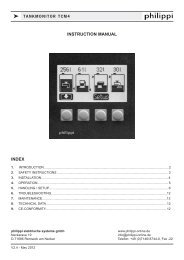
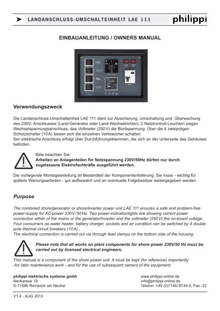
Verwendungszweck<br />
Die Landanschluss-Umschalteinheit LAE 111 dient zur Absicherung, Umschaltung und Überwachung<br />
des 230V- Anschlusses (Land-Generator oder Land-Wechselrichter). 2 Netzkontroll-Leuchten zeigen<br />
Wechselspannungsanschluss, das Voltmeter (250V) die Bordspannung. Über die 4 zweipoligen<br />
Schutzschalter (10A) lassen sich die einzelnen Verbraucher schalten.<br />
Der elektrische Anschluss erfolgt über Durchführungsklemmen, die sich an der Unterseite des Gehäuses<br />
befinden.<br />
Bitte beachten Sie:<br />
Arbeiten an Anlagenteilen für Netzspannung 230V/50Hz dürfen nur durch<br />
zugelassene Elektrofachkräfte ausgeführt werden.<br />
Die vorliegende Montageanleitung ist Bestandteil der Komponentenlieferung. Sie muss - wichtig für<br />
spätere Wartungsarbeiten - gut aufbewahrt und an eventuelle Folgebesitzer weitergegeben werden.<br />
Purpose<br />
The combined shore/generator or shore/inverter power unit LAE 111 ensures a safe and problem-free<br />
power-supply for AC-power 230V/50Hz. Two power-indicationlights are showing correct power<br />
connection either of the mains or the generator/inverter and the voltmeter (250V) the on-board voltage.<br />
Four consumers as water heater, battery charger, sockets and air condition can be switched by 4 double<br />
pole thermal circuit breakers (10 A) .<br />
The electrical connection is carried out via through lead clamps on the bottom side of the housing.<br />
Please note that all works on plant components for shore power 230V/50 Hz must be<br />
carried out by licensed electrical engineers.<br />
This manual is a component of the shore power unit. It must be kept (for reference) importantly:<br />
-for later maintenance work - and for the use of subsequent owners of the equipment.<br />
philippi elektrische systeme gmbh<br />
www.philippi-online.de<br />
Neckaraue 19<br />
info@philippi-online.de<br />
D-71686 Remseck am Neckar Telefon: +49 (0)7146/8744-0, Fax -22<br />
V1.4 - AUG 2013
k LANDANSCHLUSS-UMSCHALTEINHEIT LAE 111<br />
ANSCHLUSS LAE 111<br />
Kabelquerschnitt<br />
Kabelquerschnitt<br />
4 mm² für Netz-Zugang<br />
min. 1,5 mm² für Ausgang A, B, C und D<br />
Netz-Zugang Land<br />
230 Volt/50 Hz - Netzspannung Land<br />
Klemme 11 L1 (Phase - schwarz) Anschluss des Landstroms<br />
Klemme 12 N (Nullleiter - blau) Anschluss des Landstroms<br />
Klemme PE PE ( Schutzleiter - grün/gelb)<br />
Netz-Zugang Bordgerät 230 Volt/50 Hz - Netzspannung Generator/Wechselrichter<br />
Klemme 21 L1 (Phase - schwarz) Anschluss des Generators/Wechselrichters<br />
Klemme 22 N (Nullleiter - blau) Anschluss des Generators/Wechselrichters<br />
Klemme PE PE ( Schutzleiter - grün/gelb)<br />
Ausgang A<br />
geschaltet über Überstromschutzschalter “Hot Water” - 10A<br />
Klemme 31 L1 (Phase - schwarz) Anschluss des Boilers<br />
Klemme 32 N (Nullleiter - blau) Anschluss des Boilers<br />
Klemme PE PE ( Schutzleiter - grün/gelb)<br />
Ausgang B<br />
geschaltet über Überstromschutzschalter “Battery Charger” - 10A<br />
Klemme 41 L1 (Phase - schwarz) Anschluss des Ladegerätes<br />
Klemme 42 N (Nullleiter - blau) Anschluss des Ladegerätes<br />
Klemme PE PE ( Schutzleiter - grün/gelb)<br />
Ausgang C<br />
geschaltet über Überstromschutzschalter “Sockets” - 10A<br />
Klemme 51 L1 (Phase - schwarz) Anschluss der Steckdosen<br />
Klemme 52 N (Nullleiter - blau) Anschluss der Steckdosen<br />
Klemme PE PE ( Schutzleiter - grün/gelb)<br />
Ausgang D<br />
geschaltet über Überstromschutzschalter “Air Condition” - 10A<br />
Klemme 61 L1 (Phase - schwarz) Anschluss der Klimaanlage<br />
Klemme 62 N (Nullleiter - blau) Anschluss der Klimaanlage<br />
Klemme PE PE ( Schutzleiter - grün/gelb)<br />
alle Ausgänge sind über den Fehlerstromschutzschalter RCBo 25 A (30mA) abgesichert.<br />
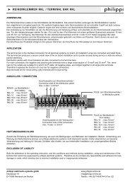
Rückansicht LAE 111<br />
PE 62 61 PE 52 51 PE 42 41 PE 32 31 PE 22 21 PE 12 11<br />
Air Condition<br />
min. 3 x 1,5 mm²<br />
Sockets<br />
min. 3 x 1,5 mm²<br />
Battery Charger<br />
min. 3 x 1,5 mm²<br />
Hot Water<br />
min. 3 x 1,5 mm²<br />
Generat./Wandler<br />
3 x 4 mm²<br />
Land<br />
3 x 4 mm²<br />
Seite 2 V1.4 - AUG 2013
k SHORE POWER SWITCH OVER UNIT LAE 111<br />
CONNECTION LAE 111<br />
Wire cross section<br />
Wire cross section<br />
4 mm² for power supply<br />
min. 1,5 mm² for outputs A, B, C and D<br />
Power supply mains 230 Volt/50 Hz - shore power<br />
clamp 11 L1 (life - black) Connection of shore power<br />
clamp 12 N (neutral - blue) Connection of shore power<br />
clamp PE PE (protective earth conductor - green/yellow)<br />
Power supply onboard unit 230 Volt/50 Hz - generator/inverter<br />
clamp 11 L1 (life - black) Connection of generator/inverter<br />
clamp 12 N (neutral - blue) Connection of generator/inverter<br />
clamp PE PE (protective earth conductor - green/yellow)<br />
Output A<br />
switched through thermal circuit breaker “Hot Water” - 10A<br />
clamp 21 L1 (life - black) Connection of the water heater<br />
clamp 22 N (neutral - blue) Connection of the water heater<br />
clamp PE PE (protective earth conductor - green/yellow)<br />
Output B<br />
switched through thermal circuit breaker “Battery Charger” - 10A<br />
clamp 31 L1 (life - black) Connection of the battery charger<br />
clamp 32 N (neutral - blue) Connection of the battery charger<br />
clamp PE PE (protective earth conductor - green/yellow)<br />
Output A<br />
switched through thermal circuit breaker “Sockets” - 10A<br />
clamp 21 L1 (life - black) Connection of the sockets<br />
clamp 22 N (neutral - blue) Connection of the sockets<br />
clamp PE PE (protective earth conductor - green/yellow)<br />
Output B<br />
switched through thermal circuit breaker “Air Condition” - 10A<br />
clamp 31 L1 (life - black) Connection of the air condition<br />
clamp 32 N (neutral - blue) Connection of the air condition<br />
clamp PE PE (protective earth conductor - green/yellow)<br />
all outputs are protected by a fault-current circuit breaker RCBo 25 A (30 mA)<br />
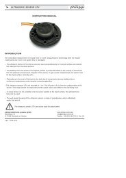
Rear View LAE 111<br />
PE 62 61 PE 52 51 PE 42 41 PE 32 31 PE 22 21 PE 12 11<br />
Air Condition<br />
min. 3 x 1,5 mm²<br />
Sockets<br />
min. 3 x 1,5 mm²<br />
Battery Charger<br />
min. 3 x 1,5 mm²<br />
Hot Water<br />
min. 3 x 1,5 mm²<br />
Generat./Inverter<br />
3 x 4 mm²<br />
Shore<br />
3 x 4 mm²<br />
V1.4 - AUG 2013 Page 3
k SHORE POWER SWITCH OVER UNIT LAE 111<br />
TECHNISCHE DATEN / TECHNICAL DATA<br />
LAE 111<br />
Versorgungsspannung 230 Volt / 50 Hz Wechselspannung<br />
Absicherung<br />
RCBo 25A, 30mA<br />
Ausgang A & B & C & D Überstromschutzschalter 10A; RCBO 30mA<br />
Abmessungen B 260 x H 185 x T 100<br />
Einbauausschnitt<br />
B 235 x H 160 (Mindesttiefe 97 mm)<br />
LAE 111<br />
Supply voltage<br />
230 Volt / 50 Hz AC-Voltage<br />
Protection<br />
RCBo 25A, 30mA<br />
Output A & B & C & D Thermal circuit breaker 10A; RCBO 30mA<br />
Dimensions W 260 x H 185 x D 100<br />
Installation dimensions W 235 x H 160 (minimum depth 97 mm)<br />
CE-KONFORMITÄTSERKLÄRUNG<br />
Dieses Produkt erfüllt die Anforderungen der EU - Richtlinien:<br />
2004/108/EG "Elektromagnetische Verträglichkeit"<br />
Störfestigkeit EN 61000-6-1<br />
Störaussendung EN 61000-6-3<br />
2006/95/EG "Elektrische Betriebsmittel zur Verwendung innerhalb bestimmter<br />
Spannungsgrenzen"<br />
Die Konformität des Gerätes mit den o.g. Richtinien wird durch das CE-Kennzeichen bestätigt.<br />
DECLARATION OF CONFORMITY<br />
This device fulfills the requirements of the European regulations:<br />
2004/108/EG “ElectroMagnetic Compatibilit”<br />
Immunity EN 61000-6-1<br />
Emission EN 61000-6-3<br />
2006/95/EG “Electrical equipment designed for use within certain voltage limits”<br />
The conformity to this regulations is certified by the CE - sign.<br />
ENTSORGUNGSHINWEISE / DISPOSAL NOTE<br />
Beachten Sie bei der Entsorgung dieses Gerätes die geltenden örtlichen Vorschriften und<br />
nutzen Sie die Sammeldienste/-stellen für Elektro-/Elektronik-Altgeräte.<br />
Please take care of your local directives on waste electrical and electronic equipment.<br />
Please use collection points for waste electrical and electronic equipment.<br />
Seite /Page 4 V1.4 - AUG 2013