AUTOMATIKLADER - Philippi
AUTOMATIKLADER - Philippi
AUTOMATIKLADER - Philippi
- No tags were found...

Create successful ePaper yourself
Turn your PDF publications into a flip-book with our unique Google optimized e-Paper software.
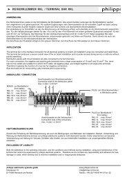
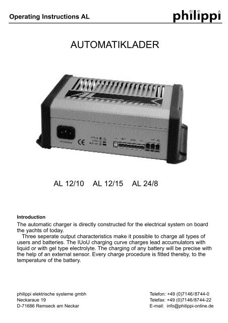
Operating Instructions AL4. InstallationThe charger is intended for the wall assembly. Over four fixing bolts the charger can be easily installed. Aassembly on the bottom is also permissible. Please ensure that chargers are installed where is sufficient aircirculation to cool the power electronics and transformer.Chargers should not be installed in the battery space nor a gasoline engine room nor where the fuel tanksare located, due to explosion hazard arising from gassing vapours (oxyhydrogen) of batteries or gasolinefumes. Please ensure that the chargers are properly fastened down mechanically.4.1 Electrical connection ACThe mains connection is made by theprovided mains cable with cold equipmentclutch and protective contact plug. Theprotective contact plug may not be cut off,but it must be present a protectivecontact socket as interface. It is recommended,to switch the charger over anexternal switch in the net inlet on and off.4.2 Electrical connection DCThe battery connection takes place onthe front at the plug-able clamp in accordancewith the diagram of connections.For a professional and reliable connectionthe ends of the load lines must be crimpedwith the suitable pigtails. To ensurea suitable connection, the screws of theclamps must be tightened with a slotted
Operating Instructions ALbolt turner 4,5mm and/or screwdrivers of size 2 (Pozidrive). If only one batterie (group) will be connected,then this is to be attached to exit +1. Further groups of batteries are attached at the exits +2It is to be made certain absolutely that the polarity of the battery is considered. Keep the wiring between batterycharger and the batteries as short as possible. Shift if possible no lines of recieving equipement parallelto the loading and main lines to avoid HF disturbances. Use as possible colored lines for battery cabling. Ifnot possible, mark the cables with colored insulating tape. The indicated minimum cross sections of a lineare to be kept absolutely.Charging current recom. fuse size Cable length 2m10 A 15 A 1,5 mm² 2,5 mm²15 A 20 A 2,5 mm² 4 mm²The plus load lines must be secured in the proximity of the batteries by suitable fuses or breakers. The fusesize should be appropriate for something over the nominal charging current of the battery charger. Examinethe wiring annually. To thin cables and/or loose connections can have dangerous overheatings at cables andinstallation to the consequence. Pay attention to firm connections, in order to avoid high transition resistances.4.3 Connection of the optional temperature sensorThe temperature sensor measures the temperature of the battery. It should beattached therefore at the exterior of the battery. It is sufficiently if this by meansof tape at the exterior of the battery is fixed. The housing of the temperaturesensor is electrically isolated. The electrical connection of the temperature sensorstakes place at the lower row of terminals on the front side of the charger.The cable length of the temperature sensor amounts to 2.8 m, if this should notbe sufficient it can be extended or shortened without limits. If no temperaturesensor is attached, then the charger works with the standard voltage levels,which correspond to a temperature of 20 °C.4.4 Connection of charging control (Optional: FB-P)External charging control (option) is left justified put in at the upper row of terminals on the front side of thecharger.terminal No. 1: white line (+ LED ye)terminal No. 2: brown line (+ LED gr)terminal No. 3: green line (- Minus)
Operating Instructions AL4.5 Connection of the display (option LCM)The connector of the external display LCM (option) is to put in right-justified at the upper roe of terminals onthe front side of the charger:Pin Nr. 3: screenPin Nr. 4: brown linePin Nr. 5: white linePin Nr. 6: green line4.6 DIP-switchesThe DIP switches are at the front side (not at AL 12/10),1 2 3 4 5 6 7 8Changes in the Dip switches may be made only with switched off charger !Dip-switch OFF ON1 liquid Gel / AGM2 +2 Service +2 StartFactory-installed all Dip switches are posed on ON.ONOFF(1) Gel.- / Liquid-BatteriesCharging voltage Gel / AGM: 14,4V/13,8 V, bzw. 28,8V/27,6V.Charging voltage liquid: 14,3 V/13,6 V bzw. 28,6V/27,2V.please find also chapter 4 (Charging)(2) Outlet +2With starter mode charge will done with with reduced tension (-0,7V).With service mode charge will be done with full output voltage such as outlet +1.
Operating Instructions AL5. OperationSwitch on:As soon as the charger is connected to the mains voltage, it goes into enterprise. By means of the IUoUcharacterisic with temperature compensation the charger can remain constant in enterprise, without damagingthe batteries.5.1 Control lampsTo monitor the charging progress and the operating condition 3 colored control lights are inserted in the frontof the charger. These indicate the following operating conditions of the charger.control lightred yellow greenOperating condition● ● Power supply mode●The batteries are charging (IU-Phase).●The batteries are fully charged and now the tickle charge is running.❍No battery is connected, short circuit, reversed connected or unloaded under3 V or. 6 V (24 V Unit).● ❍ The maximum charger temperature of 70 °C was exceeded. The chargerlimits the current, so that no further heating up takes place.● ❍ ❍ The batteries temperature run out of the range (-10 - 50 °C). The charging willbe stopped until the batterie temperature will be back in the range.● ● ● A temperature sensor ist short circuited. The charging willbe stopped until the short circuit is removed.● LED leuchtet❍ LED blinkt5.2 ChargingThe outlet +1 is the main exit, after the charge is primarilycontrolled. The batteries attached to outlet +1 arealways charged with a IUoU characteristic (except powersupply unit mode, then only IU characteristic curve). Furthergroups of batteries are attached at the outlets +2and +3, which can be set individually to service -oderstarter characteristic. The attached batteries are loadedwith the rated current up to reaching the gassing voltage.After reaching the gassing voltage the charging voltage iskept constant on this (absorption phase). Thereby the
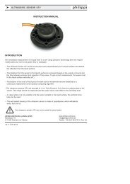
Operating Instructions ALcharging current sinks since the charging voltage is not any longer increased.After the absorption current is sunk under 50% of the nominal value the charging voltage still 4 hours held atthe gassing voltage around an optimal volume charge to reach. After this, the charging voltage is reduceddown the floating voltage, in order to compensate the self discharge of the batteries. Likewise to the batteryattached consumer is along-supplied by the battery charger.The gassing voltage of a lead-acid battery depends on thetemperature. By means of a temperature sensor the battery(environment) temperature is seized and those max. chargingvoltage automatically adapted. Thus during the chargingat different temperatures the gassings voltage of a lead-acidbattery is never exceeded. If no temperature sensor is attached,with the voltage levels one loads, which correspond toa temperature of 20°C.Temperaturabhängigkeit der Gasungsspannungeiner 12V-Blei-Gel-Batterie14,715 14,414,113,813,513,2-10 0 10 20 30 40 50Temperatur (°C)6. Important hints for the operation- Not used outlets have to be set to service battery use.- The battery (group) with the largest capacity/demand must be attached on outlet +1.- If only one group of batteries ist connected, then this is attached to the outlet +1.- The charger adapts to an input voltage of 120 V automatically. From the low input voltage audible noises inthe switch power pack result. Around these to reduce the charging current should be halved at the loadmonitor LCM or the Sleep mode be activated.- Is the equipment defectively must it directly to the manufacturer be sent in, repair attempts third lead due tothe complexity of the equipment not to success. Also an exchange of the safety devices is to be avoided tooomitted around a further damage of the equipment.- Due to the extensive output configuration of the 3 outlets small crosswise currents between the groups ofbatteries during the charging will appear. These are however harmless for the battery charger and the attachedbatteries.- Both gel and liquid acid batteries are connected, then we recommend the charge in the gel mode.- AGM batteries must be loaded in the gel mode.Ladespannung(V)
Operating Instructions AL7. Technical datasAutomatiklader AL12/10 AL 12/15 AL 24/8Input voltage / frequency180-264 VFull load consumption 1,2 A 1,7 A 1,7 AFull load consumption 280 VA 390 VA 390 VARated battery voltage 12 V 24 VOutput voltage @20°C Gel/AGM 14,4 V Gel/AGM 28,8 Vbulk / absorption Naß 14,3 V Naß 28,6 VOutput voltage @20°C Gel/AGM 13,8 V Gel/AGM 27,6 Vfloat Naß 13,6 V Naß 27.2 VCharge current (+/- 1A) 10 A 15 A 8 Arecommendedtotal batteries capacity 30- 100 Ah 50-150 Ah 25-80 AhCharacteristicIUoUTemperature range-10 °C / +40 °C, with following power reductionCoolingself coolingWeight1,2 kgProtectionDimensions BxTxH (mm)250x142x84mm8 Declaration of comformityManufacturer: philippi elektrische systemeAddress: Neckaraue 1971686 Remseck - GermanyHerewith declares that:the chargers are in conformity with the provision of the EC EMC directive 89/336/EECand amendments 92/31/EEC and 93/68/EEC.V1.0 - Feb 2006