k LAE 234 LGK - Philippi
k LAE 234 LGK - Philippi
k LAE 234 LGK - Philippi

You also want an ePaper? Increase the reach of your titles
YUMPU automatically turns print PDFs into web optimized ePapers that Google loves.
k <strong>LAE</strong> <strong>234</strong> <strong>LGK</strong><br />
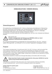
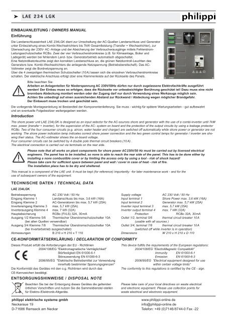
EINBAUANLEITUNG / OWNERS MANUAL<br />
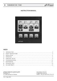
Einführung<br />
Die Landanschlusseinheit <strong>LAE</strong> <strong>234</strong><strong>LGK</strong> dient zur Umschaltung der AC-Quellen Landanschluss und Generator<br />
unter Einbeziehung eines Kombi-Wechselrichters bis 7kW Gesamtleistung (Transfer + Wechselrichter), zur<br />
Überwachung der 230V- AC-Anlage und der Absicherung der Verbraucherausgänge mittels Fehlerstrom-<br />
Leitungsschutzschalter RCBo. Zwei der vier Verbraucherstromkreise (z.B. für Klimaanlage, Boiler und<br />
Ladegerät) werden bei fehlendem Land- bzw. Generatorbetrieb automatisch abgeschaltet.<br />
Eine Netzindikatorleuchte zeigt den korrekten Landanschluss an, die grünen Netzkontroll-Leuchten des<br />
Generators bzw. Kombi-Wechselrichters die anliegende Netzspannung (Betriebsbereitschaft). Das AC-<br />
Voltmeter zeigt die Bordnetzspannung an.<br />
Über die 4 zweipoligen thermischen Schutzschalter (10A) lassen sich die einzelnen Verbraucherstromkreise<br />
schalten. Der elektrische Anschluss erfolgt über eine Klemmenleiste auf der Rückseite des Panels.<br />
Bitte beachten Sie:<br />
Arbeiten an Anlagenteilen für Niederspannung AC 230V/50Hz dürfen nur durch zugelassene Elektrofachkräfte ausgeführt<br />
werden! Der Einbau muss so erfolgen, dass die Rückseite vor unbeabsichtigter Berührung geschützt ist! Dazu muss eine nicht<br />
brennbare Abdeckung montiert werden oder der Zugang darf nur durch Verwendung eines Werkzeugs möglich sein.<br />
Achten Sie unbedingt auf einen ausreichenden Abstand zur Rückwand / Abdeckung wegen möglicher Brandgefahr.<br />
Der Einbauort muss trocken und geschützt sein.<br />
Die vorliegende Montageanleitung ist Bestandteil der Komponentenlieferung. Sie muss - wichtig für spätere Wartungsarbeiten - gut aufbewahrt<br />
und an eventuelle Folgebesitzer weitergegeben werden.<br />
Introduction<br />
The shore power unit <strong>LAE</strong> <strong>234</strong><strong>LGK</strong> is designed as an input selector for the AC-sources shore and generator with the use of a combi-inverter until 7kW<br />
max. power (transfer + inverter), for the supervision of the AC- system on board and the protection of the output circuits by using a leakage protector<br />
RCBo. Two of the four consumer circuits (e.g. aircon, water heater and charger) are switched off automatically while shore power or generator are not<br />
working. The shore power indication lamp indicates correct shore power connection and the two green control lamps for generator / inverter are showing<br />
their status. The AC-voltmeter shows the on-board voltage.<br />
Four consumer circuits can be switched by 4 double pole thermal circuit breakers (10 A) .<br />
The electrical connection is carried out via terminals on the rear side.<br />
Please note that all works on plant components for shore power AC230V/50 Hz must be carried out by licensed electrical<br />
engineers. The panel has to be installed, so none is able to reach the rear side of the panel. This has to be done either by<br />
installing a none combustible cover or by limiting the access only by using a tool - risk of shock hazard!<br />
Please take care for sufficient space between panel and wall / cover in case of heat - risk of fire.<br />
The installation place has to be dry and sheltered.<br />
This manual is a component of the <strong>LAE</strong> unit. It must be kept (for reference) importantly: -for later maintenance work - and for the<br />
use of subsequent owners of the equipment.<br />
TECHNISCHE DATEN / TECHNICAL DATA<br />
<strong>LAE</strong> <strong>234</strong><strong>LGK</strong><br />
Betriebsspannung AC 230 Volt / 50 Hz Supply voltage AC 230 Volt / 50 Hz<br />
Eingang Klemme 1 Landanschluss bis max. 3,6 kW (16A) Input terminal 1 Shore Power max. 3,6 kW (16A)<br />
Eingang Klemme 2 AC-Generatoren bis max. 5,7 kW (25A) Input terminal 2 Generator max. 5,7 kW (25A)<br />
Invertereingang Klemme 3 max. 5,7 kW (25A) Inverter input terminal 3 max. 5,7 kW (25A)<br />
Inverterausgang Klemme 4 max. 7 kW (32A) Inverter output terminal 4 max. 7 kW (32A)<br />
Hauptabsicherung RCBo (FI/LS) 32A, 30mA Protection RCBo 32A, 30mA<br />
Ausgang 1/2 Klemme 5/6 Thermischer Überstromschutzschalter 10A Outlet 1/2, terminal 5/6 thermal circuit breaker 10A<br />
(bei allen Quellen verwendbar) (usable with all sources )<br />
Ausgang 3/4 Klemme 7/8 Thermischer Überstromschutzschalter 10A Outlet 3/4, terminal 7/8 thermal circuit breaker 10A<br />
(bei Inverterbetrieb ausgeschaltet)<br />
(switched off while inverter is in operation)<br />
Abmessungen B 210 x H 210 x T 110 Dimensions W 210 x H 210 x D 110<br />
CE-KONFORMITÄTSERKLÄRUNG / DECLARATION OF CONFORMITY<br />
Dieses Produkt erfüllt die Anforderungen der EU - Richtlinien<br />
This device fulfills the requirements of the European regulations:<br />
2004/108/EG "Elektromagnetische Verträglichkeit"<br />
2004/108/EG “ElectroMagnetic Compatibilit”<br />
Störfestigkeit EN 61000-6-1 Immunity EN 61000-6-1<br />
Störaussendung EN 61000-6-3 Emission EN 61000-6-3<br />
2006/95/EG "Elektrische Betriebsmittel zur Verwendung<br />
2006/95/EG “Electrical equipment designed for use<br />
innerhalb bestimmter Spannungsgrenzen"<br />
within certain voltage limits”<br />
Die Konformität des Gerätes mit den o.g. Richtinien wird durch das<br />
The conformity to this regulations is certified by the CE - sign.<br />
CE-Kennzeichen bestätigt.<br />
ENTSORGUNGSHINWEISE / DISPOSAL NOTE<br />
Beachten Sie bei der Entsorgung dieses Gerätes die geltenden<br />
örtlichen Vorschriften und nutzen Sie die Sammeldienste/-stellen<br />
für Elektro-/Elektronik-Altgeräte.<br />
Please take care of your local directives on waste electrical<br />
and electronic equipment. Please use collection points for<br />
waste electrical and electronic equipment.<br />
philippi elektrische systeme gmbh<br />
www.philippi-online.de<br />
Neckaraue 19<br />
info@philippi-online.de<br />
D-71686 Remseck am Neckar Telefon: +49 (0)7146/8744-0 Fax -22
k <strong>LAE</strong> <strong>234</strong> <strong>LGK</strong><br />
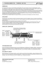
ANSCHLUSSPLAN:<br />
WIRING DIAGRAM:<br />
4mm²<br />
Relais für Verbraucherausgrenzung Bordnetz 3 & 4<br />
bei fehlendem Landanschluss bzw. Generatorbetrieb<br />
Solenoid to switch off consumer outlets 3 & 4<br />
while shore power or generator are not in use.<br />
1 3<br />
A1<br />
2 4<br />
S 2<br />
A2<br />
4mm²<br />
0,75mm²<br />
0,75mm²<br />
4mm²<br />
F1: RCBo<br />
F 5 F 4<br />
F 3<br />
F 2<br />
3 2 A<br />
3 0 m A<br />
2<br />
6<br />
S 1 ( 2 5 A )<br />
( C A 1 6 A 2 11 )<br />
L 0 G<br />
3 1 7 5<br />
6 m m ²<br />
4 m m ²<br />
2 , 5 m m ²<br />
4 m m ²<br />
8<br />
L<br />
8<br />
N<br />
P E<br />
7<br />
L<br />
7<br />
N<br />
P E<br />
6<br />
L<br />
6<br />
N<br />
P E<br />
5<br />
L<br />
5<br />
N<br />
P E<br />
4 4 3 3<br />
L N P E L N<br />
P E<br />
1<br />
L<br />
1<br />
N<br />
P E<br />
2<br />
L<br />
2<br />
N<br />
P E<br />
max. 10A max. 10A max. 10A max. 10A max. 32A max. 25A<br />
Bordnetz 4<br />
AC OUT<br />
OUTLET 4<br />
Bordnetz 3<br />
AC OUT<br />
OUTLET 3<br />
( 1 0 A ) ( 1 0 A )<br />
Verbraucher (z.B. Boiler<br />
oder Klimaanlage), die<br />
bei Inverterbetrieb ausgeschaltet<br />
bleiben.<br />
Consumers (e.g.Water<br />
Heater, Aircon), which<br />
shall be switched off<br />
while the inverter is<br />
in operation.<br />
Bordnetz 2<br />
AC OUT<br />
OUTLET 2<br />
Bordnetz 1<br />
AC OUT<br />
OUTLET 1<br />
( 1 0 A ) ( 1 0 A )<br />
Verbraucher, die immer<br />
(bei allen Quellen) verwendet<br />
werden dürfen.<br />
Consumers, which can<br />
be operated with all<br />
sources.<br />
Beim Einbau muss die Europäische Norm<br />
EN ISO 13297 beachtet werden.<br />
Installation: take care to follow the European<br />
regulation ISO 13297.<br />
MCB-2P<br />
6 m m ²<br />
4 m m ²<br />
M C B MCB-2P M C B<br />
max. 2 p 116A<br />
6 A max. 2 p 225A<br />
5 A<br />
AC OUT<br />
AC IN<br />
KOMBI-INVERTER<br />
C o m b i I n v e r t e r<br />
COMBI INVERTER<br />
LAND I n p u t<br />
S h o r e<br />
AC IN<br />
SHORE<br />
2 , 5 m m ²<br />
4 m m ²<br />
GENERATOR<br />
I n p u t<br />
G e n e r a t o r<br />
AC IN<br />
GENERATOR<br />
Netzindikatorleuchte Landeingang:<br />
Grün: Korrekt<br />
Rot: Verpolt<br />
Blinkend: Fehler (Schutzleiter PE nicht verbunden)<br />
Shore Power Indication Lamp AC IN Shore:<br />
Green: OK<br />
Red: Reverse polarity<br />
Flashing: Error (protective earth conducor not connected)<br />
philippi elektrische systeme gmbh<br />
www.philippi-online.de<br />
Neckaraue 19<br />
info@philippi-online.de<br />
D-71686 Remseck am Neckar Telefon: +49 (0)7146/8744-0 Fax -22