INSTRUCTION MANUAL - Philippi
INSTRUCTION MANUAL - Philippi
INSTRUCTION MANUAL - Philippi

You also want an ePaper? Increase the reach of your titles
YUMPU automatically turns print PDFs into web optimized ePapers that Google loves.
k ISOLATING TRANSFORMER RTR<br />
<strong>INSTRUCTION</strong> <strong>MANUAL</strong><br />
INDEX<br />
1. INTRODUCTION..........................................................................................................................2<br />
2. SAFETY <strong>INSTRUCTION</strong>S .............................................................................................................3<br />
3. INSTALLATION..............................................................................................................................4<br />
4. CE-CONFORMITY.........................................................................................................................6<br />
5. TECHNICAL DATA.................................................................................................................. ......7<br />
philippi elektrische systeme gmbh<br />
www. philippi-online.de<br />
Neckaraue 19<br />
info@philippi-online.de<br />
D-71686 Remseck am Neckar Telefon: +49 (0)7146/8744-0, Fax -22<br />
V2.3 - April 2012
k ISOLATING TRANSFORMER RTR<br />
1. INTRODUCTION<br />
Dear customer,<br />
Thank you for buying the isolating transformer RTR. A toroidal transformer with a housing by salt water<br />
resistant aluminium with a plastic coating as surface protection allows a galvanic isolation of the shore<br />
power supply and adaptation of the input- respectively output voltage of your on board network.<br />
You can use the isolating transformer for:<br />
a) galvanic isolation of the on board network; recommended for boats with metal hull<br />
b) operating of 115V devices by a shore power supply of 230V, if you`ve bought an american vessel<br />
c) operating of 230 V devices by a shore power supply of 115V, for example for use of european devices<br />
on the american continent<br />
Due to the inrush current limiter there is no danger of blowing the shore fusing when switching on.<br />
1.1. PURPOSE<br />
The isolating transformer of the RTR series were designed for the use on yachts or camper vans and<br />
must be used in an enclosed environment which is protected against rain, moisture, dust and<br />
condensation. Don`t use isolating transformers in places where there could be danger of explosion by<br />
gas or dust.<br />
1.4. WARRANTY<br />
philippi elektrische systeme gmbh grants a two year limited and not transferable warranty for the first<br />
buyer of this equipment, commencing on the date of purchase and covers defects in manufacturing,<br />
parts and materials.<br />
Production or material defects will be corrected without costs if:<br />
x the equipment will be send to us at the expense of the sender<br />
x enclose the receipt (copy) of purchase<br />
x the equipment was treated in the intended use<br />
x no strange spare parts were built in or external effects happened<br />
Not included in the warranty are damages from:<br />
x overvoltage in the inputs or reverse polarity<br />
x entered liquids in the device or oxydation through condensation<br />
x lightning<br />
Not under warranty are follow-up costs and normal wear and tear.<br />
Page 2 V2.3 - April 2012
k ISOLATING TRANSFORMER RTR<br />
In case of warranty there must be a specification of the defect. A detailed description of<br />
the defect will ease and speed up the repair.<br />
Please note that we cannot accept carriage forward deliveries.<br />
1.3. EXCLUSION OF LIABILITY<br />
Both the adherence to the operating instruction, and the conditions and methods during installation,<br />
using and maintenance of the isolating transformers cannot be supervised by philippi electrical systems.<br />
Therefore we do not take any responsibility for loss, damage or costs, which develop due to incorrect<br />
installation and/or inappropriate enterprise.<br />
1.4. QUALITY MANAGEMENT<br />
During the process of manufacturing all devices pass several checks, controls and tests. Production,<br />
controls and tests are due to given protocols. Each RTR has its own serial number. Please do not<br />
remove this label.<br />
The assembly and testing of all RTR devices is carried out completely in our company at Remseck am<br />
Neckar.<br />
2. SAFETY REFERENCES<br />
x unautorised change to the equipment will invalidate the CE sign<br />
x the installation of the isolating transformer may be made only by electrical specialists.<br />
x while in use the cover of the RTR has not to be opened.<br />
x an obstruction of the ventilation cause an overheating of the device and can produce a breakdown.<br />
Do not cover the vents openings.<br />
The assembly and operating instruction is a component of the RTR package. It must be<br />
kept (for reference). Importantly: - for later maintenance work - and for the use of subsequent<br />
owners of the equipment.<br />
V2.3 - April 2012 Page 3
k ISOLATING TRANSFORMER RTR<br />
3. INSTALLATION<br />
The isolating transformers are designed for installation on a wall or the floor. It will be fixed by four<br />
fastening screws. Please install the isolation transformer in a well ventilated area..<br />
For installation a space in a locker or engine room of a diesel engine would suit. The isolating transformer<br />
has not to be installed in an engine room of a petrol engine, a battery locker and not in the<br />
neighbourhood of petrol tanks ( danger of explosion).<br />
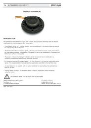
For installation firstly the top cover must be removed. The cover is fixed by four M4 - crosshead-screws<br />
on the top of the device. There are four holes at the bottom of the device for the mounting. The four<br />
transportation locking screws have to be removed. After that the transformer can be screwed through<br />
these holes to the wall or floor. There are also four higher-laying screws - they are for fixation of the<br />
transformer to the housing - please don`t remove them.<br />
The compression couplings have to be fixed on the front side and the input and output wires have to be<br />
passed through.<br />
Demounting the four transportation locking screws:<br />
compression -<br />
couplings<br />
The isolating transformer will be fixed through this four holes on the bottom of the device.<br />
Please pay attention, that the transformer has to be mounted electrically isolated<br />
in case of metal hulls ! (f.e. on a wooden plate)<br />
The fixing screws must be isolated from the hull too!<br />
Page 4 V2.3 - April 2012
k ISOLATING TRANSFORMER RTR<br />
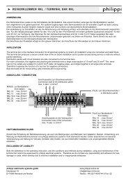
3.1 ELECTRICAL CONNECTION<br />
Connection Diagram:<br />
The input wires have to be connected to:<br />
L1 / N - MCB L1 / N<br />
PE - green/yellow terminal on the right hand side<br />
of the MCB<br />
The output wires have to be connected to:<br />
L1 - terminal L1<br />
N - terminal N<br />
PE - terminal PE<br />
The protective earth conductor at the output is<br />
separated to the shore power supply and connected to<br />
the neutral wire internally.<br />
For safety reasons there must be a RCBo - leakage<br />
protector installed on the output (f.e. a LAE 220).<br />
The nominal power of the external leakage protector<br />
RCBo has to match the output current of the isolating<br />
transformer ( see Technical Data).<br />
While in use both controllights are on:<br />
right: input winding<br />
left: output winding<br />
external:<br />
Input<br />
(Shore)<br />
Inrush current limiter<br />
Output<br />
(on board system)<br />
ACon<br />
board system<br />
Isolating transformer<br />
If you have a transformer with input switch over 115V / 230V please take care before<br />
switching on, that the selector switch is not in ”Zero”-position. That the electronic soft start<br />
works it has to be switched to the correlating input power. Otherwise maybe your shore<br />
power protection blows.<br />
V2.3 - April 2012 Page 5
k ISOLATING TRANSFORMER RTR<br />
6. CE-CONFORMITY<br />
philippi elektrische systeme gmbh<br />
Neckaraue 19<br />
71686 Remseck am Neckar<br />
Deutschland<br />
certifies herewith, that the products:<br />
Isolating transformers<br />
RTR 25 x/x<br />
RTR 36 x/x<br />
fulfills the requirements of the European Regulation:<br />
Low Voltage Directive 2006 / 95 / EG<br />
VDE 0570<br />
Following harmonised standards were implemented:<br />
Safety: EN 61558-2-1 : 2007<br />
EN 61558-2-4 : 1997<br />
Remseck, July 2009<br />
Dipl.-Ing. Michael Kögel<br />
general manager philippi<br />
Page 6 V2.3 - April 2012
k ISOLATING TRANSFORMER RTR<br />
7. TECHNICAL DATA<br />
Isolating transformer RTR 25-230//230 RTR 25-115//230 RTR 25-230//115 RTR 25 115/230//230<br />
Input voltage 230 V 115 V 230 V 115 V or 230 V over switch<br />
Output voltage 230 V / 10,8 A 230 V / 10,8 A 115 V / 21,7 A 230 V / 10,8 A<br />
Nominal power 2500 W 2500 W 2500 W 2500 W<br />
Weight 21 kg 21 kg 21 kg 21,5 kg<br />
Isolating transformer RTR 36-230//230 RTR 36-115//230 RTR 36-230//115 RTR 36 115/230//230<br />
Input voltage 230 V 115 V 230 V 115 V or 230 V over switch<br />
Output voltage 230 V / 15,6 A 230 V / 15,6 A 115 V / 31,3 A 230 V / 15,6 A<br />
Nominal power 3600 W 3600 W 3600 W 3600 W<br />
Weight 27 kg 27 kg 27 kg 27,5 kg<br />
Temperature range -10 °C / +40 °C,<br />
Protection IP 20<br />
Dimensions WxDxH (mm) 410 x 290 x 170<br />
All isolating transformers are equipped as standard by a professional electronic soft start and inrush current limiting ESB.