INSTRUCTION MANUAL INDEX - Philippi
INSTRUCTION MANUAL INDEX - Philippi
INSTRUCTION MANUAL INDEX - Philippi

You also want an ePaper? Increase the reach of your titles
YUMPU automatically turns print PDFs into web optimized ePapers that Google loves.
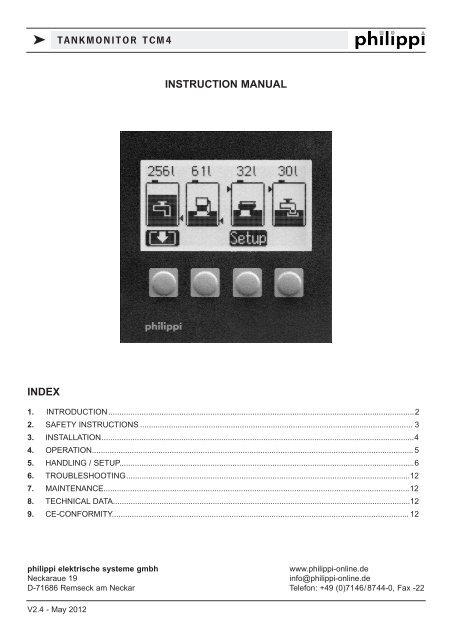
k TANKMONITOR TCM4<strong>INSTRUCTION</strong> <strong>MANUAL</strong><strong>INDEX</strong>1. INTRODUCTION..........................................................................................................................................22. SAFETY <strong>INSTRUCTION</strong>S ........................................................................................................................... 33. INSTALLATION.............................................................................................................................................44. OPERATION................................................................................................................................................. 55. HANDLING / SETUP.....................................................................................................................................66. TROUBLESHOOTING................................................................................................................................127. MAINTENANCE..........................................................................................................................................128. TECHNICAL DATA......................................................................................................................................129. CE-CONFORMITY...................................................................................................................................... 12philippi elektrische systeme gmbhwww.philippi-online.deNeckaraue 19info@philippi-online.deD-71686 Remseck am Neckar Telefon: +49 (0)7146/8744-0, Fax -22V2.4 - May 2012
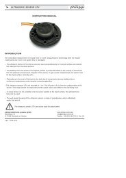
k TANKMONITOR TCM41. INTRODUCTIONDear customer,thank you for buying the tankmonitor TCM 4. This digital unit is state of the art in tank monitoringOn the large, illuminated display you can read:x the actual filling level of up to four tanksYou have the possibility of:x adjusting an alarm threshold (full or empty alarm)The tank levels are shown as a bar and in % or litres.The TCM 4 is easy to operate and well readable. You have a quick overview of up to four tank levels.For level-sensoring we recommend the sensors of our TGT / TGW - series, the ultrasonic sensors UTV andthe fresh water flow sensor DFS. These sensors are not part of the purchased parts package.Sensors of other manufacturers can be connected as well; depending on the type you may need a hardwareadaption at our company.In the SETUP- menu the display will be configurated to the connected sensors. Also you have the possibilityto adjust the tankmonitor to your given tank - geometry to show the real tank filling level correctly.Please note: only when using the flow sensors DFS the shown display of litres is correct, because it measuresthe flowed litres. If you`re using other sensors, the TCM calculates the remaining tank capacity bythe tank volume and the actual level. Depending on the accuracy of the sensors it cannot be litre-correct.EXTENDED ADJUSTMENT POSSIBILITIES starting from software 2A - May 2010:the tank depth can be adjusted to the centimetre by using ultrasonic sensors UTV40 orUTV80. If you`re using a distance ring to balance the off zone of the sensors, you cancompensate this value too! (please see page 9).Please, read the Instruction Manual carefully and follow all instructions before putting theequipment in operation.1.1. PURPOSEThe tankmonitors of the TCM-series can only be used with suitable tank sensors for low voltage purposesDC 10-30V. They were designed for the use on yachts or camper vans and must be used in an enclosedenvironment which is protected against rain, moisture, dust and condensation.Don`t use the TCM tankmonitors in places where there could be danger of explosion by gas or dust.1.2.CONTENTx Tankmonitor TCM 4x Plug-in clampx This Instruction Manual1.3. ACCESSORIES (TO BE ORDERED SEPARATELY)x Flow sensor for fresh water DFS Ord.-Nr.: 7 0003 0304x Tank sensor TGT / TGW 200-800 Ord.-Nr.: 6 6011 7xxxx Ultrasonic tank sensor UTV 20-80 Ord.-Nr.: 7 0219 35xxPage 2 V2.4 - May 2012
k TANKMONITOR TCM41.4. WARRANTYphilippi elektrische systeme gmbh grants a two year limited and not transferable warranty for the first buyer ofthis equipment, commencing on the date of purchase and covers defects in manufacturing, parts and materials.Production or material defects will be corrected without costs if:x the equipment will be send to us at the expense of the senderx enclose the receipt (copy) of purchasex the equipment was treated in the intended usex no strange spare parts were built in or external effects happenedNot included in the warranty are damages from:x overvoltage in the inputs or reverse polarityx entered liquids in the device or oxydation through condensationx lightningNot under warranty are follow-up costs and normal wear and tear.In case of warranty there must be a specification of the defect. A detailed description of thedefect will ease and speed up the repair.Please note that we cannot accept carriage forward deliveries.1.5. EXCLUSION OF LIABILITYBoth the adherence to the operating instruction, and the conditions and methods during installation, usingand maintenance of the TCM cannot be supervised by philippi electrical systems. Therefore we do not takeany responsibility for loss, damage or costs, which develop due to incorrect installation and/orinappropriate enterprise.1.6. QUALITY MANAGEMENTDuring the process of manufacturing all devices pass several checks, controls and tests. Production, controlsand tests are due to given protocols. Each TCM has its own serial number. Please do not remove this label.The assembly and testing of all TCM devices is carried out completely in our company at Remseck am Neckar.2. SAFETY REFERENCESx unautorised change to the equipment will invalidate the CE signx the installation of the TCM may be made only by electrical specialists.x Important! Pay attention to the correct polarity of the batteries!The assembly and operating instruction is a component of the TCM package. It must be kept(for reference). Importantly: - for later maintenance work - and for the use of subsequent ownersof the equipment.V2.4 - May 2012 Page 3
k TANKMONITOR TCM43.3. INSTALLATION AND CONNECTIONPlease install the TCM in a visible place, so that it can be read off at any time. The necessary installationcutout is 88 x 88mm, the necessary minimum depth is 40mm.The TCM supervises up to four tanks at the same time. If you have less sensors, start connecting the firstsensor at terminal TG 1 ( if you`re using two, connect them to TG 1 and TG 2 and so on)You can use both passive (resistance) and active (ultrasonic) sensors at the same time. For theconnection have a look at the connection diagramms.The flow sensor DFS has to be connected to terminal TG1 (if you`re using 2 flow sensors DFS,terminal TG1 and TG2)!If you want to use tank sensors with an output of 4-20mA or 0-10V you need a hardware-adaption atour company. Please ask.The power supply of the TCM is either directly from the battery or over a power distribution panel. Use a cable1,5mm² cross section which has to be fused (1A).The display is lit when you press a button or you can connect the terminal “Light” to a switch and switch iton/off manually.TG 4TG 3TG 2TG 1GND -DFS +UTV +12/24VGND -LightConnection of ultrasonic sensor UTV or over active sensors:ATTENTION:If the power supply of an ultrasonic sensor isconnected directly to the on board DC system,not through the tankmonitor, this connectionwire has to be fused by an 1A fuse!TG 4TG 3TG 2TG 1GND -DFS +UTV +12/24VGND -LightPage 4 V2.4 - May 2012
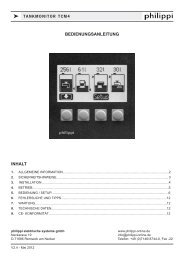
k TANKMONITOR TCM4Connection of passive (resistance) sensors like TGT /TGW and other:Connection of flow sensors DFS:TG 4TG 3TG 2TG 1GND -DFS +UTV +12/24VGND -LightTG 4TG 3TG 2TG 1GND -DFS +UTV +12/24VGND -Light(2.DFS)4. OPERATIONThe display shows the tank levels automatically after switching on.In the SETUP-menu you can adjust each tank-display individually to the medium (fuel, water...), to the type ofsensor used, to the compensation value for the tank-geometry and the alarm-threshold. In case of a power supplybreakdown all of these adjustments are saved and immediately available after switching on.The tank levels are measured each 5 s. The measured levels are shown in a bar diagram and additonallyeither in litres, in percent or without further indication. This can be adjusted in the SETUP-menu.If the indication over a tank is “----”, the measured value of the related tank is out of an expected value or thereis no sensor connected.If an alarm threshold for a tank is set up , this threshold is shown by a little triangle on the side of the bar.So you have a quick overview if the tank level is inside of the correct range.If the threshold is over 50%, the full -alarm is on, i.e. a filling level over the threshold set off the alarm.If the threshold is below 50% the empty - alarm is on, i.e. a filling level below the threshold sets off the alarm.In case of an alarm the related tank symbol is blinking and a buzzing signal is sounding for the preset time.The alarm can be acknowledged by you when pressing a buttonTo reduce the current consumption when using ultrasonic sensors (ca. 50mA / sensor), you can choose thePowersave Mode. Please note: when using the Powersave mode, the alarm is deactivated too!In the Powersave mode the measurement is carried out every 30 min. (11,5-13V) and every 2 hours(below 11,5V). The Powersave mode is activated automatically if the supply voltage goes below 11,5V to savethe batteries life. Under 10V no measurement takes place.In 24V- operation double values are applying.V2.4 - May 2012 Page 5
k TANKMONITOR TCM45. HANDLINGWhen pressing the push buttons the display light is lit during 60 s. If you connect the terminal “Light” to thepower supply via the power distribution panel the light can be activated manually.The alarm can be acknowledged by pressing a button.Following actions are activated by pressing:Button 1 Button 2 Button 3 Button 4Button 1 Long pressing (3s) Tank is being filled up in 5% steps until the maximumvalue (Only if tank1: Tanktype 40 -Flow sensor DFS)Button 2 Long pressing (3s) Tank is being filled up in 5% steps until the maximumvalue (Only if tank1: Tanktype 40 -Flow sensor DFS)Button 3 Short pressing (2s) “SETUP”- menu available; when the display is blinking,release the buttonLong pressing (5s) Setup-menu is locked / unlockedButton 4no function5.1. SETUPIn the SETUP-menu all adjustments can be changed:Following is the key function:Arrow:Plus:Minus:Return:selection of the line to be modifiedincrease the valuedecrease the valuesave the values and return to thetank displayPage 6 V2.4 - May 2012
k TANKMONITOR TCM4GLOBAL SETUP1. Display a) Display of the remaining tank capacity in litres (l)b) Display of the remaining tank capacity in percentage (%)c) No numerical display of the remaining tank capacity2.Amount of tanksAmount of the displayed tanks (1 - 4 tanks)3.Tank X Menuindividual adjustment of each tank:Capacity in litres, tanktype, Compensation-value, alarm - threshold andalarm - duration4. Language Language for the SETUP-menu. Available are following languages:German / English / French / Italian / Spanish5. Contrast Display contrast attitude + = dimmer, - = brighter6. Powersave Mode 1 = on, 0 = offThe inverted line can be changed.ADJUSTMENTS OF THE TANK DISPLAY:You get into the choosen tank menu by pressing the button 3 (arrow to the right):in the tank menu you can adjust the tank type (e.g. water, fuel, waste and the type of the sensor), thecapacity, the compensation-value (adjustment of the tank-geometry), the alarm-threshold and duration.Also you have the possibility to preset the ohm-values for 0%, 50% and 100% if your sensor has another rangeof resistance than 5 - 180 or 240 - 33 ohm (tank type 25 -29).V2.4 - May 2012 Page 7
k TANKMONITOR TCM4INDIVIDUAL TANK SETTINGS IN THE TANK MENU:CAPACITY OF THE TANKBy pressing the +/- - button you can adjust the capacity of the tank. The capacity is displayed in litres.TANK TYPE (Tank 1-4)By choosing the type of tank you`re defining both the desired display symbol and the type of a given sensor.There are 5 different tank symbols to choose of:Fresh Water Fuel Waste Water Grey-water GasTank type Sensor Measurement range Attention0 1 2 3 -4 philippi TRG 6 levels (6..190 Ohm)5 6 7 8 9 philippi TGT / TGW 5..180 Ohm10 11 12 13 14 philippi UTV 0,5..2,5V15 16 17 18 19 0...10 V Hardware adjustment!20 21 22 23 24 240...33 Ohm UTR not possible!A) 25 26 27 28 29 free adjustment of resistance range30 31 32 33 34 5 Stab Büschelgeber 4 Stufen AuxiliaryhardwarePB43!B) 35 36 37 38 39 philippi UTV 40/UTV 80 0,5..2,5VC) 40 Flow sensor DFS former: tank type 354...20mA possible by: Hardware adjustment!Incorrect display information can occur due to not compatible parts. Please ensure that the tank type matchesthe sensor. In former models the tank type of the flow sensor DFS was 35.A) FREE ADJUSTMENT OF THE RESISTANCE RANGE OF THE SENSOR:(TANK TYPE 25/ 26/ 27/ 28/29)Does your sensor have a characteristic line which doesn`t exist in the SETUP? In this mode you can adjust thedisplay to your sensor!Sensors: this mode can only be used in connection with resistance-sensors, not in connection withactive / capacitive sensors!The resistance-values for 3 levels (0%, 50%, 100%) have to beentered. First you have to measure the resistance of your sensorwhen the tank level is empty, half-full and full by using an ohmmeter.You have to enter these values in the submenu of theaccording tank at 0%, 50% and 100%.Page 8 V2.4 - May 2012
k TANKMONITOR TCM4B) ADJUSTMENT OF THE TANK DEPTH + DISTANCE RING(TANK TYPE 35 / 36 / 37 / 38 / 39 )You need the following ultrasonic sensor:- tank depth plus distance ring equal or less than 40 cm: UTV40- tank depth plus distance ring greater than 40 cm: UTV80 (max. depth measurable : 80 cm)The depth of each tank can be adjusted to the centimetre in the SETUP-menu.After entry of the tank type 35 - 39 the displayshows the depth 40 cm:Now you can adjust the depth by pressingthe - / + buttonsIs the depth of the tank greater than 40 cm, you have touse an UTV80. The TCM4 is showing that automatically:To balance the off zone of the ultrasonic sensor (the range which is not measurable between sensor and liquidsurface - 50 mm) you can use a distance ring UTS 25 or UTS 50.If you`re using such a distance ring you can entry this distance too.If the tank depth plus the distance ring is equal or less than 40 cm you need an UTV 40; greater than 40 cm anUTV 80. The TCM4 shows the type of UTV- sensor required automatically.ATTENTION! If the total of tank depth and distance ring is greater than 40 cm, you have to usean UTV 80! (f.e. tank depth is 37 cm and distance ring is 5 cm = total depth is 42 cm)You can use only ultrasonic sensors UTV40 or UTV80!V2.4 - May 2012 Page 9
k TANKMONITOR TCM4C) TANK TYPE 40 - DFS (former software: tank type 35)If the tank type 40 (flow sensor DFS) is preset for tank 1 or 2, the following symbol is shown in thebasic display:after filling-up of the tank you can fill-up the shown content according to the filling in stepsof 5% by long-pressing (ca. 5s) of the button.If there`s water flowing through the flow sensor DFS and the tank is filled, this is shownby a rotating bar. If the tank is empty, the bar doesn`t rotate.ADJUSTING THE ALARMYou can adjust the alarm threshold for each tank separately.Alarm duration 0 s Alarm off1... 600 s Alarm duration 1... 600 seconds601 s Alarm open end, until it will be acknowlegded by pressing a buttonor if the measured value has changed so that the alarm is cancelled.Alarm level 0 % Alarm off1..50 % Empty-alarm: if the level falls below the adjusted threshold thealarm will be activated. The activation is delayed by 15s.51... 99 % Full-alarm: if the level rises above the adjusted threshold the alarmwill be activated. The activation is delayed by 15s.POWERSAVE- MODE (PS)The Powersave mode (PS) is only for the use with ultrasonic sensors UTV, or other active sensors, becausethese sensors have a power consumption of ca. 50 mA of each sensor.If the Powersave mode is activated in the SETUP, there`s thesign “PS” down to the right.ATTENTION!In the Powersave mode the alarm is switched off!Page 10 V2.4 - May 2012
k TANKMONITOR TCM4In the Powersave mode the measurement takes place in dependence of the supply voltage:Above 13V the Powersave mode is switched off automatically. Below 11,5V automatically switched on.If the supply-voltage is between 11,5 - 13V a measuring cycle takes place every 30 minutes;if the supply voltage is below 11,5V a measuring cycle takes place every 2 hours.A measuring cycle lasts 5 minutes, thereby the sensors are scanned each 5 s.A new measuring cycle is started each time when a button is pressed. During the cycle-interval the displayshows the latest measured values.In 24V- operation double values are applying.ADJUSTMENT TO THE GEOMETRY OF THE TANK / COMPENSATION (TANK 1-4):Tank1...4 : Adjustment of tank geometryWith non rectangular tanks the level height is not proportional to the content ofliquid in the tank. By means of the compensation value this can be consideredin the display. The compensation value changes the tank characteristic in sucha way that the indicated level is approximated to geometry of the tank.The value to be entered is value the tank display should indicate with the halflevel height of the tank is. The following examples shows which values thecompensation value with different geometry will be:If tank geometry is strongly deviating from the examples, then the correctionvalue can be determined.The correction value is computes by capacity of level iof half height divided bythe capacity of entire level in the tank multiplyied by 100.Capacity of half level heightCorrection value K = ------------------------------------ x 100Level of fuel in the tank entirelyExample: The tank has a total volume of 150 l with a maximum filling height(tank height) of 50 cm.In order to determine the correction value, the tank is filled up only up to thehalf filling height (= 25 cm). Computationally or by filling up a value of 65 lresults.Inserted into the formula results for the correction value a value of:K = 65 l/150 l x 100 = 43This is deposited accordingly now in the Setup.V2.4 - May 2012 Page 11
k TANKMONITOR TCM46. TROUBLESHOOTINGIf the tankmonitor shows wrong values or (---), please check first the sensor and the correct connection of thesensor. Check also the wiring between the sensor and the tankmonitor. This is the main source of defect.If the shown values are totally implausible, check the supply voltage of the sensors. The supply voltage hasto be min. 10V (see the data sheet of the sensor).7. MAINTENANCEThe tank does not request special maintenance. The frontpanel can be cleaned with a damp cloth withoutusing agressive detergents.8. TECHNICAL DATAPower supplyPower consumptionDimensions:Installation cutout:DC 10-30 Voltca. 8mA when using resistance sensors,60mA if the display is lit (12V)12mA when using a flow sensor DFSwhen using ultrasonic sensors UTV:50 mA per sensor (without Powersave mode)105 x 105 x 40 mm88 x 88 mm9. CE-CONFORMITYphilippi elektrische systeme gmbhNeckaraue 1971686 Remseck am NeckarGermanycertifies herewith, that the product: Tank monitor TCM 4fulfills the requirements of the European Regulation 2004/108/EG.Following harmonised standards were implemented:Immunity: EN 61000-6-1:2007Emission: EN 61000-6-3:2007Remseck, May 2009general manager philippiDipl.-Ing. Michael KögelPage 12 V2.4 - May 2012