INSTRUCTION MANUAL INDEX - Philippi
INSTRUCTION MANUAL INDEX - Philippi
INSTRUCTION MANUAL INDEX - Philippi

You also want an ePaper? Increase the reach of your titles
YUMPU automatically turns print PDFs into web optimized ePapers that Google loves.
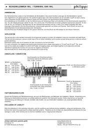
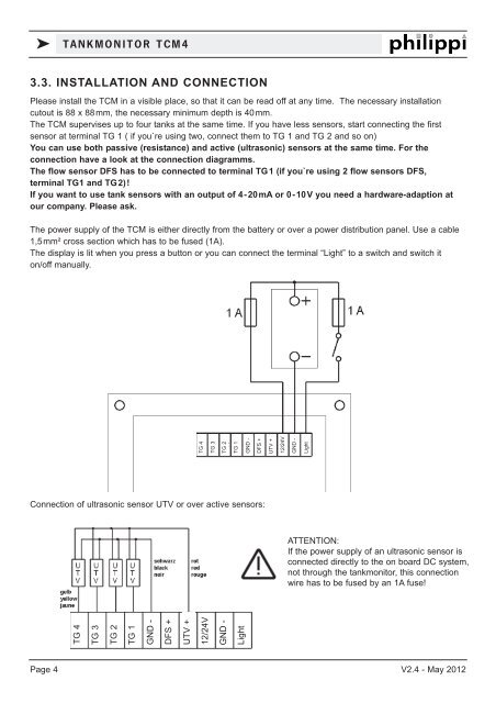
k TANKMONITOR TCM43.3. INSTALLATION AND CONNECTIONPlease install the TCM in a visible place, so that it can be read off at any time. The necessary installationcutout is 88 x 88mm, the necessary minimum depth is 40mm.The TCM supervises up to four tanks at the same time. If you have less sensors, start connecting the firstsensor at terminal TG 1 ( if you`re using two, connect them to TG 1 and TG 2 and so on)You can use both passive (resistance) and active (ultrasonic) sensors at the same time. For theconnection have a look at the connection diagramms.The flow sensor DFS has to be connected to terminal TG1 (if you`re using 2 flow sensors DFS,terminal TG1 and TG2)!If you want to use tank sensors with an output of 4-20mA or 0-10V you need a hardware-adaption atour company. Please ask.The power supply of the TCM is either directly from the battery or over a power distribution panel. Use a cable1,5mm² cross section which has to be fused (1A).The display is lit when you press a button or you can connect the terminal “Light” to a switch and switch iton/off manually.TG 4TG 3TG 2TG 1GND -DFS +UTV +12/24VGND -LightConnection of ultrasonic sensor UTV or over active sensors:ATTENTION:If the power supply of an ultrasonic sensor isconnected directly to the on board DC system,not through the tankmonitor, this connectionwire has to be fused by an 1A fuse!TG 4TG 3TG 2TG 1GND -DFS +UTV +12/24VGND -LightPage 4 V2.4 - May 2012