INSTRUCTION MANUAL INTRODUCTION - Philippi
INSTRUCTION MANUAL INTRODUCTION - Philippi
INSTRUCTION MANUAL INTRODUCTION - Philippi

Create successful ePaper yourself
Turn your PDF publications into a flip-book with our unique Google optimized e-Paper software.
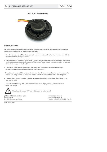
k ULTRASONIC SENSOR UTV<strong>INSTRUCTION</strong> <strong>MANUAL</strong><strong>INTRODUCTION</strong>the contactless measurement of a liquid level in a tank using ultrasonic technology does not requiremobile parts any more to be gotten dirty or damaged.-- The ultrasonic sensor UTV emits an acoustic wave perpendicularly to the liquid surface and detectsthe reflection from the liquid surface.-- The distance from the sensor to the liquid’s surface is computed based on the velocity of sound andthe time between emission and reception of the waves. To get correct measurement, the waves musthit the liquid surface vertically (±6°).-- Fluctuations in the level of the liquid in the tank due to movements become balanced by acontinuous measurement and a special computing algorithm.--The ultrasonic sensors UTV are accurate to 1 cm. The off-zone is 5 cm from the undersurface of thesensor. This range cannot be measured and the output value could differ to the real filling level.-- In cases where it is not possible to fix the sensor parallel to the liquid surface, the optional focustube can be used.-- The well sealed housing of the ultrasonic sensor is made of polyethylene, which withstandswater, fuel and oil.The ultrasonic sensor UTV can not be used for petrol tanks!philippi elektrische systeme gmbhwww.philippi-online.deNeckaraue 19info@philippi-online.deD-71686 Remseck am Neckar Telefon: +49 (0)7146/8744-0, Fax -22V2.5 - AUG 2013
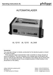
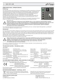
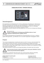
k ULTRASONIC SENSOR UTVINSTALLATIONmax. 6Grad 6°Medium LiquidThe ultrasonic sensor UTV has to be installed in aparallel position to the liquid, so that the acousticwave hits the liquid surface vertically (differencemax 6°).In order to get best results and to avoid influenceswhile heeling underway place the sensor in thecenter of the tank.The ultrasonic tank sensors can be easilyexchanged against an existing conventional tanksensor that has the attachment according to theSAE standard (5 mounting holes in the pitchdiameter of 54 mm).The hole in the tank for the installation of the ultrasonicsensor has to be min. 36 mm. (40 mm whileusing a focus tube).The mounting height above the tank is 25mm.If the measurement is incorrect (e.g. in waste watertanks) or the boat is heeling you can install anoptional focus tube UFT. It can be installed evenafterwards. The tube has to be cut to a length 2 - 3cm above the bottom of the tank.It`s ventilation hole is 5 cm under the sensor.Attention metal tanks: often the fixing screws aretightened too much. Then there`s a risk of anacoustic feedback. In this case the sensor mostlygives a “full” signal (Voltage over 2,5 V).Eventually a second gasket has to be placedbetween the sensor and the tank.SAE-NORMThe gasket and the (optional) distance ring match only in just one installation position.The gasket has a marking hole and a blind hole on one side. The side with the blind holeshows to the tank. The cable outlet is just over the marking hole. When using a distancering, the marking has to be at the top and shows where the cable outlet sits.ELEKTRISCHER ANSCHLUSSThe output signal of the ultrasonic sensor UTV is a voltage signal 0,5-2,5V.Power supply is a voltage 10-30 V.The black wire has to be connected to the minus (GND).The red wire has to be connected to the terminal UTV (tankmonitor TCM) or to plus (10-30V).The yellow wire gives the output signal (0,5-2,5V) and has to be connected to the terminalTG (1- 4) at the tank monitor TCM.Page 2 V2.5 - AUG 2013
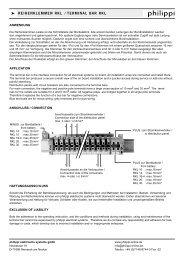
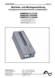
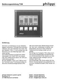
k ULTRASONIC SENSOR UTVCONNECTION TO TCMTUROTEST-INSTRUMENTS(Fuel-UTV, Water-UTV, Waste Water-UTV)Plus + 12/24VIllumination+ 12/24Vfrom distr. panel+ 12/24VUTVTCMTG (1-4)GNDredyellowblackUTV xxFuse1ANegativeyellowblackredOPERATIONTAKE The yellow sensor wire should never be connected to the supply power 12/24V -CARE the sensor will be destroyed if so!The power supply of the the tank measurement system should be switchable because the powerconsumption (ca. 50 mA/sensor) at permanent running is only reasonable while motoring.The exact output signal takes ca. 10-20s response time because the ultrasonic sensor is averaging themeasurement results. Also fluctuations in the tank cause a delay by the averaging process (50s).If there are very fast level changes (e.g. from empty to full in 2s) the sensor doesn`t react or only veryslowly (it can take up to 7 min.), because the sensors interprets this as a mistake.The sensor shows the last „reasonable“ tank level. After 10 minutes of non-utilisable measurementvalues the sensor shows empty. If necessary interrupt the power supply of the sensor for 1 s. to restartthe measurement.If the output signal doesn`t change even if the filling level has changed, please check if the ultrasonicsensor is installed completely parallel to the liquid level and the acoustic wave is reflected vertically.Maybe you have to install a focus tube to get better results; please have a look at the installation chapter-page 2.The off-zone range is 5 cm underneath the sensor and the sensor cannot determine the correct level, ifthe liquid surface is in that zone. Due to this fact the output can differ to the real filling level.TECHNICAL DATAPower supplyCurrent consumptionOutput signalResponse timeAveraging timeTemperature range11,5-30 V50mA0,5V (=empty) until 2,5V (=full)min. 200ms, max. 5s10 - 50 sec.-40°C bis +85°CV2.5 - AUG 2013 Page 3
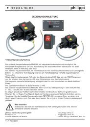
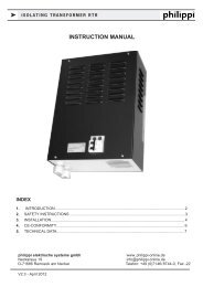
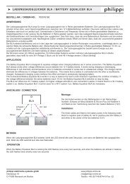
k ULTRASONIC SENSOR UTVDIMENSIONSAVAILABLE SENSORSfor water, fuel (diesel), grey water and waste water tanks:Tank depth Order-no. Focus tube: (incl. gasket)200mm 7 0219 3520 UTV20 also for belated installation:250mm 7 0219 3525 UTV25 UFT40 (400mm) 7 0219 9400300mm 7 0219 3530 UTV30 UFT80 (800mm) 7 0219 9800350mm7 0219 3535 UTV35400mm 7 0219 3540 UTV40 The focus tube has to be450mm 7 0219 3545 UTV45 cut to a length to 2-3 cm500mm 7 0219 3550 UTV50 above the bottom of the tank.600mm7 0219 3560 UTV60700mm7 0219 3570 UTV70800mm7 0219 3580 UTV80DISTANCE RING to balance the offzone:incl. gasket & stainless steel screws:7 0219 9025 UTS 25 (5x M5 x 60 mm)7 0219 9050 UTS 50 (5x M5 x 80 mm)GasketsUTSTake care of installation sequenceMATCHING ANALOG GAUGES for operation at 12V and 24V:2 0778 2001 Water UTV2 0778 2021 Fuel UTV2 0778 2041 Waste Water UTVDISPOSAL NOTEPlease take care of your local directives on waste electrical and electronic equipment.Please use collection points for waste electrical and electronic equipment.Page 4 V2.5 - AUG 2013