INSTRUCTION MANUAL - Philippi
INSTRUCTION MANUAL - Philippi
INSTRUCTION MANUAL - Philippi

You also want an ePaper? Increase the reach of your titles
YUMPU automatically turns print PDFs into web optimized ePapers that Google loves.
k ISOLATING TRANSFORMER RTR<br />
3. INSTALLATION<br />
The isolating transformers are designed for installation on a wall or the floor. It will be fixed by four<br />
fastening screws. Please install the isolation transformer in a well ventilated area..<br />
For installation a space in a locker or engine room of a diesel engine would suit. The isolating transformer<br />
has not to be installed in an engine room of a petrol engine, a battery locker and not in the<br />
neighbourhood of petrol tanks ( danger of explosion).<br />
For installation firstly the top cover must be removed. The cover is fixed by four M4 - crosshead-screws<br />
on the top of the device. There are four holes at the bottom of the device for the mounting. The four<br />
transportation locking screws have to be removed. After that the transformer can be screwed through<br />
these holes to the wall or floor. There are also four higher-laying screws - they are for fixation of the<br />
transformer to the housing - please don`t remove them.<br />
The compression couplings have to be fixed on the front side and the input and output wires have to be<br />
passed through.<br />
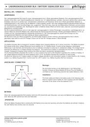
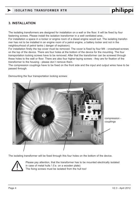
Demounting the four transportation locking screws:<br />
compression -<br />
couplings<br />
The isolating transformer will be fixed through this four holes on the bottom of the device.<br />
Please pay attention, that the transformer has to be mounted electrically isolated<br />
in case of metal hulls ! (f.e. on a wooden plate)<br />
The fixing screws must be isolated from the hull too!<br />
Page 4 V2.3 - April 2012