INSTRUCTION MANUAL - Philippi
INSTRUCTION MANUAL - Philippi
INSTRUCTION MANUAL - Philippi

You also want an ePaper? Increase the reach of your titles
YUMPU automatically turns print PDFs into web optimized ePapers that Google loves.
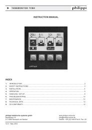
k ISOLATING TRANSFORMER RTR<br />
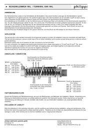
3.1 ELECTRICAL CONNECTION<br />
Connection Diagram:<br />
The input wires have to be connected to:<br />
L1 / N - MCB L1 / N<br />
PE - green/yellow terminal on the right hand side<br />
of the MCB<br />
The output wires have to be connected to:<br />
L1 - terminal L1<br />
N - terminal N<br />
PE - terminal PE<br />
The protective earth conductor at the output is<br />
separated to the shore power supply and connected to<br />
the neutral wire internally.<br />
For safety reasons there must be a RCBo - leakage<br />
protector installed on the output (f.e. a LAE 220).<br />
The nominal power of the external leakage protector<br />
RCBo has to match the output current of the isolating<br />
transformer ( see Technical Data).<br />
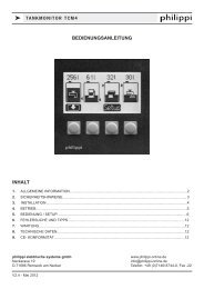
While in use both controllights are on:<br />
right: input winding<br />
left: output winding<br />
external:<br />
Input<br />
(Shore)<br />
Inrush current limiter<br />
Output<br />
(on board system)<br />
ACon<br />
board system<br />
Isolating transformer<br />
If you have a transformer with input switch over 115V / 230V please take care before<br />
switching on, that the selector switch is not in ”Zero”-position. That the electronic soft start<br />
works it has to be switched to the correlating input power. Otherwise maybe your shore<br />
power protection blows.<br />
V2.3 - April 2012 Page 5