Slope Stabilization Work Plan For Poplar River Management Board
Slope Stabilization Work Plan For Poplar River Management Board
Slope Stabilization Work Plan For Poplar River Management Board

You also want an ePaper? Increase the reach of your titles
YUMPU automatically turns print PDFs into web optimized ePapers that Google loves.
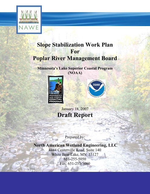
<strong>Slope</strong> <strong>Stabilization</strong> <strong>Work</strong> <strong>Plan</strong><br />
<strong>For</strong><br />
<strong>Poplar</strong> <strong>River</strong> <strong>Management</strong> <strong>Board</strong><br />
Minnesota’s Lake Superior Coastal Program<br />
(NOAA)<br />
January 18, 2007<br />
Draft Report<br />
Prepared by:<br />
North American Wetland Engineering, LLC<br />
4444 Centerville Road, Suite 140<br />
White Bear Lake, MN 55127<br />
651-255-5050<br />
Fax: 651-255-5060
TABLE OF CONTENTS<br />
EXECUTIVE SUMMARY .........................................................................................................................................1<br />
SECTION 1 -<br />
INTRODUCTION...........................................................................................................................3<br />
1.1 INTRODUCTION............................................................................................................................................3<br />
1.2 POPLAR RIVER WATER QUALITY ................................................................................................................3<br />
1.3 POPLAR RIVER MANAGEMENT BOARD........................................................................................................3<br />
1.4 PURPOSE......................................................................................................................................................3<br />
SECTION 2 - EXISTING CONDITIONS ............................................................................................................5<br />
2.1 SITE DESCRIPTION.......................................................................................................................................5<br />
2.2 POPLAR RIVER USE IMPAIRMENT................................................................................................................7<br />
2.3 SUMMARY OF MPCA 2003 NORTH SHORE WATER QUALITY AND FLOW MONITORING FINDINGS .............8<br />
2.4 SOIL CONDITIONS OF PROPOSED SITE .......................................................................................................10<br />
2.4.1 Soil Survey of Cook County .................................................................................................................10<br />
2.5 GEOLOGICAL CONDITIONS ........................................................................................................................12<br />
2.5.1 Summary of Geologic Conditions ........................................................................................................12<br />
2.5.2 Summary of Hydrogeologic Conditions...............................................................................................12<br />
SECTION 3 - POPLAR RIVER WATERSHED STUDY .................................................................................15<br />
3.1 PRELIMINARY WATERSHED INVESTIGATION .............................................................................................15<br />
3.2 WEPP MODELING OF SOURCES OF SEDIMENT ..........................................................................................15<br />
3.3 FIELD ASSESSMENT OF SLUMPS IN THE LOWER POPLAR RIVER ................................................................17<br />
3.3.1 Survey Findings ...................................................................................................................................18<br />
3.3.2 Discussion............................................................................................................................................21<br />
SECTION 4 - EXISTING SITE CONDITIONS ................................................................................................23<br />
4.1 MEGASLUMP WATERSHED INVESTIGATION...............................................................................................23<br />
4.2 POTENTIAL CAUSES...................................................................................................................................25<br />
4.3 DYNAMICS OF ROTATIONAL SLUMPS AND RIVER BANK EROSION ............................................................26<br />
4.3.1 Stream Erosion ....................................................................................................................................27<br />
4.3.2 Surface Runoff .....................................................................................................................................28<br />
4.3.3 Subsurface Saturation..........................................................................................................................29<br />
4.3.4 Wastewater Outfall ..............................................................................................................................30<br />
4.3.5 Natural Slumping.................................................................................................................................30<br />
4.4 NRRI MONITORING STATION DATA ANALYSIS ........................................................................................31<br />
SECTION 5 -<br />
MEGASLUMP CORRECTION OPTIONS...............................................................................35<br />
5.1 STREAM DIVERSION ..................................................................................................................................35<br />
5.2 J-HOOKS....................................................................................................................................................36<br />
5.3 PEAK FLOW REDUCTION ...........................................................................................................................37<br />
5.4 PEAK FLOW DIVERSION ............................................................................................................................37<br />
5.5 ARMORING ................................................................................................................................................39<br />
5.6 GRADE STABILIZATION .............................................................................................................................39<br />
5.7 CUT BACK TOP OF SLOPE ...........................................................................................................................45<br />
5.8 SUB-WATERSHED FLOW DIVERSION.........................................................................................................46<br />
SECTION 6 -<br />
RECOMMENDATIONS..............................................................................................................49<br />
6.1 STABILIZE THE BASE OF THE SLOPE WITH A VEGETATED GABION RETAINING WALL AND RIP RAP .........49<br />
6.2 WATERSHED DIVERSION AT THE TOP OF THE MEGASLUMP.......................................................................50
6.3 REPAIR GULLIES .......................................................................................................................................50<br />
6.4 STABILIZE THE MID-SECTION OF THE SLUMP ............................................................................................51<br />
6.5 ADDITIONAL OPTIONS TO BE CONSIDERED ...............................................................................................52<br />
6.6 ACKNOWLEDGEMENTS..............................................................................................................................52<br />
REFERENCES:.........................................................................................................................................................53<br />
APPENDIX A – CASE STUDIES OF SIMILAR PROJECTS .............................................................................57<br />
MASSACHUSETTS TURNPIKE ...................................................................................................................................57<br />
BRITISH COLUMBIA .................................................................................................................................................59
<strong>Slope</strong> <strong>Stabilization</strong> <strong>Work</strong> <strong>Plan</strong><br />
North American Wetland Engineering, LLC.<br />
January 18, 2007 4444 Centerville Rd, Suite 140<br />
<strong>Poplar</strong> <strong>River</strong> <strong>Management</strong> <strong>Board</strong> White Bear Lake, MN 55127<br />
Phone: 651-255-5050<br />
Fax: 651-255-5060<br />
Executive Summary<br />
The purpose of the report is to define feasible options for stabilizing a major slump zone called<br />
the Mega Slump. This report is issued for Technical Advisory Committee (TAC) review and<br />
public comments. Following the incorporation of comments, costs for the recommended<br />
alternatives will be analyzed and presented in the final report.<br />
Studies of the <strong>Poplar</strong> <strong>River</strong> indicate that the Mega Slump may responsible for as much as 65% of<br />
the sediment source to the lower <strong>Poplar</strong> <strong>River</strong>. The goal of this report was to define and evaluate<br />
potential causes of the slump and define feasible solutions for correcting the slumping problems.<br />
Possible causes that were identified in the report include:<br />
1. Rotational Slump<br />
2. Streambank Erosion<br />
3. Surface Runoff<br />
4. Subsurface Saturation<br />
5. Wastewater Outfall<br />
6. Natural Slumping<br />
It has been determined that a combination of surface runoff and streambank erosion have<br />
contributed the most to sediment transport into the river. Several alternatives were analyzed to<br />
stabilize the Mega Slump. These include:<br />
1. Stream Diversion<br />
2. J-Hooks<br />
3. Peak Flow Reduction<br />
4. Peak Flow Diversion<br />
5. Armoring<br />
6. Grade <strong>Stabilization</strong><br />
7. Cut Back Top of <strong>Slope</strong><br />
8. Sub-Watershed Flow Diversion<br />
The recommended alternative includes a combination of stabilization Best <strong>Management</strong><br />
Practices (BMPs) and involves breaking the slump down into three sections: top, middle, and<br />
bottom. The most critical portion of the slump for stabilization is the base. It is recommended to<br />
stabilize the base using a combination of a vegetated Gabion retaining wall on the steep banks<br />
and rip rap on both ends of the slump. The next priority to divert the watershed above the Mega<br />
Slump to prevent runoff water from a 7 acre area from discharging onto the slump. Finally, it is<br />
recommended to wait for a 2-year period to see how the slump reacts to these stabilization<br />
measures and then determine what approach, if any, needs be taken to stabilize the mid section of<br />
the slump.<br />
1
<strong>Slope</strong> <strong>Stabilization</strong> <strong>Work</strong> <strong>Plan</strong><br />
North American Wetland Engineering, LLC.<br />
January 18, 2007 4444 Centerville Rd, Suite 140<br />
<strong>Poplar</strong> <strong>River</strong> <strong>Management</strong> <strong>Board</strong> White Bear Lake, MN 55127<br />
Phone: 651-255-5050<br />
Fax: 651-255-5060<br />
2
<strong>Slope</strong> <strong>Stabilization</strong> <strong>Work</strong> <strong>Plan</strong><br />
North American Wetland Engineering, LLC.<br />
January 18, 2007 4444 Centerville Rd, Suite 140<br />
<strong>Poplar</strong> <strong>River</strong> <strong>Management</strong> <strong>Board</strong> White Bear Lake, MN 55127<br />
Phone: 651-255-5050<br />
Fax: 651-255-5060<br />
Section 1 - Introduction<br />
1.1 Introduction<br />
The <strong>Poplar</strong> <strong>River</strong> <strong>Management</strong> <strong>Board</strong> (PRMB) is evaluating methods for stabilizing the<br />
megaslump zone of the <strong>Poplar</strong> <strong>River</strong> located about 2 miles west of Lutsen, MN. The <strong>Poplar</strong><br />
<strong>River</strong> is a key source of tourism and recreation in Northern Minnesota and has been placed on<br />
the Clean Water Act 303(d) Impaired Waters List by the Minnesota Pollution Control Agency<br />
(MPCA). A wide cross section of state, community, and business leaders in the area have<br />
formed the PRMB in an effort to rectify the problems and eventually remove the river from the<br />
303(d) listing.<br />
1.2 <strong>Poplar</strong> <strong>River</strong> Water Quality<br />
The <strong>Poplar</strong> <strong>River</strong> was listed according to the Clean Water Act 303(d) list, issued in May 2004,<br />
for exceedances of the Minnesota mercury and turbidity water quality standard. Based on the<br />
MPCA’s turbidity monitoring data for 2002, the flow-weighted mean turbidity level does not<br />
meet the State of Minnesota standard of 10 NTU for designated trout streams. The megaslump<br />
has been identified as a major contributor to the sediment load in the river.<br />
1.3 <strong>Poplar</strong> <strong>River</strong> <strong>Management</strong> <strong>Board</strong><br />
An organizational meeting of the <strong>Poplar</strong> <strong>River</strong> <strong>Management</strong> <strong>Board</strong> (PRMB) was held on August<br />
4, 2005 in Lutsen. Resource agencies that participate in the PRMB are the DNR, US <strong>For</strong>est<br />
Service, Cook County, Cook County SWCD and Lutsen Township. Other contributing<br />
organizations include the MPCA, DNR Coastal Program, Coastal Zone <strong>Management</strong>, Natural<br />
Resources Research Institute and North American Wetland Engineering.<br />
The PRMB is an organization to promote water quality management activities of landowners on<br />
the <strong>Poplar</strong> <strong>River</strong>. The purpose of the PRMB is to protect and improve the water quality and<br />
other natural resources of the <strong>Poplar</strong> <strong>River</strong> through sound land use planning and management.<br />
The <strong>Board</strong> will be working toward the development of plans, projects and funding of water<br />
quality activities on the river. Ultimately, the PRMB wants to see the <strong>Poplar</strong> <strong>River</strong> achieve<br />
compliance with water quality standards and be removed from the 303(d) impaired waters list.<br />
1.4 Purpose<br />
The purpose of this report is to provide a work plan for the megaslump correction including an<br />
investigation into the causes and corrective options available to the PRMB with a focus on<br />
3
<strong>Slope</strong> <strong>Stabilization</strong> <strong>Work</strong> <strong>Plan</strong><br />
North American Wetland Engineering, LLC.<br />
January 18, 2007 4444 Centerville Rd, Suite 140<br />
<strong>Poplar</strong> <strong>River</strong> <strong>Management</strong> <strong>Board</strong> White Bear Lake, MN 55127<br />
Phone: 651-255-5050<br />
Fax: 651-255-5060<br />
effectiveness, aesthetics, and financial feasibility. This report also will look into and provide a<br />
summary of similar projects.<br />
4
<strong>Slope</strong> <strong>Stabilization</strong> <strong>Work</strong> <strong>Plan</strong><br />
North American Wetland Engineering, LLC.<br />
January 18, 2007 4444 Centerville Rd, Suite 140<br />
<strong>Poplar</strong> <strong>River</strong> <strong>Management</strong> <strong>Board</strong> White Bear Lake, MN 55127<br />
Phone: 651-255-5050<br />
Fax: 651-255-5060<br />
Section 2 - Existing Conditions<br />
2.1 Site Description<br />
The Lower <strong>Poplar</strong> <strong>River</strong> watershed begins at the waterfalls beneath the Superior Hiking Trail<br />
bridge and continues for 2.6 miles to the mouth at Lake Superior. The watershed includes 1,317<br />
acres of land including portions of Sections 20, 21, 28, 29, and 33 of Township 60N Range 3W.<br />
The river flows through property owned by Lutsen Mountains, Caribou Highlands Resort,<br />
Superior National Golf Course, Lutsen Resort, and various private and federal lands. Figure 2.1<br />
shows the Lower <strong>Poplar</strong> <strong>River</strong> Watershed and the megaslump location with topographic features.<br />
Figure 2.2 shows property ownership within the watershed boundaries.<br />
Megaslump<br />
Location<br />
Figure 2.1: Lower <strong>Poplar</strong> <strong>River</strong> watershed boundary.<br />
5
<strong>Slope</strong> <strong>Stabilization</strong> <strong>Work</strong> <strong>Plan</strong><br />
North American Wetland Engineering, LLC.<br />
January 18, 2007 4444 Centerville Rd, Suite 140<br />
<strong>Poplar</strong> <strong>River</strong> <strong>Management</strong> <strong>Board</strong> White Bear Lake, MN 55127<br />
Phone: 651-255-5050<br />
Fax: 651-255-5060<br />
Figure 2.2: Property Ownership within the Lower <strong>Poplar</strong> <strong>River</strong> Watershed<br />
6
<strong>Slope</strong> <strong>Stabilization</strong> <strong>Work</strong> <strong>Plan</strong><br />
North American Wetland Engineering, LLC.<br />
January 18, 2007 4444 Centerville Rd, Suite 140<br />
<strong>Poplar</strong> <strong>River</strong> <strong>Management</strong> <strong>Board</strong> White Bear Lake, MN 55127<br />
Phone: 651-255-5050<br />
Fax: 651-255-5060<br />
2.2 <strong>Poplar</strong> <strong>River</strong> Use Impairment<br />
Significant work from SE Group, Inc., a consultant to Lutsen Mountains, was completed to<br />
provide a picture of the resource issues facing federal, state and local units of government, the<br />
<strong>Poplar</strong> <strong>River</strong> <strong>Management</strong> <strong>Board</strong>, landowners, and the public. A summary of SE Group’s work<br />
is included.<br />
The Clean Water Act (CWA) requires that states publish, every two years, an updated list of<br />
streams and lakes that are not meeting water quality standards appropriate to their designated<br />
uses because of excess pollutants. As defined by the CWA,”… The term ‘pollutant’ means<br />
dredged spoil, solid waste, incinerator residue, sewage, garbage, sewage sludge, munitions,<br />
chemical wastes, biological materials, radioactive materials, heat, wrecked or discarded<br />
equipment, rock, sand, cellar dirt and industrial, municipal, and agricultural waste discharged<br />
into water…”<br />
The <strong>Poplar</strong> <strong>River</strong> was listed in the most recent 303(d) list, issued in May, 2004, for exceedances<br />
of the Minnesota mercury and turbidity water quality standards. Mercury exceedances are a<br />
statewide problem that originates from atmospheric sources principally derived from the<br />
combustion of fossil fuels and refuse (garbage). Mercury is associated with suspended solids<br />
because mercury attaches to soil particles. Therefore, one potential control measure for reducing<br />
mercury is to reduce suspended solids. However, there is no known water quality management<br />
practice that will result in compliance with the mercury standard in most rivers and lakes,<br />
including the <strong>Poplar</strong> <strong>River</strong>. It is believed that only air quality control measures will ultimately<br />
reduce the mercury emissions that will in turn reduce loading to receiving water bodies. This<br />
would increase the probability that downwind watersheds may achieve compliance.<br />
Turbidity, on the other hand, is a condition in rivers caused by suspended particles in the water.<br />
Turbidity is associated with erosion of soil and deposition in a water course so that it “clouds”<br />
the water to such an extent that it may exceed the water quality standard. Turbidity is measured<br />
directly by the MPCA. The presence of suspended solids in the water column is highly<br />
correlated with turbid conditions.<br />
The MPCA conducts regular water quality monitoring on streams and lakes. Various Lake<br />
Superior North Shore streams have been routinely monitored since 1972 under the Milestone<br />
Program. In this on-going monitoring, no water quality exceedances for turbidity have been<br />
observed. However, the on-going monitoring was periodic in nature, and did not focus on highflow<br />
periods such as spring runoff or after storms, during which the majority of sediment loading<br />
occurs. In 2001, the MPCA initiated a program called the North Shore Load Project to address<br />
the need for improved water quality information during high flow conditions. This project<br />
established a flow and event-based monitoring program, designed to focus on the high flow<br />
periods of primary sediment loading. As part of the North Shore Load Project on the <strong>Poplar</strong><br />
<strong>River</strong>, upstream and downstream monitoring sites were established so that the incoming water<br />
quality could be compared to the outgoing water quality. During storms and spring runoff the<br />
flow in the <strong>Poplar</strong> <strong>River</strong> can increase by as much as 800 percent. High flow events not only<br />
7
<strong>Slope</strong> <strong>Stabilization</strong> <strong>Work</strong> <strong>Plan</strong><br />
North American Wetland Engineering, LLC.<br />
January 18, 2007 4444 Centerville Rd, Suite 140<br />
<strong>Poplar</strong> <strong>River</strong> <strong>Management</strong> <strong>Board</strong> White Bear Lake, MN 55127<br />
Phone: 651-255-5050<br />
Fax: 651-255-5060<br />
wash accumulated sediments from the bed of the river, they also cut into the banks of the river<br />
causing stream bank erosion. Similarly, during storm events, runoff from the land, especially<br />
runoff from land with exposed soils, carries suspended solids into the river.<br />
Based on data collected through the North Shore Load Project, the MPCA concluded that the<br />
combination of land management practices and natural stream erosion results in exceedance of<br />
the turbidity standards in the <strong>Poplar</strong> <strong>River</strong> during high flow events. Therefore the <strong>Poplar</strong> <strong>River</strong>,<br />
along with other North Shore streams, was listed on the 303(d) impaired waters list.<br />
2.3 Summary of MPCA 2003 North Shore Water Quality and Flow Monitoring<br />
Findings<br />
Beginning in 2002, the Minnesota Pollution Control Agency (MPCA) initiated an intensive<br />
water quality and flow monitoring program on six representative North Shore tributaries to Lake<br />
Superior. In its 2003 report titled: “An Assessment of Representative Lake Superior Basin<br />
Tributaries, 2002”, the MPCA outlined the preliminary findings of this program.<br />
The ongoing MPCA monitoring program is a cooperative effort with Cook County, and also<br />
includes the US Geological Survey, Natural Resources Research Institute, University of<br />
Minnesota, the Minnesota Department of Natural Resources, the Lake Superior Coastal Program,<br />
Metropolitan Council – Environmental Services, as well as the City of Duluth. The <strong>Poplar</strong> <strong>River</strong><br />
watershed is included in this study.<br />
The streams in the study are intensively monitored using automated electronic stream flow<br />
measurement equipment. Water quality samples are collected utilizing a rigorous flow and<br />
event-based methodology that focuses sampling during spring runoff and large rainstorms. The<br />
constituents monitored during water quality sampling include total phosphorus and total<br />
suspended sediment, parameters associated with non-point source runoff.<br />
On the <strong>Poplar</strong> <strong>River</strong>, the MPCA conducted a paired sampling program, whereby water quality is<br />
monitored at two sites: one site located upstream of Lutsen Mountains resort, near Lutsen Falls,<br />
and a second located approximately 3 miles downstream at Superior National Golf Course<br />
(MPCA, 2003). The locations of the MPCA monitoring sites are shown in Figure 2.3.<br />
8
Figure 2.3: MPCA Lower <strong>Poplar</strong> <strong>River</strong> Monitoring Sites.<br />
9
<strong>Slope</strong> <strong>Stabilization</strong> <strong>Work</strong> <strong>Plan</strong><br />
North American Wetland Engineering, LLC.<br />
January 18, 2007 4444 Centerville Rd, Suite 140<br />
<strong>Poplar</strong> <strong>River</strong> <strong>Management</strong> <strong>Board</strong> White Bear Lake, MN 55127<br />
Phone: 651-255-5050<br />
Fax: 651-255-5060<br />
With respect to the <strong>Poplar</strong> <strong>River</strong>, the MPCA’s primary findings in the 2003 study were (MPCA,<br />
2003):<br />
♦<br />
♦<br />
♦<br />
Of the North Shore streams studied, the <strong>Poplar</strong> <strong>River</strong> exhibits a comparatively higher level<br />
of developed land use, representing 3.5% of the watershed area<br />
Water quality characteristics at the upstream <strong>Poplar</strong> <strong>River</strong> site were comparable to the<br />
water quality of the pristine Brule <strong>River</strong><br />
Loading of total suspended solids increases by a factor of approximately six between the<br />
upstream and downstream <strong>Poplar</strong> <strong>River</strong> sites<br />
♦ Loading of total phosphorus increases by a multiplier of approximately two between the<br />
upstream and downstream sites<br />
Based on the MPCA’s turbidity monitoring data, the flow-weighted mean turbidity level does not<br />
meet the State of Minnesota standard of 10 NTU for designated trout streams. The criteria used<br />
by the MPCA for a water body to be listed as impaired for turbidity, is an exceedance of greater<br />
than 10% of individual values. Therefore, the MPCA recommends intensive watershed<br />
management within the Lower <strong>Poplar</strong> <strong>River</strong> watershed to reduce sediment caused turbidity.<br />
With respect to sediment mass loads, the following excerpt from the 2003 report provides<br />
information on the loading rate of sediment to the <strong>Poplar</strong> <strong>River</strong>, in quantities of tons of sediment,<br />
occurring between the upper and lower monitoring sites (MPCA, 2003):<br />
In 2002, the amount of total suspended solids… [entering the <strong>Poplar</strong> <strong>River</strong>] between the<br />
upstream and downstream stations, a distance of 2.7 river miles, was on the order of 1,112 tons<br />
(e.g. 1,341 tons downstream versus 229 tons upstream)… Hence, there are substantial loading<br />
sources occurring in the <strong>Poplar</strong> <strong>River</strong> between the two stations. Examination of time series<br />
loading confirms that most of the total suspended solids mass loads occurred during the peak<br />
flow events of spring melt and storm events. The contributions from the permitted wastewater<br />
facility were not calculated as a part of this study.<br />
Sources of this erosion and nutrient loading are numerous. The river makes several sharp turns,<br />
causing bank erosion, as it winds through its valley… Some of this bank erosion could be termed<br />
“natural,” although the water volumes and runoff rates are increased due to human activity<br />
(land use change) in the valley, such as gully erosion… exposed clay soils, open areas (i.e.<br />
removal of trees), impervious surfaces (roads, roof tops and parking lots), and treated<br />
wastewater.<br />
2.4 Soil Conditions of Proposed Site<br />
2.4.1 Soil Survey of Cook County<br />
Cook County is one of four counties in Minnesota that does not have, and has not started, a soil<br />
survey. Consequently, the background information for the soils section of this report is taken from<br />
10
<strong>Slope</strong> <strong>Stabilization</strong> <strong>Work</strong> <strong>Plan</strong><br />
North American Wetland Engineering, LLC.<br />
January 18, 2007 4444 Centerville Rd, Suite 140<br />
<strong>Poplar</strong> <strong>River</strong> <strong>Management</strong> <strong>Board</strong> White Bear Lake, MN 55127<br />
Phone: 651-255-5050<br />
Fax: 651-255-5060<br />
the Minnesota Soil Atlas: International Falls-Two Harbors sheets, produced by the University of<br />
Minnesota Agricultural Experiment Station. The Minnesota Soil Atlas is a general guide that<br />
displays geomorphic areas and soil landscape units, but does not identify precise soil mapping units<br />
that are identified in a soil survey. The Minnesota Soil Atlas identifies the megaslump as being on<br />
the border of two main geomorphic areas: Highland Moraine and Highland Flutes. The Highland<br />
Moraine area is marked by loamy soils with rolling to hilly topography with numerous bedrock<br />
outcrops. The Highland Flutes area is characterized by rocky soils that form a strongly sloping<br />
boundary between the Moraine and Lake Superior. Four soil landscape units are identified by the<br />
Atlas as being near the property. These units are briefly described in Table 2.1, and Figure 2.4<br />
shows a map of the soil landscape units.<br />
Table 2.1: Minnesota Soil Atlas for Cook County<br />
Map unit Soil Unit Description<br />
LLWL (Pink) Loamy over Loamy Loams in drumlin-like uplands. Well and<br />
Moderately well drained.<br />
RLWL (Orange) Silty or Loamy over<br />
Rock<br />
Gravelly sandy loam over bedrock and<br />
gravelly sandy loam. Well drained.<br />
CCWL (Purple) Clayey over Clayey Very fine clay on gently sloping to sloping<br />
lucustrine lands. Moderately well drained.<br />
R (White) Bedrock Bedrock outcrops within gravelly sandy<br />
loam. Well to excessively drained.<br />
Lower <strong>Poplar</strong><br />
<strong>River</strong> Watershed<br />
Boundary<br />
Megaslump<br />
Location<br />
Figure 2.4: Soil Atlas of Lutsen Mountains<br />
11
<strong>Slope</strong> <strong>Stabilization</strong> <strong>Work</strong> <strong>Plan</strong><br />
North American Wetland Engineering, LLC.<br />
January 18, 2007 4444 Centerville Rd, Suite 140<br />
<strong>Poplar</strong> <strong>River</strong> <strong>Management</strong> <strong>Board</strong> White Bear Lake, MN 55127<br />
Phone: 651-255-5050<br />
Fax: 651-255-5060<br />
2.5 Geological Conditions<br />
2.5.1 Summary of Geologic Conditions<br />
The <strong>Poplar</strong> <strong>River</strong> is located in a moraine complex on the border between the Rainy Lobe and the<br />
Superior Lobe that was deposited during the Wisconsinan Glaciation. The Superior Lobe traveled<br />
parallel to Lake Superior in a southwestern direction against the Rainy Lobe, which moved in a more<br />
southerly direction. The surficial geology consists of unconsolidated materials generally less than six<br />
feet deep over fractured bedrock. Dominant soil textures vary from loam to gravelly sandy loam.<br />
The glacial sediments in the Lutsen area are underlain by the North Shore Volcanic Group, a series<br />
of igneous rocks with interbeds of conglomerates and other clastic rocks. The lava rocks were<br />
formed during successive lava flows from the Mid-Continent Rift System. The Rift System is a<br />
spreading feature that formed when North America was splitting apart approximately 1.1 billion<br />
years ago. According to the USGS, the rift extends from the east end of Lake Superior to Duluth,<br />
then south along the Minnesota-Wisconsin border and west to Kansas. When the rifting stopped, a<br />
large basin was left behind that over millions of years, filled with sediments. During the last glacial<br />
period, the sediments were eroded away by the scouring action of the glacier and Lake Superior and<br />
its basin was formed.<br />
2.5.2 Summary of Hydrogeologic Conditions<br />
Groundwater in the region originates as precipitation on the surface that has infiltrated down through<br />
the overlying sediments and into the fractured bedrock. Figure 2.5 shows a representation of the<br />
groundwater flow. Once groundwater reaches the bedrock, its movement is totally dependent upon<br />
secondary openings in the rock (fractures, joints, cracks, and cavities). Rock type has little effect on<br />
groundwater flow. At the megaslump, the groundwater is likely staying close to the ground surface,<br />
thereby saturating the soil, making it more plastic and exacerbating the effects of the slump.<br />
Figure 2.5: Representation of groundwater flow at Lutsen Mountains<br />
The average groundwater elevation at the site is approximately 1,000 feet above mean sea level. On<br />
a regional scale, groundwater flows west towards the <strong>Poplar</strong> <strong>River</strong> and then south towards Lake<br />
Superior. However, it is likely that the local groundwater direction is more variable due to pockets of<br />
12
<strong>Slope</strong> <strong>Stabilization</strong> <strong>Work</strong> <strong>Plan</strong><br />
North American Wetland Engineering, LLC.<br />
January 18, 2007 4444 Centerville Rd, Suite 140<br />
<strong>Poplar</strong> <strong>River</strong> <strong>Management</strong> <strong>Board</strong> White Bear Lake, MN 55127<br />
Phone: 651-255-5050<br />
Fax: 651-255-5060<br />
perched groundwater and variable subsurface deposits. The surface water is of high quality with less<br />
than 50 mg/L of total dissolved solids, but the MPCA classifies the <strong>Poplar</strong> <strong>River</strong> area as a moderaterisk<br />
zone for groundwater contamination.<br />
13
<strong>Slope</strong> <strong>Stabilization</strong> <strong>Work</strong> <strong>Plan</strong><br />
North American Wetland Engineering, LLC.<br />
January 18, 2007 4444 Centerville Rd, Suite 140<br />
<strong>Poplar</strong> <strong>River</strong> <strong>Management</strong> <strong>Board</strong> White Bear Lake, MN 55127<br />
Phone: 651-255-5050<br />
Fax: 651-255-5060<br />
14
<strong>Slope</strong> <strong>Stabilization</strong> <strong>Work</strong> <strong>Plan</strong><br />
North American Wetland Engineering, LLC.<br />
January 18, 2007 4444 Centerville Rd, Suite 140<br />
<strong>Poplar</strong> <strong>River</strong> <strong>Management</strong> <strong>Board</strong> White Bear Lake, MN 55127<br />
Phone: 651-255-5050<br />
Fax: 651-255-5060<br />
Section 3 - <strong>Poplar</strong> <strong>River</strong> Watershed Study<br />
3.1 Preliminary Watershed Investigation<br />
In order to help quantify the overall and relative contributions of sediment from various land<br />
uses and land cover types within the Lower <strong>Poplar</strong> <strong>River</strong> watershed, SE Group conducted a study<br />
of the Lower <strong>Poplar</strong> <strong>River</strong>. A complete discussion of the model can be found in the 2006 AUAR<br />
and the report completed by SE Group. This section provides a summary of the findings.<br />
3.2 WEPP Modeling of Sources of Sediment<br />
SE Group utilized the US Department of Agriculture – Agricultural Research Service Water<br />
Erosion Prediction Project (WEPP) model to compute sediment detachment for the various land<br />
cover types within the watershed. The model was used to compute detachment only, and did not<br />
account for routing and buffering (which reduce actual yields to the stream system), in order to<br />
provide an approximate order-of-magnitude estimate of the sediment generation in the lower<br />
watershed. Because the analysis did not account for factors that can result in the removal and<br />
deposition of sediment from water before reaching the river, it represents a conservative analysis<br />
(i.e., it overestimates the contribution of sediment to the <strong>Poplar</strong> <strong>River</strong> from the land uses of<br />
interest).<br />
In order to compute total sediment detachment, the following computation was performed: a<br />
cross-multiplication of: (land cover area) versus (slope area) versus (soil texture) versus (erosion<br />
rate) from WEPP. The output of the process provides an estimate of soil detachment, and not<br />
actual delivery to the stream system. The detachment-only analysis is likely over-representing<br />
the amount of sediment produced in the lower watershed. The results of the WEPP analysis are<br />
outlined in Table 3.1.<br />
15
<strong>Slope</strong> <strong>Stabilization</strong> <strong>Work</strong> <strong>Plan</strong><br />
North American Wetland Engineering, LLC.<br />
January 18, 2007 4444 Centerville Rd, Suite 140<br />
<strong>Poplar</strong> <strong>River</strong> <strong>Management</strong> <strong>Board</strong> White Bear Lake, MN 55127<br />
Phone: 651-255-5050<br />
Fax: 651-255-5060<br />
Table 3.1: WEPP Sediment Detachment Results versus Measured Sediment Mass Loading.<br />
Class<br />
Area (Acres)<br />
Ski Trail – Tall Grass 32.6 12.6<br />
Ski Trail – Short Grass 28.8 24.6<br />
Bare Soils within Slump Zones 2.6 30<br />
Roads - Lutsen 6.8 84<br />
Roads - Non-Lutsen 0.5 10.1<br />
<strong>For</strong>est 183.4 12.7<br />
Natural Opening 5.8 0.5<br />
Golf Course 14.4 5.1<br />
WEPP-modeled Sediment from Land Surface 274.9 179.6<br />
Measured Suspended Sediment Loading to the Stream<br />
(MPCA 2003) -- 1,112<br />
Difference between Measured and Modeled Sediment<br />
Loading -- 932.4<br />
Load<br />
(Tons/Year)<br />
The results of the WEPP model indicate that approximately 180 tons of sediment per year<br />
detaches from the various land cover types along the gorge of the Lower <strong>Poplar</strong> <strong>River</strong>. Not all of<br />
this sediment is ultimately delivered to the stream system. The filtering effects of vegetated<br />
buffers, especially forest, are not accounted for in this simplistic analysis.<br />
It is instructive to compare the modeled contribution from land uses in comparison to the<br />
sediment loading between the upper and lower monitoring sites, as measured by the MPCA.<br />
This comparison is shown in Figure 3.1.<br />
16
<strong>Slope</strong> <strong>Stabilization</strong> <strong>Work</strong> <strong>Plan</strong><br />
North American Wetland Engineering, LLC.<br />
January 18, 2007 4444 Centerville Rd, Suite 140<br />
<strong>Poplar</strong> <strong>River</strong> <strong>Management</strong> <strong>Board</strong> White Bear Lake, MN 55127<br />
Phone: 651-255-5050<br />
Fax: 651-255-5060<br />
2002 Lower <strong>Poplar</strong> <strong>River</strong><br />
Sediment Loading<br />
180<br />
Tons<br />
Land Use (WEPP)<br />
Other Source--<br />
932<br />
Tons<br />
Area of the pie represents the total of 1,112 Tons<br />
of Sediment loading, as measured by MPCA in<br />
2002, between upper and Lower <strong>Poplar</strong> <strong>River</strong> sites.<br />
Figure 3.1: 2002 Lower <strong>Poplar</strong> <strong>River</strong> Measured Sediment Mass Loading.<br />
The model suggests that total sediment detachment within the Lower <strong>Poplar</strong> <strong>River</strong> produces 180<br />
tons per year of sediment. Even if all of this sediment reaches the river, over 900 tons per year<br />
would remain unaccounted for in the land use modeling, indicating that other sources of<br />
sediment are not accounted for in the model.<br />
3.3 Field Assessment of Slumps in the Lower <strong>Poplar</strong> <strong>River</strong><br />
A field watershed assessment survey was conducted to characterize slumps within the Lower<br />
<strong>Poplar</strong> <strong>River</strong> watershed. The survey covered approximately 3 river miles from the upper MPCA<br />
monitoring station downstream to the Highway 61 crossing. Within the survey area, the <strong>Poplar</strong><br />
<strong>River</strong> flows through Lutsen Mountains Ski Area and the Superior National Golf Course.<br />
Approximately 3.5 percent of the total <strong>Poplar</strong> <strong>River</strong> watershed area (upper and lower) is<br />
considered to be developed, with most of the developed land use located below the upper<br />
monitoring station (MPCA, 2003). The Methodology for the watershed assessment is included<br />
in the 2006 AUAR and the report completed by SE Group.<br />
17
<strong>Slope</strong> <strong>Stabilization</strong> <strong>Work</strong> <strong>Plan</strong><br />
North American Wetland Engineering, LLC.<br />
January 18, 2007 4444 Centerville Rd, Suite 140<br />
<strong>Poplar</strong> <strong>River</strong> <strong>Management</strong> <strong>Board</strong> White Bear Lake, MN 55127<br />
Phone: 651-255-5050<br />
Fax: 651-255-5060<br />
3.3.1 Survey Findings<br />
During the survey, 16 slumps were located on the <strong>Poplar</strong> <strong>River</strong> between the upper monitoring<br />
station and the Highway 61 crossing. Two additional headwater slumps were identified on an<br />
un-named intermittent drainage between Moose and Mystery Mountains, informally named<br />
during the survey as “Moose Creek” (MC). These slumps on Moose Creek were not factored in<br />
estimating the total sediment delivered to the <strong>Poplar</strong> <strong>River</strong> due to their distance from the <strong>Poplar</strong><br />
<strong>River</strong> and uncertainty regarding sediment in this reach of the tributary. A map portraying the<br />
mapped slump zones is shown in Figure 3.2.<br />
The average slope of all slumps was 63 percent, with a maximum of 82 percent and a minimum<br />
of 52 percent (see Table 3.2). The slumps on the <strong>Poplar</strong> <strong>River</strong> range in area from 0.01 to 1.44<br />
acres with an average 0.15 acres. Soil detachment estimates range from approximately 40 tons<br />
to a high of almost 8,000 tons, with a total estimated contribution to the <strong>Poplar</strong> <strong>River</strong> of 12,000<br />
tons, over an unknown time period. This soil detachment from the slumps helps explain the<br />
“other source” of sediment shown in Figure 3.1.<br />
18
Megaslump<br />
Figure 3.2: Slump Zones in Lower <strong>Poplar</strong> <strong>River</strong> Watershed.<br />
19
<strong>Slope</strong> <strong>Stabilization</strong> <strong>Work</strong> <strong>Plan</strong><br />
North American Wetland Engineering, LLC.<br />
January 18, 2007 4444 Centerville Rd, Suite 140<br />
<strong>Poplar</strong> <strong>River</strong> <strong>Management</strong> <strong>Board</strong> White Bear Lake, MN 55127<br />
Phone: 651-255-5050<br />
Fax: 651-255-5060<br />
Table 3.2: Summary of Slump Zones Mapped within the Lower <strong>Poplar</strong> <strong>River</strong> Watershed.<br />
Site ID<br />
Location<br />
(RM)<br />
Soil<br />
Texture<br />
Soil Color<br />
Percent<br />
<strong>Slope</strong><br />
Area<br />
(acres)<br />
Rough<br />
Estimate of<br />
Sediment<br />
(tons)<br />
MC-LB-08292005-01 Moose Clay 7.5 YR 5/4 58% 0.04 85.91<br />
Creek<br />
MC-RB-08292005-02 Moose Silty Clay 5 YR 5/4 52% 0.13 296.87<br />
Creek Loam<br />
PR-LB-08272005-01 Clay Loam 7.5 YR 3/4 68% 0.04 39.92<br />
PR-LB-08272005-02 Sandy Loam 7.5 YR 5/4 55% 0.03 169.87<br />
PR-LB-08272005-03<br />
Silty Clay 7.5 YR 3/2 67% 0.10 305.56<br />
Loam<br />
PR-LB-08282005-04 Sandy Loam N/A 65% 0.15 970.67<br />
PR-LB-08282005-05<br />
Silty Clay 7.5 YR 3/4 58% 0.02 56.53<br />
Loam<br />
PR-LB-08282005-06 Loamy Sand 7.5 YR 4/2 82% 0.04 192.80<br />
PR-LB-08282005-07<br />
Silty Clay 7.5 YR 3/2 65% 0.13 442.59<br />
Loam<br />
PR-LB-08282005-09<br />
Silty Clay 7.5 YR 3/4 57% 0.04 204.78<br />
Loam<br />
PR-LB-08302005-01 N/A N/A 60% 0.01 10.68<br />
PR-RB-08282005-01<br />
Silty Clay 7.5 YR 4/3 55% 0.01 56.74<br />
Loam<br />
PR-RB-08282005-02<br />
Silty Clay 7.5 YR 4/4 54% 0.03 108.38<br />
Loam<br />
PR-RB-08282005-03<br />
Silty Clay 7.5 YR 3/3 60% 0.05 161.82<br />
Loam<br />
PR-RB-08282005-04<br />
Silty Clay 7.5 YR 4/6 65% 0.07 283.61<br />
Loam<br />
PR-RB-08282005-05<br />
Silty Clay 7.5 YR 3/4 62% 0.12 742.40<br />
Loam<br />
PR-RB-08282005-08<br />
Sandy Clay 5 YR 4/4 79% 0.11 497.94<br />
Loam<br />
PR-RB-08282005-10 (1)<br />
Silty Clay 5 YR 4/4 79% 1.44 7,836.18<br />
Loam<br />
Total Estimated Sediment Contribution to the <strong>Poplar</strong> <strong>River</strong> (tons) 12,080.47<br />
(1) Slump 10 is the megaslump
<strong>Slope</strong> <strong>Stabilization</strong> <strong>Work</strong> <strong>Plan</strong><br />
North American Wetland Engineering, LLC.<br />
January 18, 2007 4444 Centerville Rd, Suite 140<br />
<strong>Poplar</strong> <strong>River</strong> <strong>Management</strong> <strong>Board</strong> White Bear Lake, MN 55127<br />
Phone: 651-255-5050<br />
Fax: 651-255-5060<br />
3.3.2 Discussion<br />
Slumps within the Lower <strong>Poplar</strong> <strong>River</strong> Watershed occur most frequently on steep slopes where<br />
the slope angle exceeds 50 percent. As the river flows through the golf course, the channel<br />
enters a narrow bedrock canyon. As a result, little slumping is evident as the river passes<br />
through the golf course property.<br />
There is currently insufficient information available to definitively link the occurrence of slumps<br />
within the lower portion of the <strong>Poplar</strong> <strong>River</strong> watershed to specific causative factors. Factors that<br />
may contribute to slumping can be from natural causes, increased runoff from watershed<br />
activities, snowmaking, redirecting runoff that wets soils contributing to slumping, removal of<br />
tree cover, roads, construction activities and impervious surfaces. Understanding these causal<br />
factors gives rise to solutions for mitigation of human activities in the watershed. This is the<br />
function of the TMDL process underway on the <strong>Poplar</strong> <strong>River</strong>.<br />
Based on watershed characteristics and land management activities, the slumps mapped upstream<br />
of Mystery Mountain on the west bank appear to be natural in character. When these slumps<br />
were traced upslope to characterize the land use in the vicinity of their origins, there was no<br />
evidence of anthropogenic influences. Other slumps between ski runs appear to have<br />
anthropogenic influences that have exacerbated natural slumping along the <strong>Poplar</strong> <strong>River</strong>.<br />
Of particular importance in terms of relative sediment contribution is the megaslump (PR-RB-<br />
08282005-10), located across the <strong>Poplar</strong> <strong>River</strong> from the base of Moose Mountain. This slump is<br />
evident on historic aerial photographs dating back to the 1930s, although at that time it appears<br />
to have been several isolated gullies. Over time these gullies have become connected as erosive<br />
forces continued to affect the hillslope. As surveyed, the slump is approximately 1.44 acres in<br />
area. Potentially contributing to the occurrence of sediment detachment from the slump, a<br />
wastewater outflow is located above the slump headcut. This outflow has been fitted with a<br />
sleeve to convey effluent to the river without further effects to the slump. This sleeve, however,<br />
appears to be potentially unable to withstand pressures at the pipe outlet into the sleeve, raising<br />
concerns that the sleeve could separate from the pipe. This discharge system was installed at the<br />
request of, and is under the supervision of the MPCA. It is anticipated that the MPCA will<br />
continue to direct the interaction between the outfall and the slump.<br />
The total approximate mass of sediment that these slumps have contributed to the <strong>Poplar</strong> <strong>River</strong><br />
over time was estimated by calculating a rough volume of the slump zone and utilizing the<br />
estimated bulk density of the soil. Bulk densities were obtained from the soil mapping available<br />
for the area on the NRCS website. This estimated amount of sediment is based on the<br />
assumptions that half of the total volume of the slump has been delivered to the stream while the<br />
other half remains on the slope. Additionally, it assumes that the amount of sediment has been<br />
contributed since the slump formed. Analysis of historic aerial photographs did not provide a<br />
sufficient resolution to effectively determine slump age. Therefore the length of time it has taken<br />
to produce an approximate total of 12,000 tons of sediment contribution is unknown.<br />
The order of magnitude of sediment loading associated with this estimate provides a clue that<br />
mass wasting is caused by riverbank erosion action within the slump zones. This likely accounts<br />
21
<strong>Slope</strong> <strong>Stabilization</strong> <strong>Work</strong> <strong>Plan</strong><br />
North American Wetland Engineering, LLC.<br />
January 18, 2007 4444 Centerville Rd, Suite 140<br />
<strong>Poplar</strong> <strong>River</strong> <strong>Management</strong> <strong>Board</strong> White Bear Lake, MN 55127<br />
Phone: 651-255-5050<br />
Fax: 651-255-5060<br />
for a large fraction of the difference between the measured sediment yield at the Lower <strong>Poplar</strong><br />
monitoring site, and the WEPP-modeled sediment detachment associated with land use.<br />
22
<strong>Slope</strong> <strong>Stabilization</strong> <strong>Work</strong> <strong>Plan</strong><br />
North American Wetland Engineering, LLC.<br />
January 18, 2007 4444 Centerville Rd, Suite 140<br />
<strong>Poplar</strong> <strong>River</strong> <strong>Management</strong> <strong>Board</strong> White Bear Lake, MN 55127<br />
Phone: 651-255-5050<br />
Fax: 651-255-5060<br />
Section 4 - Existing Site Conditions<br />
4.1 Megaslump Watershed Investigation<br />
On September 26, 2006, North American Wetland Engineering made a site visit to assess the<br />
characteristics of the megaslump area. The purpose of the site visit was to inspect the face of the<br />
slump and gather information relating to potential causes of the slump. At the time of the<br />
investigation, the river was at a very low stage and the weather was overcast and drizzling.<br />
Photographs were taken of the entire slump area and are included in Appendix A.<br />
On the face of the slump, rill erosion was prevalent as were a number of large gullies. The<br />
effluent pipe from the Caribou Highlands wastewater treatment lagoons was located at the top of<br />
the largest gully,. There was water leaking out of this pipe into the gully and the soil was<br />
saturated at this location. There were grasses growing on the face of the slump in some areas<br />
and certain areas had well established tree growth. At the top of the slump, undercutting of the<br />
bank was taking place and roots from trees were exposed.<br />
There were three main portions of the slump that were identified. The first was the upstream<br />
third of the slump. This area had numerous gullies and the most prevalent rill erosion. There<br />
were well established trees at the base of the slump adjacent to the river. The second area was<br />
the middle third of the slump. This area had exposed soils throughout the entire height of the<br />
slump. This area also had the steepest slope from the river to the top of the slump. The<br />
downstream third of the slump had exposed soils on the top portion of the slump and well<br />
established tree growth on the bottom two thirds of the slump. The slope in this area was not as<br />
steep as the middle third of the slump area. It was determined that three different approaches to<br />
stabilize the slope may be necessary in these different areas.<br />
On November 30, 2006, North American Wetland Engineering investigated potential watershed<br />
issues within the megaslump area. Specifically, the investigation was to determine possible<br />
surface water runoff contributions to the area on the upland portion of the megaslump. The<br />
<strong>Poplar</strong> <strong>River</strong> itself was also re-examined to identify peak flow levels, existing armoring,<br />
potential physiographic disruptions, and potential diversion routes.<br />
<strong>River</strong> investigation – The <strong>Poplar</strong> <strong>River</strong> channel takes two sharp bends near the megaslump. One<br />
upstream near where Lutsen Mountains removes river water for snow making and one that<br />
effectively defines the boundaries of the megaslump. The snow making withdrawal and storage<br />
is located just after a bend in the river upstream from the megaslump. The surrounding land is<br />
only a few feet higher than the river.
<strong>Slope</strong> <strong>Stabilization</strong> <strong>Work</strong> <strong>Plan</strong><br />
North American Wetland Engineering, LLC.<br />
January 18, 2007 4444 Centerville Rd, Suite 140<br />
<strong>Poplar</strong> <strong>River</strong> <strong>Management</strong> <strong>Board</strong> White Bear Lake, MN 55127<br />
Phone: 651-255-5050<br />
Fax: 651-255-5060<br />
During spring melt and summer storm events, the level of the <strong>Poplar</strong> <strong>River</strong> can rise 4-5 feet from<br />
normal flow conditions. Natural armoring along the bank of the river offers some protection<br />
during lesser fluctuation, but is insufficient during these peak flows. This has provided unique<br />
problems for Caribou Highlands which discharges over the megaslump through a specially<br />
designed pipe and hose system. While the hose was originally intended to be left in place year<br />
round, additional slope damage caused by high water events has repeatedly buried or damaged<br />
the hose so that the resort now stores the hose on the top of the slope except when discharging.<br />
They also secure the discharge pipe with cabling and backfill along the river shore.<br />
Across the <strong>Poplar</strong> <strong>River</strong> from the megaslump is a side channel on the inside of the corner of the<br />
riverbend that has been identified for stream diversion. This will likely be difficult since there is<br />
not enough of a rock bar between the side and main channels to keep the peak flows away from<br />
the megaslump. Additional buildup of the bar is possible, but would reduce river capacity and<br />
may cause flooding at the base of Moose Mountain and its associated ski runs.<br />
The megaslump was visible in aerial photos from as early as 1931 (SE Group). In the past it was<br />
a series of individual channels that have merged overtime to its current size. Individual channels<br />
are still present as deeper cuts in the upper slope narrowing to preferred gullies along the river.<br />
Three main cut areas exist with mass wasting present evenly across the slope for the rest of the<br />
area. Buttressed growth, which is indicative of ground movement, is present in the surviving<br />
trees across the slope. It has been suggested that this indicates rotational slump, but all of the<br />
trees tend to bend out towards the river rather than away as would be expected from a rotational<br />
slump condition.<br />
The subwatershed above the megaslump was examined to identify how much land was being<br />
drained into the megaslump area and to determine what options might be available for providing<br />
drainage to the area. A topographic map with 5-foot contours was provided by the Lutsen<br />
Mountains. From this map a ridge appears to direct the drainage to the southern portion of the<br />
megaslump. The ridge is connected to the southeastern corner of the Caribou Highlands<br />
wastewater lagoon. Another ridge separates water flowing to the megaslump from water flowing<br />
to the road that connects Caribou Highlands with the bridge to Moose Mountain. Figure 4.1<br />
outlines the subwatershed drainage area.<br />
24
<strong>Slope</strong> <strong>Stabilization</strong> <strong>Work</strong> <strong>Plan</strong><br />
North American Wetland Engineering, LLC.<br />
January 18, 2007 4444 Centerville Rd, Suite 140<br />
<strong>Poplar</strong> <strong>River</strong> <strong>Management</strong> <strong>Board</strong> White Bear Lake, MN 55127<br />
Phone: 651-255-5050<br />
Fax: 651-255-5060<br />
N<br />
Megaslump area<br />
Subwatershed Area<br />
~ 7.3 acres<br />
Figure 4.1: Subwatershed Area above the Megaslump<br />
The access road that begins at the southeast corner of the Caribou Highlands lagoon has ditches<br />
that provide drainage for the road and for the sideslopes of the lagoon. These ditches could be<br />
utilized to help drain the entire area above the megaslump. To determine the drainage options,<br />
additional survey data is needed.<br />
4.2 Potential Causes<br />
Free-flowing streams, where stream banks are unconfined by natural or anthropogenic structures,<br />
tend to establish a state of equilibrium. By this equilibrium, erosion at one location is roughly<br />
balanced by deposition at another. Even streams whose channels appear to be stable and welldefined<br />
will tend to adjust dynamically over extended time periods. In a state of equilibrium, the<br />
erosion and sedimentation process can help to maintain beneficial aquatic ecosystem structures,<br />
such as gravel beds that sometimes support fish spawning habitat. Likewise, dynamic fluvial<br />
processes will tend to establish series of pools, riffles and runs that provide aquatic habitat.<br />
(Connecticut <strong>River</strong> Joint Commission, 1996)<br />
Natural erosion and slope movement along stream channels is a dynamic process that provides<br />
sediment to the system based on many variables, including rainfall, soil properties and<br />
vegetation. As a result, natural systems under equilibrium may receive acute inputs of sediment<br />
from slope movements. Such movements may be rather small in scale, providing a plume of<br />
sediment that is conveyed downstream until a new equilibrium is attained. Conversely, large<br />
slope movements into the channel may be of sufficient mass to cause channel migration, thereby<br />
25
<strong>Slope</strong> <strong>Stabilization</strong> <strong>Work</strong> <strong>Plan</strong><br />
North American Wetland Engineering, LLC.<br />
January 18, 2007 4444 Centerville Rd, Suite 140<br />
<strong>Poplar</strong> <strong>River</strong> <strong>Management</strong> <strong>Board</strong> White Bear Lake, MN 55127<br />
Phone: 651-255-5050<br />
Fax: 651-255-5060<br />
eliminating the pool/riffle habitat entirely and causing the establishment of entirely new aquatic<br />
habitat.<br />
4.3 Dynamics of Rotational Slumps and <strong>River</strong> Bank Erosion<br />
Where river banks are particularly steep, with highly erodible soils, the slope stability for the<br />
bank may not be sufficient to resist lateral erosional forces or channel migration. Where highly<br />
erodible soils that occur on steep slope aspects, mass failure via rotational slumping is a potential<br />
outcome. <strong>Slope</strong> movement is a natural process, but can be accentuated by undercutting of the<br />
base of slopes, loss of stabilizing vegetation, or the diversion of natural drainage. A rotational<br />
slump is a common type of slide (Batterson, 1999). Rotational slumping occurs when soils<br />
material moves down and laterally along a concave surface. A rotational slump is illustrated in<br />
the Figure 4.2<br />
Illustration courtesy of Waikato Regional Council, New Zealand.<br />
Figure 4.2: Rotational Slump<br />
Often, shallow water in the soils, along the concave movement plane, acts as a lubricating agent<br />
(Batterson, 1999). As described in Batterson, 1999, “…the simplest form of rotational slump is<br />
when a small block of land shifts downward. The upper surface of the slide appears to rotate<br />
backward and often remains intact.” Following mass failure, slump material accumulates at the<br />
bank toe. As the action of the river directs energy along the stream banks, debris is removed by<br />
lateral erosion prior to increased steepening. This action can contribute to further mass failures.<br />
Thus the process of sediment production from slump zones is a result of the combined effects of<br />
lateral erosion and mass instability leading to erosion of the resulting unstable river banks.<br />
Rotational slumping is often characterized by trees that lean backwards or have backwards<br />
rotations as the tree begins to grow vertically again. At the megaslump most of the surviving<br />
trees display a forward rotation as the trees have tipped forward as the slope has been falling<br />
away from the front as shown in Figure 4.3:<br />
26
<strong>Slope</strong> <strong>Stabilization</strong> <strong>Work</strong> <strong>Plan</strong><br />
North American Wetland Engineering, LLC.<br />
January 18, 2007 4444 Centerville Rd, Suite 140<br />
<strong>Poplar</strong> <strong>River</strong> <strong>Management</strong> <strong>Board</strong> White Bear Lake, MN 55127<br />
Phone: 651-255-5050<br />
Fax: 651-255-5060<br />
Figure 4.3: Curved growth of a pine tree on the megaslump<br />
4.3.1 Stream Erosion<br />
The <strong>Poplar</strong> <strong>River</strong> can rise up to 5 feet during peak flows and spring melt. This rise quickly<br />
overcomes the approximately two to three feet of natural armoring along the stream bank.<br />
Sediment that has been transported down the slump deposits in this area during low flow periods.<br />
When the river rises during peak flow periods, the velocity of the stream easily erodes the bare<br />
soils increasing the sediment load to the river. These events may also be cutting away at the<br />
bank creating steeper slopes on the slump area creating less stable soil zones that create further<br />
erosion. Figure 4.4 shows an area at the base of the slump where this type of erosion is likely<br />
occurring.<br />
27
<strong>Slope</strong> <strong>Stabilization</strong> <strong>Work</strong> <strong>Plan</strong><br />
North American Wetland Engineering, LLC.<br />
January 18, 2007 4444 Centerville Rd, Suite 140<br />
<strong>Poplar</strong> <strong>River</strong> <strong>Management</strong> <strong>Board</strong> White Bear Lake, MN 55127<br />
Phone: 651-255-5050<br />
Fax: 651-255-5060<br />
4.3.2 Surface Runoff<br />
Figure 4.4: Bare soil at the base of the slump in an area<br />
where, at peak flows, soil is transported downstream.<br />
The land above the megaslump is a subwatershed that includes 7.3 acres of land area that drains<br />
towards the megaslump. This drainage is creating channeling or rilling down the face of the<br />
megaslump as can be seen in Figure 4.5. Rill erosion is the removal of soil by water from very<br />
small but well-defined, visible channels or streamlets where there is concentration of overland<br />
flow. Rilling is generally more serious than sheet erosion because the velocities in the channels<br />
is higher. Rilling is the form or erosion during which most rainfall erosion losses occur (Gray<br />
and Sotir, 1996). In general, rilling is relatively easy to correct by tilling or plowing the affected<br />
area. However, if left uncorrected, rilling can turn into gullying. Gullies are intermittent stream<br />
channels larger than rills (Figure 4.6). These channels carry water during and immediately after<br />
rains, and, unlike rills, gullies cannot be obliterated by normal tillage (Gray and Sotir, 1996).<br />
Gullies tend to form where large volumes of runoff are concentrated and discharged onto steep<br />
slopes with erodible soils. Rainfall falling both directly on the slump and in the subwatershed<br />
area contribute to the rill and gully erosion. Soil slumps into the gullies and is carried to the base<br />
of the slump where it is carried away by the river. This type of erosion appears to be a major<br />
contributor to the formation of the megaslump.<br />
28
<strong>Slope</strong> <strong>Stabilization</strong> <strong>Work</strong> <strong>Plan</strong><br />
North American Wetland Engineering, LLC.<br />
January 18, 2007 4444 Centerville Rd, Suite 140<br />
<strong>Poplar</strong> <strong>River</strong> <strong>Management</strong> <strong>Board</strong> White Bear Lake, MN 55127<br />
Phone: 651-255-5050<br />
Fax: 651-255-5060<br />
Figure 4.5: Rill erosion on the face of the slump<br />
4.3.3 Subsurface Saturation<br />
Figure 4.6: Gully erosion on the face of the slump<br />
It is possible that both surface runoff and subsurface flow may be impacting the megaslump.<br />
Subsurface saturation may be loosening and lubricating soils on the megaslump from below.<br />
This saturation may be occurring in the form of natural groundwater or seepage from the Caribou<br />
Highlands lagoons. The MPCA accepts up to 500 gal/acre/day to seep from lagoon systems.<br />
29
<strong>Slope</strong> <strong>Stabilization</strong> <strong>Work</strong> <strong>Plan</strong><br />
North American Wetland Engineering, LLC.<br />
January 18, 2007 4444 Centerville Rd, Suite 140<br />
<strong>Poplar</strong> <strong>River</strong> <strong>Management</strong> <strong>Board</strong> White Bear Lake, MN 55127<br />
Phone: 651-255-5050<br />
Fax: 651-255-5060<br />
MPCA lagoon design criteria reduces the negative affects on groundwater quality based on<br />
lagoon setback requirements and other factors. However, from a hydraulic standpoint, this extra<br />
water could be keeping soils in this area saturated year round. Monitoring wells would be<br />
required to determine if either naturally occurring groundwater or lagoon seepage is impacting<br />
the megaslump area. If groundwater was present visible seeps would be seen and none were<br />
present during the site reviews. Also, the lagoons were constructed after the slump appeared so<br />
they do not appear to have been the cause of the slumps.<br />
4.3.4 Wastewater Outfall<br />
The discharge pipe for the Caribou Highland Lagoons is located at the top of the megaslump<br />
(Figure 4.7). At the time of the site investigation, the hose that connects the discharge pipe to a<br />
diffuser pipe at the base of the megaslump was not connected. There was a trickle of water that<br />
was discharging from this pipe and the gully below the pipe had water running down it. If the<br />
amount of water running through this discharge pipe increases during rainfall events, this would<br />
create additional channeling in this area. The pipe discharge may indicate that there is<br />
infiltration into the discharge pipe between the lagoons and the slump. Additional investigation<br />
of the sources of water at the top of the slope is needed.<br />
4.3.5 Natural Slumping<br />
Figure 4.7: Wastewater outfall pipe from Caribou Highlands<br />
There is evidence, based on the study completed on the Caribou <strong>River</strong> (SE Group), that the<br />
megaslump is of natural causes. Regardless, the slump is still a major source of sediment that<br />
contributes to exceedance of water quality standards. Further studies through the development of<br />
the TMDL are necessary to determine what percentage of this and other slumping on the river<br />
30
<strong>Slope</strong> <strong>Stabilization</strong> <strong>Work</strong> <strong>Plan</strong><br />
North American Wetland Engineering, LLC.<br />
January 18, 2007 4444 Centerville Rd, Suite 140<br />
<strong>Poplar</strong> <strong>River</strong> <strong>Management</strong> <strong>Board</strong> White Bear Lake, MN 55127<br />
Phone: 651-255-5050<br />
Fax: 651-255-5060<br />
may be occurring naturally, and what actions will be needed to meet applicable turbidity<br />
standards.<br />
4.4 NRRI Monitoring Station Data Analysis<br />
An analysis of NRRI data from the monitoring stations shows that the turbidity in the <strong>Poplar</strong><br />
<strong>River</strong> varies drastically on a day to day basis. Turbidity data was not available from the<br />
beginning of May until the end of August due to a loss of the monitoring device in the spring of<br />
2006. During these spring and summer months is when the largest precipitation events occurred.<br />
It appears from Figure 4.8 that the turbidity in the river is affected by the flow and stage height<br />
in the river. In the spring, the flow and river stage height are much higher than other times of the<br />
year. Spring runoff and periodic storm events occur this time of year, increasing flow in the<br />
river.<br />
<strong>Poplar</strong> <strong>River</strong>, Lutsen, MN<br />
1400<br />
Flow (ft3/sec)<br />
Turbidity (NTU)<br />
14<br />
Stage Height (ft)<br />
Precipitation (in)<br />
1200<br />
12<br />
1000<br />
10<br />
Flow and Turbidity<br />
800<br />
600<br />
8<br />
6<br />
Stage Height and Precipitation<br />
400<br />
4<br />
200<br />
2<br />
0<br />
0<br />
3/24/2006 5/13/2006 7/2/2006 8/21/2006 10/10/2006 11/29/2006<br />
Figure 4.8: Data from <strong>Poplar</strong> <strong>River</strong> monitoring station<br />
Another factor that can be inferred from Figure 5.8 is the turbidity seems to be affected by<br />
rainfall as well as vegetative cover. In the spring, there is very little leafy vegetation established<br />
until mid-May and the turbidity numbers are consistently high during this period. Also, during<br />
late August and September, there was leaf cover and grasses growing on the megaslump area.<br />
While there are turbidity spikes following rainfall events (where there is data), the spikes have a<br />
longer duration after the beginning of October when the leaves fell from the trees. In October,<br />
31
<strong>Slope</strong> <strong>Stabilization</strong> <strong>Work</strong> <strong>Plan</strong><br />
North American Wetland Engineering, LLC.<br />
January 18, 2007 4444 Centerville Rd, Suite 140<br />
<strong>Poplar</strong> <strong>River</strong> <strong>Management</strong> <strong>Board</strong> White Bear Lake, MN 55127<br />
Phone: 651-255-5050<br />
Fax: 651-255-5060<br />
turbidity values are higher after rainfall events, even though the magnitude of these events was<br />
no greater than those in August and September (Figure 4.9). Particularly, the 1-inch rainfall<br />
event in late September increased turbidity but not as drastically as it did after the 0.2-inch<br />
rainfalls in mid-October.<br />
500<br />
450<br />
<strong>Poplar</strong> <strong>River</strong>, Lutsen, MN<br />
Turbidity (NTU)<br />
Precipitation (in)<br />
2<br />
1.8<br />
400<br />
1.6<br />
350<br />
1.4<br />
Turbidity (NTU)<br />
300<br />
250<br />
200<br />
1.2<br />
1<br />
0.8<br />
Precipitation (in)<br />
150<br />
0.6<br />
100<br />
0.4<br />
50<br />
0.2<br />
0<br />
0<br />
8/21/2006 9/10/2006 9/30/2006 10/20/2006 11/9/2006 11/29/2006<br />
Figure 4.9: Precipitation and Turbidity Data from <strong>Poplar</strong> <strong>River</strong> monitoring station<br />
There are three main trends that can be seen from this data:<br />
Spring: Turbidity spikes are high in magnitude and for a prolonged duration.<br />
During the spring, runoff occurs from snow melt and rainfall events. There is very<br />
little leafy vegetation established and the ground is usually saturated while there is<br />
still a frost layer. Sediments are carried to the river and immediately flushed<br />
downstream. The river is typically at its highest stage height of the year and<br />
additional sediment is contributed through bank erosion.<br />
Summer: Turbidity spikes are low in magnitude and short duration. During<br />
summer rainfall events, leafy vegetative cover prevents major surface erosion and<br />
transport of sediment from watershed. Most of the sediment contribution to the river<br />
is from exposed soil areas and runoff from impervious areas. Small spikes in<br />
turbidity results from this runoff which is generally short in duration. Small increases<br />
in the stage height of the river will also transport additional sediment that was<br />
deposited as the river receeded in the spring.<br />
32
<strong>Slope</strong> <strong>Stabilization</strong> <strong>Work</strong> <strong>Plan</strong><br />
North American Wetland Engineering, LLC.<br />
January 18, 2007 4444 Centerville Rd, Suite 140<br />
<strong>Poplar</strong> <strong>River</strong> <strong>Management</strong> <strong>Board</strong> White Bear Lake, MN 55127<br />
Phone: 651-255-5050<br />
Fax: 651-255-5060<br />
Fall: Turbidity spikes are higher in magnitude and short in duration. Once the<br />
leaves have fallen from the trees and grasses have gone dormant in the fall, bare soils<br />
once again contribute to turbidity spikes. The soil is no longer protected from falling<br />
rain drops and during rain events, sediment is easily transported to the river. The<br />
river is typically at its lowest stage height this time of year, so very little bank erosion<br />
is occurring. Turbidity spikes are generally higher than in the summer, but for a very<br />
short duration. Figure 4.10 shows a comparison of the megaslump at the end of<br />
summer versus the end of fall after leaves have fallen.<br />
Figure 4.10: Comparison of the megaslump at the end of summer versus the end of fall<br />
after leaves have fallen.<br />
33
<strong>Slope</strong> <strong>Stabilization</strong> <strong>Work</strong> <strong>Plan</strong><br />
North American Wetland Engineering, LLC.<br />
January 18, 2007 4444 Centerville Rd, Suite 140<br />
<strong>Poplar</strong> <strong>River</strong> <strong>Management</strong> <strong>Board</strong> White Bear Lake, MN 55127<br />
Phone: 651-255-5050<br />
Fax: 651-255-5060<br />
34
<strong>Slope</strong> <strong>Stabilization</strong> <strong>Work</strong> <strong>Plan</strong><br />
North American Wetland Engineering, LLC.<br />
January 18, 2007 4444 Centerville Rd, Suite 140<br />
<strong>Poplar</strong> <strong>River</strong> <strong>Management</strong> <strong>Board</strong> White Bear Lake, MN 55127<br />
Phone: 651-255-5050<br />
Fax: 651-255-5060<br />
Section 5 - Megaslump Correction Options<br />
The megaslump is a major source of sediment to the <strong>Poplar</strong> <strong>River</strong>. Therefore corrective action is<br />
warranted. Several potential causes of the megaslump have been identified in Section 4 of this<br />
report including:<br />
1. Rotational Slump<br />
2. Streambank Erosion<br />
3. Surface Runoff<br />
4. Subsurface Saturation<br />
5. Wastewater Outfall<br />
6. Natural Slumping<br />
Each of these causes may have different corrective actions that may be necessary. This section<br />
outlines several corrective actions or Best <strong>Management</strong> Practices (BMP) options. Section 6 of<br />
this report will make recommendations for this project.<br />
5.1 Stream Diversion<br />
One method of reducing the height of the river and sediment transport from the megaslump<br />
would be to divert all or a part of the <strong>Poplar</strong> <strong>River</strong> away from the megaslump area. This would<br />
involve straightening the channel and preventing streamflow from contacting the unprotected<br />
portions of the slump area. The megaslump will continue to slump, however, if the river does<br />
not rise high enough to reach the unprotected base of the slump, the sediment would not be<br />
carried away creating more slumping. The megaslump area would establish a stable slope and<br />
revegetate naturally. Figure 5.1 shows approximately where the new channel would be located.<br />
The existing channel would have to be blocked or dammed to prevent the channel from<br />
reestablishing in this area. A new channel would have to be constructed and armored to prevent<br />
excessive erosion of the new channel.<br />
There are a number of difficulties with this approach. The terrain in this area is relatively flat<br />
and open and the area that would be used for the diversion is currently used as a maintenance and<br />
staging area for the equipment for the ski hill.<br />
Another concern about this approach is that further changes to the river’s characteristics may<br />
cause other erosion problems at other areas in the watershed. <strong>River</strong> straightening has historically<br />
caused problems in other parts of the river system. Long term effects of such activities are not<br />
well understood.
<strong>Slope</strong> <strong>Stabilization</strong> <strong>Work</strong> <strong>Plan</strong><br />
North American Wetland Engineering, LLC.<br />
January 18, 2007 4444 Centerville Rd, Suite 140<br />
<strong>Poplar</strong> <strong>River</strong> <strong>Management</strong> <strong>Board</strong> White Bear Lake, MN 55127<br />
Phone: 651-255-5050<br />
Fax: 651-255-5060<br />
5.2 J-Hooks<br />
Figure 5.1: Location of Potential stream diversion channel<br />
A geomorphic design formed created by large boulders placed in a ‘J’ configuration combined<br />
with bioengineered stream bank stabilization including vegetative plantings is another method of<br />
controlling streambank erosion. The boulders direct water away from the base of the slump and<br />
help create the main current of the river on the inside of the bend. This design can be coupled<br />
with a bench terrace at the base of the slope to help redirect the stream velocity during high flow<br />
periods.<br />
This strategy may be difficult to implement due to the size of boulders that would be necessary<br />
to prevent them from washing downstream during peak flow events. Figure 5.2 is a photograph<br />
taken from a successful J-Hook project on the Rush <strong>River</strong> near Henderson, MN.<br />
36
<strong>Slope</strong> <strong>Stabilization</strong> <strong>Work</strong> <strong>Plan</strong><br />
North American Wetland Engineering, LLC.<br />
January 18, 2007 4444 Centerville Rd, Suite 140<br />
<strong>Poplar</strong> <strong>River</strong> <strong>Management</strong> <strong>Board</strong> White Bear Lake, MN 55127<br />
Phone: 651-255-5050<br />
Fax: 651-255-5060<br />
5.3 Peak Flow Reduction<br />
Figure 5.2 – J-Hooks on the Rush <strong>River</strong><br />
Another method that could potentially reduce sediment transport from the megaslump would be<br />
to reduce peak flows in the river. Because the channel is well armored in the area of the slump<br />
during base flow conditions, normal stream flow does not contribute excessive sediment to the<br />
river. However, streambank conditions above base flow conditions do not have adequate<br />
armoring. When the river rises more than 2 feet, the river contacts bare soils in the area of the<br />
megaslump and sediment is washed from the bank and is carried downstream by the river.<br />
Peak flows occur during spring runoff and also during storm events. Flows can be attenuated by<br />
capturing excessive runoff water in catch basins and stormwater ponds and releasing the water<br />
slowly to the river. This can be accomplished in areas where there are parking lots or other<br />
impervious surfaces. This will only slightly reduce peak flows in this area because much of the<br />
watershed is undeveloped and during spring runoff and storm events, there is no way to capture<br />
runoff water.<br />
5.4 Peak Flow Diversion<br />
Diverting peak flows away from the megaslump would also help reduce sediment transport. Due<br />
to the armoring condition of the bank, peak flows in which the river level rises, appear to<br />
contribute more sediment to the river than base flow conditions. There is a small channel south<br />
of the river adjacent to the megaslump that could be used for peak flow diversion. This channel<br />
would have to be widened so more of the peak flow would be diverted during peak flow events.<br />
37
<strong>Slope</strong> <strong>Stabilization</strong> <strong>Work</strong> <strong>Plan</strong><br />
North American Wetland Engineering, LLC.<br />
January 18, 2007 4444 Centerville Rd, Suite 140<br />
<strong>Poplar</strong> <strong>River</strong> <strong>Management</strong> <strong>Board</strong> White Bear Lake, MN 55127<br />
Phone: 651-255-5050<br />
Fax: 651-255-5060<br />
The diversion channel would also have to be armored to prevent erosion and migration of this<br />
diversion channel, tying back into the main channel.<br />
Another peak flow diversion option is to divert the peak flows into a storage pond. A storage<br />
pond would help settle some solids that are being carried by the river. The area adjacent to the<br />
megaslump is relatively flat and open. A 4-5 million gallon storage pond could be excavated for<br />
a storage pond. A dike would be constructed on the downstream side of the pond to store the<br />
water. Additional surveying and soils work would be needed to determine the feasibility of<br />
construction of a storage pond in this area.<br />
If a storage/bypass pond is created, the goal would be to divert peak flows in excess of 200 cubic<br />
feet per second (cfs). In 2006, this occurred for a 2 month period in the spring from late March<br />
to late May. During this period, the average flow in the river was 334 cfs or 2,500 gal/sec. At<br />
this flow rate, the average hydraulic retention time in a 5 million gallon pond would be 33<br />
minutes. Flow from the river could be diverted whenever it rises above 200 cfs. The water<br />
would then be introduced back into the channel downstream of the megaslump. In order to<br />
accurately determine how large a bypass channel must be and what the bottom elevation of the<br />
channel should be, the stage height would have to be monitored at the location the channel would<br />
be installed and compared to the measured flow in the river. The bypass channel would have to<br />
be well armored to prevent further erosion and migration of the constructed channel. A<br />
schematic of the area that would be used is found in Figure 5.3. This option has potential to be a<br />
mutually beneficial practice on the river to provide both a bypass for peak flows in the spring<br />
and early summer or permanent storage for snow making operations in the winter.<br />
2 acre Storage<br />
Pond ~ 5 million<br />
gallons<br />
Megaslump area<br />
Figure 5.3 – Potential bypass/storage pond location and size.<br />
38
<strong>Slope</strong> <strong>Stabilization</strong> <strong>Work</strong> <strong>Plan</strong><br />
North American Wetland Engineering, LLC.<br />
January 18, 2007 4444 Centerville Rd, Suite 140<br />
<strong>Poplar</strong> <strong>River</strong> <strong>Management</strong> <strong>Board</strong> White Bear Lake, MN 55127<br />
Phone: 651-255-5050<br />
Fax: 651-255-5060<br />
5.5 Armoring<br />
Another possible solution is to armor the bank at the base of the megaslump to prevent the river<br />
from washing away sediment. This process would help stabilize the base of the slope by<br />
protecting soils along the bank during peak flow. Rip rap would be placed to a height of 6-10<br />
feet vertical elevation above the normal flow of the river. When the river rises during spring<br />
runoff and storm events, the armoring will protect soils at the base of the megaslump from<br />
eroding into the river.<br />
The base of the slope can also be armored using Gabion baskets. Gabions use a wire mesh<br />
basket to contain rock. The baskets are stacked on top of one another creating a wall to hold<br />
back slumping materials. The gabions would be anchored into the face of the slope using<br />
engineered earth anchors. An example of a Gabion installation is shown in Figure 5.4.<br />
Figure 5.4 – Gabion baskets used to protect an eroding streambank.<br />
5.6 Grade <strong>Stabilization</strong><br />
The base of the megaslump is the only place sediment can actually be transferred into the river<br />
system. Soil is eroding from the face of the megaslump and washing to the base of the slope<br />
where the river is then carrying it downstream. A combination of grade stabilization on the face<br />
of the megaslump and one or more of the alternatives presented above will be necessary to<br />
reduce sediment transport in the megaslump area.<br />
39
<strong>Slope</strong> <strong>Stabilization</strong> <strong>Work</strong> <strong>Plan</strong><br />
North American Wetland Engineering, LLC.<br />
January 18, 2007 4444 Centerville Rd, Suite 140<br />
<strong>Poplar</strong> <strong>River</strong> <strong>Management</strong> <strong>Board</strong> White Bear Lake, MN 55127<br />
Phone: 651-255-5050<br />
Fax: 651-255-5060<br />
There are a number of effective grade stabilization techniques that have been used around the<br />
country to stabilize slopes along rivers and highways. Below is a list of alternatives that will be<br />
considered for this project.<br />
1. Vegetative Cover – Vegetative cover is the process of establishing plants across the<br />
entire surface of the exposed area. In general, vegetative cover is advantageous<br />
because it leaves little to no exposed soil to be eroded. General difficulties include<br />
the vegetation being effective mostly during the growing season, and that the plants<br />
are often shallow rooted, providing only surface runoff stability.<br />
a. Hydroseeding – Hydroseeding is an aqueous mixture of seed, fertilizer, soil<br />
amendments, and binding agents that is sprayed onto a slope providing all in one<br />
soil coverage. The largest advantage to hydroseeding is that everything needed is<br />
in the mixture so that it can be used on steep and stony areas with ease. The<br />
largest disadvantage is that access to the site must be provided to get the pumps to<br />
the project area. Figure 5.5 is an illustration of hydroseeding.<br />
Figure 5.5 – Illustration of Hydroseeding<br />
b. Erosion Control Blankets – Erosion control blankets are similar to sod where<br />
straw and seeds are rolled out across an exposed surface and then staked in place<br />
to provide protection for surface runoff. Blankets have already been used to a<br />
limited extant at the top of the megaslump where the Caribou Highlands outfall<br />
pipe is located. Advantages are that they are a simple technology that is easy to<br />
install. Disadvantages are a low rate of success if they aren’t watered adequately.<br />
They are most effective during the growing season. Figure 5.6 is an illustration<br />
of erosion control blankets.<br />
40
<strong>Slope</strong> <strong>Stabilization</strong> <strong>Work</strong> <strong>Plan</strong><br />
North American Wetland Engineering, LLC.<br />
January 18, 2007 4444 Centerville Rd, Suite 140<br />
<strong>Poplar</strong> <strong>River</strong> <strong>Management</strong> <strong>Board</strong> White Bear Lake, MN 55127<br />
Phone: 651-255-5050<br />
Fax: 651-255-5060<br />
2. Root/Fiber Reinforcement<br />
Figure 5.6 – Illustration of Erosion Control Blankets<br />
a. Live Fascines – Fascines are constructed by digging a shallow ditch across the<br />
face of the slope and placing a bundle of live branches into the ditch. The<br />
branched are most commonly of a variety of brush and trees that root from<br />
cuttings. These species include willow, alder, poplar and dogwood. The bundles<br />
are usually anchored with a steel peg or stout live stake. Advantages of fascines<br />
are that they provide drainage and water retention simultaneously and are<br />
relatively simple to construct and install. Disadvantages include that slender<br />
cuttings must be used for the bundles and that the fascines are sensitive to<br />
rockfalls. Figure 5.7 is an illustration of a live facine.<br />
Live Facine after<br />
installation<br />
Figure 5.7 – Illustration of Live Facine<br />
41
<strong>Slope</strong> <strong>Stabilization</strong> <strong>Work</strong> <strong>Plan</strong><br />
North American Wetland Engineering, LLC.<br />
January 18, 2007 4444 Centerville Rd, Suite 140<br />
<strong>Poplar</strong> <strong>River</strong> <strong>Management</strong> <strong>Board</strong> White Bear Lake, MN 55127<br />
Phone: 651-255-5050<br />
Fax: 651-255-5060<br />
b. Vegetated geotextile structures – Vegetated geotextile structures are commonly<br />
live pole cuttings that are placed at intervals up a slope and then wrapped with<br />
geotextile fabric. The wrapping prevents large amounts of sediment from moving<br />
down the surface of the slope while the deep rooted shrubs provide interior slope<br />
stabilization. These also can be arranged in anyway that a standard backfill<br />
situation would be shaped and that the backfill can be soil from the hill itself. The<br />
primary disadvantage is that they are only effective to a limited height. Figure<br />
5.8 is an illustration of a vegetated geotextile structure.<br />
3. Retaining Structures<br />
Figure 5.8 – Illustration of a vegetated geotextile structure<br />
a. Reno Mattresses – Reno mattresses are similar to gabion boxes in that they are<br />
wires boxes that can be installed to provide armoring for the streambank. As the<br />
name implies, Reno mattresses tend to be flatter and wider than the standard<br />
gabion cube. These are typically a high cost alternative that are labor intensive to<br />
install, especially on steep slopes. They do provide excellent stability when<br />
completed. Figure 5.9 is an illustration of Reno mattresses.<br />
42
<strong>Slope</strong> <strong>Stabilization</strong> <strong>Work</strong> <strong>Plan</strong><br />
North American Wetland Engineering, LLC.<br />
January 18, 2007 4444 Centerville Rd, Suite 140<br />
<strong>Poplar</strong> <strong>River</strong> <strong>Management</strong> <strong>Board</strong> White Bear Lake, MN 55127<br />
Phone: 651-255-5050<br />
Fax: 651-255-5060<br />
Figure 5.9 – Illustration of a Reno mattresses<br />
b. Gabions – Gabions are wire boxes that are filled with rock and rubble to provide<br />
armoring for the site. The fill can usually be found onsite for small projects with<br />
large projects requiring rock to be transported to the site. They are sturdy,<br />
repairable structures that have the tendency to look like manmade walls. Similar<br />
to Reno Mattresses, Gabions are typically a higher cost alternative and are labor<br />
intensive to install. Figure 5.10 is an illustration of Gabion baskets being<br />
constructed.<br />
Figure 5.10 – Illustration of a Gabion baskets being constructed<br />
c. Rip Rap – Rip Rap is durable materials that are often naturally placed along the<br />
shores of rivers and streams. Common rip rap are rocks and boulders that are<br />
43
<strong>Slope</strong> <strong>Stabilization</strong> <strong>Work</strong> <strong>Plan</strong><br />
North American Wetland Engineering, LLC.<br />
January 18, 2007 4444 Centerville Rd, Suite 140<br />
<strong>Poplar</strong> <strong>River</strong> <strong>Management</strong> <strong>Board</strong> White Bear Lake, MN 55127<br />
Phone: 651-255-5050<br />
Fax: 651-255-5060<br />
transported downstream during high flow times. The <strong>Poplar</strong> <strong>River</strong> has some<br />
natural rip rap, but the amount present is insufficient for spring melt and high<br />
flow periods. The disadvantages of rip rap are that it is difficult to install on steep<br />
slopes and the rip rap must be locked together to prevent it from being carried<br />
downstream by high flows. Figure 5.11 is an illustration of rip rap that has<br />
revegetated.<br />
Figure 5.11 – Illustration of vegetated rip rap<br />
d. Timber Cribbing – Timber cribbing is a technique for gully stabilization that<br />
involves creating a timber crib perpendicular to the gully. These structures can<br />
range from simple, single log dams, to large stone or plant filled structures. An<br />
advantage to this technology is that materials are often locally available and easy<br />
to install. However, construction needs to take place during the dormant period of<br />
the cuttings or the plants will have a low rate of survival. Figure 5.12 is an<br />
illustration of timber cribbing.<br />
44
<strong>Slope</strong> <strong>Stabilization</strong> <strong>Work</strong> <strong>Plan</strong><br />
North American Wetland Engineering, LLC.<br />
January 18, 2007 4444 Centerville Rd, Suite 140<br />
<strong>Poplar</strong> <strong>River</strong> <strong>Management</strong> <strong>Board</strong> White Bear Lake, MN 55127<br />
Phone: 651-255-5050<br />
Fax: 651-255-5060<br />
Figure 5.12 – Illustration of timber cribbing<br />
e. Geogrids – Geogrids are artificial grids that can be installed into the slope face to<br />
provide a physical layer of protection to the slope by either being reinforced<br />
structure or slowing surface water flow. Geogrids provide structure, but are labor<br />
intensive to install. Figure 5.13 is an illustration of a vegetated geogrid.<br />
5.7 Cut back top of slope<br />
Figure 5.13 – Illustration of a vegetated geogrid<br />
The steep angle of the slope on the megaslump currently makes it difficult to use motorized<br />
equipment on the face of the slump. Cutting back the top of the slope would provide many<br />
45
<strong>Slope</strong> <strong>Stabilization</strong> <strong>Work</strong> <strong>Plan</strong><br />
North American Wetland Engineering, LLC.<br />
January 18, 2007 4444 Centerville Rd, Suite 140<br />
<strong>Poplar</strong> <strong>River</strong> <strong>Management</strong> <strong>Board</strong> White Bear Lake, MN 55127<br />
Phone: 651-255-5050<br />
Fax: 651-255-5060<br />
benefits. Lessening the slope would make construction equipment access easier. It would also<br />
provide excavated material that can be used to fill in gullies or provide backfill for other<br />
stabilization techniques. It would also lessen the slope thereby potentially reducing erosion on<br />
the face of the slump, allowing vegetation to reestablish more quickly.<br />
Due to the amount of forested area at the top of the slump area, it may be more economical to cut<br />
back the top of the slope at one point for access rather than removing trees across the entire<br />
slope. The trees currently provide root structure in the soils at the top of the slump area that<br />
helps hold the soils together. If these trees are removed during construction, the less stable soils<br />
will be more prone to migration down the slump during rainfall events. One point that could be<br />
used for access would be the current Caribou Highlands access road along the route of the<br />
discharge pipe. There is road access to this area already, and the gully at this location has a more<br />
gradual slope to the bottom of the slump.<br />
5.8 Sub-Watershed Flow Diversion<br />
The land area above the megaslump represents a minor watershed that is contributing to slope<br />
instability. The area shown in Figure 5.14 currently drains over the megaslump. During storm<br />
events and snow melt, water traveling from this subwatershed to the slump contributes runoff<br />
that creates the gullies and rill erosion present on the slump. Diversion of this watershed to drain<br />
down the access road to the east would prevent overland runoff to the slump and achieve greater<br />
slope stability.<br />
Changing the current land elevation and grading to provide drainage away from the slump could<br />
be completed as there is only a microtopographic high currently preventing drainage to the south<br />
and east. Through a series of shallow ditches the water could be directed to drain along the<br />
access road and ultimately into the ditched area along Ski Hill Road.<br />
Rerouting the surface water drainage will reduce part of the subsurface saturation. Seepage from<br />
underneath the Caribou Highlands lagoons may be contributing to soil wetting. It should be<br />
noted that the megaslump has been present for much longer than the wastewater lagoon, which<br />
indicates that the lagoon by itself is not the primary ground water contributor.<br />
46
<strong>Slope</strong> <strong>Stabilization</strong> <strong>Work</strong> <strong>Plan</strong><br />
North American Wetland Engineering, LLC.<br />
January 18, 2007 4444 Centerville Rd, Suite 140<br />
<strong>Poplar</strong> <strong>River</strong> <strong>Management</strong> <strong>Board</strong> White Bear Lake, MN 55127<br />
Phone: 651-255-5050<br />
Fax: 651-255-5060<br />
N<br />
Megaslump area<br />
Subwatershed Area<br />
~ 7.3 acres<br />
Berm or grade land to direct runoff water to<br />
the east, away from the mega slump.<br />
Figure 5.14: Illustration of the subwatershed area currently draining toward the<br />
Megaslump and location of a berm to direct water away from the slump area.<br />
47
<strong>Slope</strong> <strong>Stabilization</strong> <strong>Work</strong> <strong>Plan</strong><br />
North American Wetland Engineering, LLC.<br />
January 18, 2007 4444 Centerville Rd, Suite 140<br />
<strong>Poplar</strong> <strong>River</strong> <strong>Management</strong> <strong>Board</strong> White Bear Lake, MN 55127<br />
Phone: 651-255-5050<br />
Fax: 651-255-5060<br />
48
<strong>Slope</strong> <strong>Stabilization</strong> <strong>Work</strong> <strong>Plan</strong><br />
North American Wetland Engineering, LLC.<br />
January 18, 2007 4444 Centerville Rd, Suite 140<br />
<strong>Poplar</strong> <strong>River</strong> <strong>Management</strong> <strong>Board</strong> White Bear Lake, MN 55127<br />
Phone: 651-255-5050<br />
Fax: 651-255-5060<br />
Section 6 - Recommendations<br />
Based upon the information that has been gathered during the site investigation, the background<br />
investigation of potential causes and the water quality monitoring data, it appears that the<br />
contribution of sediment to the <strong>Poplar</strong> <strong>River</strong> from the megaslump is due to a combination of<br />
conditions. This presents the need for the application of several corrective approaches. The<br />
primary focus of corrective action plan should be the base of the slope. The base of the slumping<br />
area needs to have a solid foundation before any further corrective actions further up the slope<br />
are taken. The recommendations start with the base of the slope, then the top of the slope and<br />
finally the mid-section.<br />
6.1 Stabilize the Base of the <strong>Slope</strong> with a Vegetated Gabion Retaining Wall and Rip<br />
Rap<br />
In order to provide a solid base for the megaslump, the recommended method for stabilizing the<br />
base of the slope is to use a vegetated gabion retaining wall with rip rap on both ends where<br />
slopes are more stable. Armoring the slope with rip rap and gabions will prevent the force of the<br />
river from eroding soil that has migrated down the face of the slump during erosive runoff<br />
events. The vegetation in the wall should be selected from native pants such as speckled alder<br />
and willow. These cuttings should be cut locally during the species dormant period and<br />
refrigerated. <strong>For</strong> the best plant survival would be to plant cuttings within a few days of their<br />
harvest. A general schematic for the installation is shown in Figure 6.1.<br />
Figure 6.1: General schematic for a vegetated Gabion installation at the base of the<br />
megaslump.
<strong>Slope</strong> <strong>Stabilization</strong> <strong>Work</strong> <strong>Plan</strong><br />
North American Wetland Engineering, LLC.<br />
January 18, 2007 4444 Centerville Rd, Suite 140<br />
<strong>Poplar</strong> <strong>River</strong> <strong>Management</strong> <strong>Board</strong> White Bear Lake, MN 55127<br />
Phone: 651-255-5050<br />
Fax: 651-255-5060<br />
Figure 6.1 shows how the gabion wall would lessen the slope at the bottom of the slump by<br />
creating a shelf just behind the gabion wall. The shelf area could be used for vehicle access to<br />
the slump and would also provide an area to establish grass and woody plant cuttings. As<br />
vegetation becomes established in this area, the soil will be stabilized, preventing further erosion<br />
from rainfall events and providing a physical barrier to catch soils and other materials before<br />
they enter the river. The estimated cost for a vegetated Gabion retaining wall is between $200-<br />
$300 per foot.<br />
The other alternative considered for stabilizing the base of the slump is to use rip rap. The rip<br />
rap used in this application should be angular in nature and locked together during construction<br />
to prevent it from being carried downstream by the river. The cost for rip rap is estimated<br />
between $75-$125 per foot. The rip rap would not create the same shelf as the Gabion wall and<br />
access to the slump face would be more difficult. Rip rap may be better suited for areas on each<br />
end of the slump where there is currently sufficient vegetation growing and slopes are not as<br />
steep as they are in the middle section of the slump.<br />
It is recommended that the base of the slump be stabilized with a combination of rip rap at the<br />
ends of the slump and gabions in the middle. The gabions would be located where slopes are the<br />
greatest. The extent of the gabion wall will be determined in the design phase of the megaslump<br />
stabilization project.<br />
6.2 Watershed Diversion at the Top of the Megaslump<br />
The upstream watershed contributing storm water and snow melt to the top of the slump should<br />
be diverted. A series of ditches and berms should be placed at the top of the slope that diverts<br />
the watershed to the existing drainage system adjacent to the lagoon. The runoff would then<br />
flow to the east and intersect the Ski Hill Road drainage system. Elevation surveying is needed<br />
to design the drainage area above the slump and determine the amount of grading needed. The<br />
estimated cost of grading is $8,000 - $10,000 per acre. During the development of the grading<br />
plan, access to the slump and the need to cut back areas at the top of the slump will be addressed.<br />
Additional information is needed before the total cost of the watershed diversion can be<br />
estimated.<br />
6.3 Repair Gullies<br />
The next major component of the megaslump that needs to be stabilized are the gullies. Three<br />
approaches could be used:<br />
1. Do nothing<br />
2. Fill and Wait<br />
3. Repair<br />
The “do nothing” approach may be sufficient for stabilizing the gullies, assuming that the base of<br />
the slump is stabilized and water is directing away from the top of the slump. The areas may<br />
50
<strong>Slope</strong> <strong>Stabilization</strong> <strong>Work</strong> <strong>Plan</strong><br />
North American Wetland Engineering, LLC.<br />
January 18, 2007 4444 Centerville Rd, Suite 140<br />
<strong>Poplar</strong> <strong>River</strong> <strong>Management</strong> <strong>Board</strong> White Bear Lake, MN 55127<br />
Phone: 651-255-5050<br />
Fax: 651-255-5060<br />
stabilize and revegetate naturally. The wastewater outfall pipe could continue to be used as it is<br />
currently.<br />
The second alternative is to fill the gullies with material from excavation at the top or bottom of<br />
the megaslump. Filling the gullies would allow the wastewater outfall pipe to be buried and<br />
provide a more permanent solution for the long term operation of the outfall. Filling the gullies<br />
would also stop the channeling of water down the face of the slump. More even distribution of<br />
the drainage water would allow vegetation to establish more uniformly on the face of the slump.<br />
The final option is to complete more intensive repairs to the gully erosion. The gully containing<br />
the outfall pipe from the Caribou Highlands lagoon system could be installed in an armored<br />
channel from the top to the base of the slope. The current arrangement using a flexible hose<br />
connected to a diffuser assembly has not been the most effective means of discharging the<br />
wastewater. One solution would be to install a flexible HDPE pipe in a Reno mattress channel to<br />
connect the outfall pipe to the diffuser pipe at the bottom of the slump. This would both fill and<br />
armor the gully and provide a permanent solution for the outfall pipe. A schematic of this design<br />
is provided in Figure 6.2 and costs are estimated between $115-$140 per foot.<br />
Figure 6.2: General schematic for a vegetated Gabion installation at the base of the<br />
megaslump.<br />
NAWE recommends gathering input from the TAC and public prior to making a<br />
recommendation on which approach should be taken for stabilizing the gullies.<br />
6.4 Stabilize the Mid-section of the Slump<br />
After implementation of these stabilization measures for the base of the slump, diverting the<br />
upstream watershed and repairing the gullies, it is recommended that we wait two years to assess<br />
how the slump reacts. It is expected that the base of the slump will remain stable and the upper<br />
portions of the slump will start to stabilize naturally. If natural vegetation is allowed to root and<br />
grow without erosion from underneath, the slope may stabilize itself.<br />
Hydroseeding of the face of the slump would accelerate the revegetation process. Hydroseeding<br />
would cost approximately $15,000 per acre. A total of 1-2 acres may need to be hydroseeded.<br />
51
<strong>Slope</strong> <strong>Stabilization</strong> <strong>Work</strong> <strong>Plan</strong><br />
North American Wetland Engineering, LLC.<br />
January 18, 2007 4444 Centerville Rd, Suite 140<br />
<strong>Poplar</strong> <strong>River</strong> <strong>Management</strong> <strong>Board</strong> White Bear Lake, MN 55127<br />
Phone: 651-255-5050<br />
Fax: 651-255-5060<br />
However, the steeper areas of the slope, may still erode as the soils continue to stabilize.<br />
Waiting to allow the slope to naturally form may be sufficient. If after the slope matures<br />
planting is needed, the method of establishing vegetation can be determined based on the<br />
conditions as they exist at that time.<br />
6.5 Additional Options to be Considered<br />
While not included in the recommendation, it is recommended that peak flow diversion be<br />
evaluated as a method of reducing the magnitude of events impacting the megaslump. A basin<br />
for peak flow diversion can be used storage of water in the winter for snow making and would<br />
represent a multi-use option benefiting the river in winter, spring and summer. Study of this<br />
option requires evaluation of up and down stream morphological and habitat impacts and is<br />
beyond the scope of this study.<br />
6.6 Acknowledgements<br />
This project was funded in part under the Coastal Zone <strong>Management</strong> Act, by NOAA’s Office of<br />
Ocean and Coastal Resource <strong>Management</strong>, in conjunction with Minnesota’s Lake Superior<br />
Coastal Program.<br />
North American Wetland Engineering, representing the <strong>Poplar</strong> <strong>River</strong> <strong>Management</strong> <strong>Board</strong>,<br />
appreciates the chance to participate in correcting the megaslump and looks forward to continued<br />
work with the PRMB on the project.<br />
52
<strong>Slope</strong> <strong>Stabilization</strong> <strong>Work</strong> <strong>Plan</strong><br />
North American Wetland Engineering, LLC.<br />
January 18, 2007 4444 Centerville Rd, Suite 140<br />
<strong>Poplar</strong> <strong>River</strong> <strong>Management</strong> <strong>Board</strong> White Bear Lake, MN 55127<br />
Phone: 651-255-5050<br />
Fax: 651-255-5060<br />
References:<br />
Anderson, Jesse; Evenson, Mark; Estabrooks, Tom; and Wilson, Bruce “An Assessment of<br />
Representative Lake Superior Basin Tributaries 2002.” Stream Water Quality Assessment<br />
Technical Report Series. Minnesota Pollution Control Agency: Environmental Outcomes and<br />
Regional Environmental <strong>Management</strong> Divisions, 2003.<br />
Axler, R., M. Lonsdale, C. Hagley, G. Host, J. Reed, J. Schomberg, E. Ruzycki, N. Will, B.<br />
Munson, and C. Richards 2006. Lakesuperiorstreams. 2005. LakeSuperiorStreams: Community<br />
Partnerships <strong>For</strong> Understanding Water Quality and Stormwater Impacts at the Head of the Great<br />
Lakes (http://lakesuperiorstreams.org/northshore/poplar.html) University of Minnesota-Duluth,<br />
Duluth, MN 55812.<br />
Gray, Donald H., and Sotir, Robbin B.; Biotechnical and Soil Bioengineering <strong>Slope</strong><br />
<strong>Stabilization</strong>: a practical guide for erosion control. New York: John Wiley & Sons, Inc., 1996.<br />
Lough, J. and Olsen, T. “Maxan Creek Stream Channel, Bank <strong>Stabilization</strong> and Aquatic Habitat<br />
Rehabilitation Project.” Zaldokas, D.O. Ed. Annual Compendium Of Aquatic Rehabilitation<br />
Projects <strong>For</strong> The Watershed Restoration Program 1998 – 1999 Ministry of Environment, Lands<br />
and Parks pp. 6-17 to 6-19.<br />
Olcott, P. G.; Ericson D. W.; Felsheim P. E.; and Broussard W. L.; “Water Resources of the<br />
Lake Superior Watershed, Northeastern Minnesota” U.S.G.S. Atlas HA-582, 1978.<br />
Rosgen, Dave; Applied <strong>River</strong> Morphology. Pagosa Springs: Wildland Hydrology, 1996.<br />
Schiechtl, H.M., and Stern, R.; Ground Bioengineering Techniques for <strong>Slope</strong> Protection and<br />
Erosion Control. Jaklitcsh, L. Trans. Oxford: Blackwell Science Ltd, 1992.<br />
Schiechtl, H.M., and Stern, R.; Water Bioengineering Techniques for Watercourse Bank and<br />
Shoreline Protection. Jaklitcsh, L. Trans. Oxford: Blackwell Science Ltd, 1994.<br />
SE Group “Preliminary Summary, <strong>Poplar</strong> <strong>River</strong> Impairment Study” for Charles Skinner included<br />
in Statement of <strong>Work</strong>, Task Order 36, “Development of Total Maximum Daily Load (TMDL)<br />
for <strong>Poplar</strong> <strong>River</strong>” Attachment 2.<br />
Sotir, Robbin B.; Difini, John T.; McKown, Andrew F.; “Soil Bioengineering \ Biotechnical<br />
<strong>Stabilization</strong> of a <strong>Slope</strong> Failure” Sixth International Geosynthetics Conference Proceedings<br />
Atlanta, GA March 1998.
Appendix A<br />
Case Studies<br />
55
Appendix A – Case Studies of Similar Projects<br />
Massachusetts Turnpike<br />
At mile 73.3 of the Massachusetts Turnpike, a large scale slope failure was eroding onto the east<br />
bound lane in 1994. The slope restoration was completed by Robbin B. Sotir and Associates and<br />
was presented at the Sixth International Geosynthetics Conference Proceedings in Atlanta, GA in<br />
1998. The paper was published by Sotir, Difini, and McKown as part of the conference. The<br />
failure was approximately 475 feet long with a height of 10-70 feet and consisted of silt and sand<br />
loams. The slope is north facing, with water seepage points, and quartz bedrock approximately<br />
10 feet below the base of the slope. Overall slope was 1V:1.5H with a desired final slope of<br />
4V:1H. A rock outcropping was identified in the excavation of the slope that required blasting to<br />
be removed.<br />
The Massachusetts Transport Authority decided on slope reconstruction to fix the slump through<br />
reinforced soil slope techniques focusing on vegetated geogrid for slope stability, environmental<br />
soundenss, internal drainage control, aesthetics, and low long-term maintenance costs.<br />
The final plan was to excavate the slope to a 4V:1H slope and then construct a primary geogrid<br />
for stability followed by a secondary geogrid with the live cuttings on the surface. The final plan<br />
can be found in Figure A.1.<br />
Figure A.1: Massachusetts Turnpike <strong>Stabilization</strong><br />
57
The primary geogrid is approximately 20 feet thick and consists of 4 foot lifts on the lower half<br />
and 2 foot lifts on the upper half. Crushed rock was placed beneath the entire fill zone for the<br />
length of the failed slope to collect and remove water.<br />
The secondary geogrid, burlap, and brushlayers were placed in 3 foot lifts across the face of the<br />
slope. The burlap and geogrid was wrapped into the face of the slope for 3 feet at the bottom and<br />
5 feet at the top of each lift to provide stability and to hold the soil into place until the vegetation<br />
could establish itself. The brush layers were willow and dogwood species that were placed on<br />
earthen terraces and extend 10 feet to the midpoint of the secondary geogrid. The soil used for<br />
the surface of the slope was a 4 to 1 borrow to loam mix to provide nutrients and moisture to the<br />
rooting zone of the plants.<br />
Originally, there was to be a layer of crushed rock located up the entire surface of native till to<br />
provide drainage. This plan was modified to drainage strips so that the plantings would have soil<br />
moisture without allowing the entire slope to be saturated. Drainage panels were placed every 15<br />
feet and extend down to the crushed rock base for drainage.<br />
The top of the slope was cut to a 1V:3H slope and live fascines were planted to halt the surface<br />
flow of water over the slope and eroding the slope face as well as to introduce more woody<br />
vegetation to the slope. The fascine bundles were entrenched and staked with both dead stout<br />
stakes and live stakes to provide upper slope stability and drain surface water to the edges of the<br />
failed slope area.<br />
Balancing engineering and biotechnical issues were a main factor of the project, with four main<br />
factors considered.<br />
• the need for water and nutrients in the slope versus the desire to remove water to<br />
eliminate hydrostatic pressures;<br />
• the need to use organic matter in the slope to provide nourishment for plant versus the<br />
desire to construct the slope with free-draining, inorganic, granular soils<br />
• the need to construct the slope during the fall and winter months while the vegetative<br />
plant materials were dormant versus the desire to construct the slope during warmer<br />
weather to prevent soil freezing problems and weather delays<br />
• the plant materials needed to be properly stored following harvesting to protect them<br />
from shock<br />
These were all dealt with in various ways including: using brushlayers laid horizontally to<br />
provide check dams and drainage; drain strips instead of crushed rock at the back of the slope;<br />
using the 4:1 soil mix for the surface rooting zones; utilizing refrigerator trucks to keep the<br />
cuttings at an optimal temperature for longer viability; and constructing in the winter with<br />
attention given daily to soil freezing conditions to minimize compaction problems. Winter<br />
construction proved to be rather difficult as the season was marked with record snowfall which<br />
had to be plowed off the slope and stored onsite, eliminating many staging areas.<br />
After two growing seasons the slope was showing high stability and vegetative growth. Over<br />
time local vegetation was expected to invade the slope and establish a seemless aesthetic slope.<br />
The project appears to have involved high initial costs for labor and equipment, but is planned to<br />
58
provide very low long term costs in comparison with other techniques including both complete<br />
biostabilization and mechanical stabilization.<br />
British Columbia<br />
The Ministry of Environment, Lands, and Parks in British Columbia releases an annual report on<br />
Aquatic Rehabilitation Projects as a part of its Watershed Restoration Program. These reports<br />
include information regarding the planning, construction, and success of various stream and<br />
watershed restoration projects across British Columbia. Included in each case study are the<br />
objectives of the project, location including watershed, project history, work performed,<br />
equipment used, cost sheets, summary of the final results, and recommended future work. These<br />
reports are valuable for assessing the cost and effectiveness of various approaches in stream<br />
restoration. Unfortunately, they focus more on smaller and in channel projects than large scale<br />
streambank problems such as the megaslump. Some projects can still be examined in<br />
comparison though.<br />
Maxan Creek – Maxan Creek is located approximately 25 miles east of Houston, British<br />
Columbia. Large scale deforestation has removed much of the riparian vegetation and left the<br />
stream susceptible to bank erosion particularly along the final 4.5 miles before the creek reaches<br />
Bulkley Lake.<br />
The goal of the restoration was rehabilitate salmon spawning grounds through reducing sediment<br />
load from erosion, producing more favorable habitat, and lowering stream maximum<br />
temperatures. The primary technique for slope stabilization was to utilize large woody<br />
revetments stretched along areas where they could be tied into naturally stable areas. From there<br />
willow stakes and grass seeding was done to reduce bare soils. The hope was that debris from<br />
the river would catch in the vestments and low areas to protect against higher energy flows while<br />
providing diverse bank structure. The low areas would also serve as filters for fines in the water<br />
since the water would flow slowly through the areas. Other techniques such as livestock fencing<br />
and existing vegetation protection have also been used to keep the bank erosion from getting<br />
worse.<br />
Overall, costs on the project were rather low. Many of the cuttings used were acquired free of<br />
charge and rock and trees were from local quarries or road projects, reducing transportation<br />
costs. The site also had easy access allowing for the use of dump trucks and loaders. Finally, a<br />
local farmer provided labor in exchange for fencing materials to keep his livestock back from the<br />
river.<br />
59