GEA Elite-Geko - Aspectenvironmental.com
GEA Elite-Geko - Aspectenvironmental.com
GEA Elite-Geko - Aspectenvironmental.com

You also want an ePaper? Increase the reach of your titles
YUMPU automatically turns print PDFs into web optimized ePapers that Google loves.
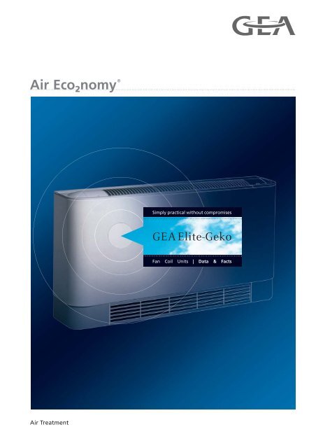
Simply practical without <strong>com</strong>promises<br />
<strong>GEA</strong> <strong>Elite</strong>-<strong>Geko</strong><br />
Fan Coil Units | Data & Facts<br />
Air Treatment
<strong>GEA</strong> <strong>Elite</strong>-<strong>Geko</strong><br />
Table of Contents<br />
Sizes ............................................................................................................................................. 3<br />
Components of Fan Coil Unit ..................................................................................................... 4<br />
Unit Selection ............................................................................................................................... 5<br />
Unit Description ........................................................................................................................... 6<br />
Description of Components ....................................................................................................... 6<br />
4-Pipe Chilled and Warm Water ......................................................................................................................... 8<br />
2-Pipe Chilled or Warm Water ......................................................................................................................... 10<br />
2-Pipe Warm Water .......................................................................................................................................... 12<br />
2-Pipe Chilled Water ........................................................................................................................................ 14<br />
Pressure Drop in Heat Exchanger ........................................................................................... 16<br />
Power and Current Consumption ............................................................................................ 17<br />
Acoustics ................................................................................................................................... 18<br />
Dimension of Basic Units without Casing .............................................................................. 19<br />
Dimensions of Casing and Accessories ................................................................................. 21<br />
Valves with Thermoelectric Actuators (230 V~) ..................................................................... 22<br />
Product Type Code .................................................................................................................... 23<br />
Copyright note<br />
Disclosing, copying, distributing or taking any action in reliance on the contents of this document is strictly prohibited without<br />
express prior consent. Violations entail liability for any damages or other liability arising. All rights in relation to patents,<br />
utility patents or design patents are reserved.<br />
2 PR-2009-0103-GB • Subject to modifications • Status 08/2009
<strong>GEA</strong> <strong>Elite</strong>-<strong>Geko</strong><br />
Sizes<br />
Size Width Air flow rate Sound pressure level 1<br />
•<br />
Heating capacity Q 2)<br />
H<br />
•<br />
Cooling capacity Q 2)<br />
K<br />
[mm] [m 3 /h] [dB(A)] [kW]<br />
1<br />
2<br />
3<br />
4<br />
977 200-490 25-47<br />
1127 350-940 27-53<br />
1277 400-1050 27-52<br />
1577 450-1120 28-53<br />
1.3-4,9<br />
1.4-2,6<br />
2.2-8,5<br />
2.4-4,4<br />
2.6-9,7<br />
2.7-5,0<br />
3.2-13,0<br />
3.4-7,2<br />
1) Ambient conditions refer to page 18 "Acoustics"<br />
2)<br />
Capacity data apply for input parameters: LPHW 70/50 °C, t L1 = +20 °C; chilled water 6/12 °C, t L1 = 27 °C, 46 % r.h.<br />
With other input parameters please contact your local <strong>GEA</strong> office.<br />
PR-2009-0103-GB • Subject to modifications • Status 08/2009 3
Fan Coil Unit Components<br />
For Wall and Ceiling Installation<br />
<strong>GEA</strong> <strong>Elite</strong>-<strong>Geko</strong><br />
1<br />
2<br />
3<br />
4<br />
14<br />
5<br />
6<br />
8<br />
15<br />
14<br />
7<br />
9<br />
13<br />
16<br />
12<br />
10<br />
10<br />
11<br />
Fig. 1:<br />
Unit <strong>com</strong>ponents (depending on unit configuration)<br />
Pos. 1:<br />
Pos. 2:<br />
Pos. 3:<br />
Pos. 4:<br />
Pos. 5:<br />
Pos. 6:<br />
Pos. 7:<br />
Pos. 8:<br />
Mounting panel<br />
Heat exchanger<br />
Terminal box<br />
Rear wall with lateral steel panels (basic casing)<br />
Filter element<br />
Main condensate tray<br />
Fan with casing<br />
Front panel (basic casing)<br />
Pos. 9: Access panel<br />
Pos. 10: Casing unit foot, right/left<br />
Pos. 11: Intake grille<br />
Pos. 12: Casing<br />
Pos. 13: Discharge grille<br />
Pos. 14: Unit foot (suction side), right/left<br />
Pos. 15: Lateral wall condensate tray<br />
Pos. 16: Lateral ceiling condensate tray<br />
4 PR-2009-0103-GB • Subject to modifications • Status 08/2009
Druckverluste im Wärmetauscher<br />
4 Rohrreihen Kühlen, 2-Leiter-System<br />
25<br />
1<br />
3<br />
2<br />
20<br />
15<br />
10<br />
9,0<br />
8,0<br />
7,0<br />
6,0<br />
5,0<br />
4,5<br />
4,0<br />
30<br />
3,5<br />
3,0<br />
2,5<br />
2,0<br />
1,5<br />
1,0<br />
0,9<br />
0,8<br />
0,7<br />
0,6<br />
0,5<br />
50<br />
60<br />
70<br />
80<br />
90<br />
1 0<br />
150<br />
2 0<br />
250<br />
3 0<br />
350<br />
4 0<br />
450<br />
5 0<br />
Wasservolumenstrom V W [l/h]<br />
6 0<br />
7 8 0<br />
9 0<br />
1 0<br />
Abb. 25.3<br />
<strong>GEA</strong> Top-<strong>Geko</strong> • ˜nderungen vorbehalten • Stand 08/00 (D) 25<br />
15 0<br />
2 0<br />
Unit Selection<br />
<strong>GEA</strong> <strong>Elite</strong>-<strong>Geko</strong><br />
Unit Description 6<br />
Recirculating<br />
air<br />
Cooling<br />
and<br />
Heating<br />
4-pipe Chilled and Warm Water 8<br />
Cooling or<br />
Heating<br />
2-pipe Chilled or Warm water 10<br />
Heating 2-pipe Warm Water 12<br />
Cooling 2-pipe Chilled Water 14<br />
DruckverlustDp [kPa]<br />
6 5 4 7<br />
Technical Data and Dimensions 16<br />
Valves 22<br />
PR-2009-0103-GB • Subject to modifications • Status 08/2009 5
Unit Description<br />
<strong>GEA</strong> <strong>Elite</strong>-<strong>Geko</strong><br />
Ceiling unit<br />
Wall unit<br />
Recirculating Air Units<br />
Heating/cooling/filtering<br />
2-/4-pipe system wall or ceiling<br />
mounting<br />
Basic construction made of<br />
sendzimir galvanized steel<br />
sheet with acoustic and thermal<br />
insulation made of polyethylene<br />
(electric and valve equipment<br />
depending on function and<br />
requirements)<br />
Fig. 2<br />
Unit casing<br />
with intake grille and plastic unit foot casing<br />
Front panel made of steel<br />
sheet<br />
colour white, similar RAL 9010<br />
Service panels and plastic<br />
discharge grille<br />
grey colour, similar RAL 7035<br />
additionally with<br />
Unit foot casing and plastic<br />
intake grille<br />
grey colour, similar RAL 7035<br />
Fig. 3<br />
Thermoelectric valves<br />
Valves<br />
(selection between loose or<br />
mounted delivery)<br />
2 and 3 way valves (2-point<br />
operation) with thermoelectric<br />
actuator<br />
Fig. 4<br />
Electric equipment<br />
Electric equipment<br />
terminal box<br />
(depending on requirements,<br />
configuration and unit functions)<br />
Fig. 5<br />
6 PR-2009-0103-GB • Subject to modifications • Status 08/2009
Unit Description<br />
<strong>GEA</strong> <strong>Elite</strong>-<strong>Geko</strong><br />
Heat exchanger<br />
for warm or chilled water<br />
Heat exchanger<br />
for warm and chilled water (4-pipe system)<br />
Copper pipes with drawn<br />
aluminium fins<br />
max. operating pressure 16 bar<br />
water as cooling medium<br />
50% glycol rate<br />
water as heating medium<br />
maximum inlet<br />
temperature 90 °C<br />
supplied with ½" connection,<br />
internal thread, air vent and drain<br />
Fig. 6<br />
Filter element<br />
Synthetic, washable filter<br />
medium, easy replacement,<br />
filter grade G1 (EN 779)<br />
Fig. 7<br />
Centrifugal fan 230 V ~ 50 Hz<br />
Single<br />
Tandem<br />
Centrifugal fan with low noise<br />
sleeve bearings, type and<br />
number of fans depend on unit<br />
size and selection, protection<br />
type IP32, insulation class B<br />
Fig. 8<br />
Lateral wall condensate tray<br />
Lateral ceiling condensate tray<br />
For collecting entire condensate<br />
of heat exchanger and valve<br />
piping, for condensate removal<br />
without pressure, made of plastic<br />
Fig. 9<br />
PR-2009-0103-GB • Subject to modifications • Status 08/2009 7
Recirculating Air Unit Heating and Cooling<br />
4-Pipe System Chilled and Warm Water<br />
Sizes 1 to 4<br />
CWP 6/12 °C<br />
t L1 = +27 °C<br />
ϕ 1 = 46 % r. h.<br />
LPHW 70/50 °C<br />
t L1 = +20 °C<br />
<strong>GEA</strong> <strong>Elite</strong>-<strong>Geko</strong><br />
Capacity stage 1 Capacity stage 2 Capacity stage 3<br />
Fan stage<br />
Air flow rate<br />
Cooling capacity<br />
Pressure drop<br />
Heating capacity<br />
Pressure drop<br />
Cooling capacity<br />
Pressure drop<br />
Heating capacity<br />
•<br />
Q K Δp K<br />
•<br />
Q H Δp H<br />
•<br />
Q K Δp K<br />
•<br />
Q H Δp H<br />
•<br />
Q K Δp K<br />
•<br />
Q H Δp H<br />
[m 3 /h] kW kPa kW kPa kW kPa kW kPa kW kPa kW kPa dB(A) dB(A)<br />
1 200 1.4 3.6 1.3 0.5 – – – – – – – – 33 25<br />
Pressure drop<br />
Cooling capacity<br />
Pressure drop<br />
Heating capacity<br />
Pressure drop<br />
Sound power<br />
Sound pressure *<br />
Size<br />
2 310 2.0 6.6 1.7 0.9 – – – – – – – – 44 35 1 Terminal box<br />
3 490 2.6 11.3 2.2 1.3 – – – – – – – – 56 47<br />
1 350 2.4 11.4 2.2 1.6 – – – – – – – – 36 27<br />
2 520 3.2 18.7 2.7 2.4 – – – – – – – – 46 38<br />
3 940 4.4 34.4 3.6 4.0 – – – – – – – – 62 53<br />
2<br />
1 380 – – – – 2.5 12.6 2.3 1.8 – – – – 38 29<br />
2 630 – – – – 3.5 22.9 2.9 2.8 – – – – 51 42 Speed<br />
<strong>com</strong>bination<br />
1, 2, 3 terminal<br />
3 940 – – – – 4.4 34.4 3.6 4.0 – – – – 62 53<br />
box<br />
1 400 2.7 5.7 2.6 2.7 – – – – – – – – 36 27<br />
2 590 3.6 9.5 3.2 3.9 – – – – – – – – 46 38<br />
3 1050 5.0 17.4 4.3 6.5 – – – – – – – – 61 52 K 0<br />
3<br />
1 440 – – – – 2.9 6.6 2.7 2.9 – – – – 39 31<br />
2 700 – – – – 3.9 11.4 3.5 4.6 – – – – 50 41<br />
3 1050 – – – – 5.0 17.4 4.3 6.5 – – – – 61 52<br />
1 450 3.4 10.8 3.2 5.2 – – – – – – – – 37 28<br />
2 750 4.9 21.0 4.4 8.9 – – – – – – – – 50 42<br />
3 1080 6.1 31.1 5.3 12.4 – – – – – – – – 61 53<br />
1 540 – – – – 3.9 13.7 3.6 6.3 – – – – 45 37<br />
Motor/<br />
TC<br />
Standard motor<br />
with integrated<br />
thermal<br />
contacts<br />
2 840 – – – – 5.3 23.7 4.6 9.7 – – – – 54 46<br />
4<br />
3 1080 – – – – 6.1 31.1 5.3 12.4 – – – – 61 53<br />
1 840 – – – – – – – – 5.3 23.7 4.6 9.7 54 46<br />
2 980 – – – – – – – – 5.7 27.9 5.0 11.3 58 50<br />
3 1080 – – – – – – – – 6.1 31.1 5.3 12.4 61 53<br />
1 2 3<br />
Capacity stage<br />
Medium<br />
connection **<br />
Wall<br />
Ceiling<br />
left 1<br />
right 2<br />
left 3<br />
right 4<br />
Order code<br />
G E . U W W . K 0<br />
* Ambient conditions refer to page 18 "Acoustics"<br />
** Front connection side, facing discharge<br />
8 PR-2009-0103-GB • Subject to modifications • Status 08/2009
<strong>GEA</strong> <strong>Elite</strong>-<strong>Geko</strong><br />
Accessories<br />
Accessories/Valves<br />
Recirculating Air Unit Heating and Cooling<br />
4-Pipe System Chilled and Warm Water<br />
Sizes 1 to 4<br />
Acce<br />
ssory<br />
class<br />
Accessory<br />
type<br />
Acce<br />
ssory<br />
class<br />
Accessory<br />
type<br />
Unit casing E 0 1 1<br />
Spare filter (1 set = 5 pieces) A 8 1 3<br />
Wall/ceiling mounting<br />
Wall/ceiling mounting<br />
Wall/ceiling mounting<br />
Unit casing with foot<br />
casing and plastic intake<br />
grille<br />
Unit foot<br />
(regardless of model<br />
size) *<br />
E 0 7 1<br />
A 9 1 3<br />
Sizes 1 to 4<br />
* 0, if irrespective of<br />
size Order code Z G E .<br />
Valves<br />
Heating circuit<br />
Cooling circuit<br />
k vs -values<br />
Actuator Operating voltage/circuit Cooling/Heating<br />
2-point<br />
open/close<br />
230 V AC T<br />
2 3<br />
1.60 ≡ 1 6<br />
4.00 ≡ 4 0<br />
Medium connection left<br />
Medium connection right<br />
L<br />
R<br />
k vs value as given above<br />
Cooling<br />
Heating<br />
Connection/<br />
shut-off<br />
0<br />
Order code<br />
V G E . T T . 0<br />
Cooling circuit<br />
Heating circuit<br />
PR-2009-0103-GB • Subject to modifications • Status 08/2009 9
Recirculating Air Unit Heating or Cooling<br />
2-Pipe System Chilled or Warm Water<br />
Sizes 1 to 4<br />
CWP 6/12 °C<br />
t L1 = +27 °C<br />
ϕ 1 = 46 % r.h.<br />
LPHW 70/50 °C<br />
t L1 = +20 °C<br />
<strong>GEA</strong> <strong>Elite</strong>-<strong>Geko</strong><br />
Capacity stage 1 Capacity stage 2 Capacity stage 3<br />
Fan stage<br />
Air flow rate<br />
Cooling capacity<br />
Pressure drop<br />
Heating capacity<br />
Pressure drop<br />
Cooling capacity<br />
Pressure drop<br />
Heating capacity<br />
•<br />
Q K Δp K<br />
•<br />
Q H Δp H<br />
•<br />
Q K Δp K<br />
•<br />
Q H Δp H<br />
•<br />
Q K Δp K<br />
•<br />
Q H Δp H<br />
[m 3 /h] kW kPa kW kPa kW kPa kW kPa kW kPa kW kPa dB(A) dB(A)<br />
1 200 1.4 3.6 2.6 1.0 – – – – – – – – 33 25<br />
Pressure drop<br />
Cooling capacity<br />
Pressure drop<br />
Heating capacity<br />
Pressure drop<br />
Sound power<br />
Sound pressure *<br />
Size<br />
2 310 2.0 6.6 3.6 1.9 – – – – – – – – 44 35 1 Terminal box<br />
3 490 2.6 11.3 4.9 3.4 – – – – – – – – 56 47<br />
1 350 2.4 11.4 4.3 3.2 – – – – – – – – 36 27<br />
2 520 3.2 18.7 5.7 5.3 – – – – – – – – 46 38<br />
3 940 4.4 34.4 8.5 10.9 – – – – – – – – 62 53<br />
2<br />
1 380 – – – – 2.5 12.6 4.6 3.5 – – – – 38 29<br />
2 630 – – – – 3.5 22.9 6.5 6.7 – – – – 51 42 Speed<br />
<strong>com</strong>bination<br />
1, 2, 3 terminal<br />
3 940 – – – – 4.4 34.4 8.5 10.9 – – – – 62 53<br />
box<br />
1 400 2.7 5.7 5.0 1.6 – – – – – – – – 36 27<br />
2 590 3.6 9.5 6.5 2.7 – – – – – – – – 46 38<br />
3 1050 5.0 17.4 9.7 5.6 – – – – – – – – 61 52 K 0<br />
3<br />
1 440 – – – – 2.9 6.6 5.3 1.8 – – – – 39 31<br />
2 700 – – – – 3.9 11.4 7.4 3.4 – – – – 50 41<br />
3 1050 – – – – 5.0 17.4 9.7 5.6 – – – – 61 52<br />
1 450 3.4 10.8 5.9 2.8 – – – – – – – – 37 28<br />
2 750 4.9 21.0 8.8 5.7 – – – – – – – – 50 42<br />
3 1120 6.2 32.3 11.5 9.4 – – – – – – – – 61 53<br />
1 540 – – – – 4.4 10.3 7.6 2.6 – – – – 45 37<br />
Motor/<br />
TC<br />
Standard motor<br />
with integrated<br />
thermal<br />
contacts<br />
2 840 – – – – 6.1 18.4 10.8 4.9 – – – – 54 46<br />
4<br />
3 1080 – – – – 7.2 25.1 13.0 6.9 – – – – 61 53<br />
1 840 – – – – – – – – 6.1 18.4 10.8 4.9 54 46<br />
2 980 – – – – – – – – 6.7 22.0 12.2 6.1 58 50<br />
3 1080 – – – – – – – – 7.2 25.1 13.0 6.9 61 53<br />
1 2 3<br />
Capacity stage<br />
Medium<br />
connection **<br />
Wall<br />
Ceiling<br />
left 1<br />
right 2<br />
left 3<br />
right 4<br />
Order code<br />
G E . U W C . K 0<br />
* Ambient conditions refer to. page 18 "Acoustics"<br />
** Front connection side, facing discharge<br />
10 PR-2009-0103-GB • Subject to modifications • Status 08/2009
<strong>GEA</strong> <strong>Elite</strong>-<strong>Geko</strong><br />
Accessories<br />
Accessories/Valves<br />
Recirculating Air Unit Heating or Cooling<br />
2-Pipe System Chilled or Warm Water<br />
Sizes 1 to 4<br />
Wall/ceiling mounting<br />
Acce<br />
ssory<br />
class<br />
Accessory<br />
type<br />
Unit casing E 0 1 1<br />
Acce<br />
ssory<br />
class<br />
Accessory<br />
type<br />
hörtyp<br />
Spare filter (1 set = 5 pieces) A 8 1 3<br />
Wall/ceiling mounting<br />
Unit casing with foot<br />
casing and plastic intake<br />
grille<br />
E 0 7 1<br />
Wall/ceiling mounting<br />
Unit foot (regardless of<br />
model size) *<br />
A 9 1 3<br />
Sizes 1 to 4<br />
* 0, if irrespective of<br />
size Order code Z G E .<br />
Valves<br />
Actuator Operating voltage/circuit Heating circuit/<br />
cooling circuit<br />
2-point<br />
open/close<br />
230 V AC T<br />
k vs -values<br />
Cooling/Heating<br />
Medium connection left L<br />
1.60 ≡ 1 6 Medium connection right R<br />
3 4.00 ≡ 4 0<br />
k vs value as given above<br />
Cooling/Heating<br />
Connection/<br />
shut-off<br />
0<br />
Order code<br />
V G E . T 3 . 0<br />
Cooling/heating circuit<br />
PR-2009-0103-GB • Subject to modifications • Status 08/2009 11
Recirculating Air Unit Heating<br />
2-pipe chilled and warm water<br />
Sizes 1 to 4<br />
LPHW 70/50 °C<br />
t L1 = +20 °C<br />
<strong>GEA</strong> <strong>Elite</strong>-<strong>Geko</strong><br />
Capacity stage 1 Capacity stage 2 Capacity stage 3<br />
Fan stage<br />
Air flow rate<br />
Heating capacity<br />
Pressure drop<br />
Heating capacity<br />
Pressure drop<br />
•<br />
Q H Δp H<br />
•<br />
Q H Δp H<br />
•<br />
Q H Δp H<br />
[m 3 /h] kW kPa kW kPa kW kPa dB(A) dB(A)<br />
1 200 2.6 1.0 – – – – 33 25<br />
Heating capacity<br />
Pressure drop<br />
Sound power<br />
Sound pressure *<br />
Size<br />
2 310 3.6 1.9 – – – – 44 35 1 Terminal box<br />
3 490 4.9 3.4 – – – – 56 47<br />
1 350 4.3 3.2 – – – – 36 27<br />
2 520 5.7 5.3 – – – – 46 38<br />
3 940 8.5 10.9 – – – – 62 53<br />
2<br />
1 380 – – 4.6 3.5 – – 38 29<br />
2 630 – – 6.5 6.7 – – 51 42 Speed<br />
<strong>com</strong>bination<br />
1, 2, 3 terminal<br />
3 940 – – 8.5 10.9 – – 62 53<br />
box<br />
1 400 5.0 1.6 – – – – 36 27<br />
2 590 6.5 2.7 – – – – 46 38<br />
3 1050 9.7 5.6 – – – – 61 52 K 0<br />
3<br />
1 440 – – 5.3 1.8 – – 39 31<br />
2 700 – – 7.4 3.4 – – 50 41<br />
3 1050 – – 9.7 5.6 – – 61 52<br />
1 450 5.9 2.8 – – – – 37 28<br />
2 750 8.8 5.7 – – – – 50 42<br />
3 1120 11.5 9.4 – – – – 61 53<br />
1 540 – – 7.6 2.6 – – 45 37<br />
Motor/<br />
TC Standard<br />
motor with integrated<br />
thermal<br />
contacts<br />
2 840 – – 10.8 4.9 – – 54 46<br />
4<br />
3 1080 – – 13.0 6.9 – – 61 53<br />
1 840 – – – – 10.8 4.9 54 46<br />
2 980 – – – – 12.2 6.1 58 50<br />
3 1080 – – – – 13.0 6.9 61 53<br />
1 2 3<br />
Capacity stage<br />
Medium<br />
connection **<br />
Wall<br />
Ceiling<br />
left 1<br />
right 2<br />
left 3<br />
right 4<br />
Order code<br />
G E . U 0 W . K 0<br />
* Ambient conditions refer to. page 18 "Acoustics"<br />
** Front connection side, facing discharge<br />
12 PR-2009-0103-GB • Subject to modifications • Status 08/2009
<strong>GEA</strong> <strong>Elite</strong>-<strong>Geko</strong><br />
Accessories/Valves<br />
Recirculating Air Unit Heating<br />
2-Pipe Warm Water, Model Sizes 1 to 4<br />
Accessories<br />
Acce<br />
ssory<br />
class<br />
Accessory<br />
type<br />
Acce<br />
ssory<br />
class<br />
Accessory<br />
type<br />
Unit casing E 0 1 1<br />
Spare filter (1 set = 5 pieces) A 8 1 3<br />
Wall/ceiling mounting<br />
Wall/ceiling mounting<br />
Unit casing with foot<br />
casing and plastic intake<br />
grille<br />
E 0 7 1<br />
Wall/ceiling mounting<br />
Unit foot (regardless of<br />
model size) *<br />
A 9 1 3<br />
Sizes 1 to 4<br />
* 0, if irrespective<br />
of size Order code Z G E .<br />
Valves<br />
Heating circuit<br />
k vs -values<br />
Actuator Operating voltage/circuit Heating<br />
2-point<br />
open/close<br />
230 V AC T<br />
2 3<br />
1.60 ≡ 1 6<br />
4.00 ≡ 4 0<br />
Medium connection left<br />
Medium connection right<br />
L<br />
R<br />
k vs value as given above<br />
Heating<br />
Connection/<br />
shut-off<br />
0<br />
Order code<br />
V G E T . 0<br />
PR-2009-0103-GB • Subject to modifications • Status 08/2009 13
Recirculating Air Unit Cooling<br />
2-Pipe System Chilled Water<br />
Sizes 1 to 4<br />
Chilled water<br />
6/12 °C<br />
t L1 = +27 °C<br />
ϕ 1 = 46 % r.h.<br />
<strong>GEA</strong> <strong>Elite</strong>-<strong>Geko</strong><br />
Capacity stage 1 Capacity stage 2 Capacity stage 3<br />
Fan stage<br />
Air flow rate<br />
Cooling capacity<br />
Pressure drop<br />
Cooling capacity<br />
•<br />
Q K Δp K<br />
•<br />
Q K Δp K<br />
•<br />
Q K Δp K<br />
[m 3 /h] kW kPa kW kPa kW kPa dB(A) dB(A)<br />
1 200 1.4 3.6 – – – – 33 25<br />
Pressure drop<br />
Cooling capacity<br />
Pressure drop<br />
Sound power<br />
Sound pressure *<br />
Size<br />
2 310 2.0 6.6 – – – – 44 35 1 Terminal box<br />
3 490 2.6 11.3 – – – – 56 47<br />
1 350 2.4 11.4 – – – – 36 27<br />
2 520 3.2 18.7 – – – – 46 38<br />
3 940 4.4 34.4 – – – – 62 53<br />
2<br />
1 380 – – 2.5 12.6 – – 38 29<br />
2 630 – – 3.5 22.9 – – 51 42 Speed<br />
<strong>com</strong>bination<br />
1, 2, 3 terminal<br />
3 940 – – 4.4 34.4 – – 62 53<br />
box<br />
1 400 2.7 5.7 – – – – 36 27<br />
2 590 3.6 9.5 – – – – 46 38<br />
3 1050 5.0 17.4 – – – – 61 52 K 0<br />
3<br />
1 440 – – 2.9 6.6 – – 39 31<br />
2 700 – – 3.9 11.4 – – 50 41<br />
3 1050 – – 5.0 17.4 – – 61 52<br />
1 450 3.4 10.8 – – – – 37 28<br />
2 750 4.9 21.0 – – – – 50 42<br />
3 1120 6.2 32.3 – – – – 61 53<br />
1 540 – – 4.4 10.3 – – 45 37<br />
Motor/<br />
TC<br />
Standard motor<br />
with integrated<br />
thermal<br />
contacts<br />
2 840 – – 6.1 18.4 – – 54 46<br />
4<br />
3 1080 – – 7.2 25.1 – – 61 53<br />
1 840 – – – – 6.1 18.4 54 46<br />
2 980 – – – – 6.7 22.0 58 50<br />
3 1080 – – – – 7.2 25.1 61 53<br />
1 2 3<br />
Capacity stage<br />
Medium<br />
connection **<br />
Wall<br />
Ceiling<br />
left 1<br />
right 2<br />
left 3<br />
right 4<br />
Order code<br />
G E . U W 0 . K 0<br />
* Ambient conditions refer to. page 18 "Acoustics"<br />
** Front connection side, facing discharge<br />
14 PR-2009-0103-GB • Subject to modifications • Status 08/2009
<strong>GEA</strong> <strong>Elite</strong>-<strong>Geko</strong><br />
Accessories/Valves<br />
Recirculating Air Unit Cooling<br />
2-Pipe System Chilled Water, Model Sizes 1 to 4<br />
Accessories<br />
Acce<br />
ssory<br />
class<br />
Accessory<br />
type<br />
Acce<br />
ssory<br />
class<br />
Accessory<br />
type<br />
Unit casing E 0 1 1<br />
Spare filter (1 set = 5 pieces) A 8 1 3<br />
Wall/ceiling mounting<br />
Wall/ceiling mounting<br />
Unit casing with foot<br />
casing and plastic intake<br />
grille<br />
E 0 7 1<br />
Wall/ceiling mounting<br />
Unit foot (regardless of<br />
model size) *<br />
A 9 1 3<br />
Sizes 1 to 4<br />
* 0, if irrespective of<br />
size Order code Z G E .<br />
Valves<br />
Cooling circuit<br />
k vs -values<br />
Actuator Operating voltage/circuit Cooling Medium connection left L<br />
2-point<br />
open/close<br />
230 V AC T<br />
2 3<br />
1.60 ≡ 1 6 Medium connection right R<br />
4.00 ≡ 4 0<br />
k vs value as given above<br />
Cooling<br />
Connection/<br />
shut-off<br />
0<br />
Order code<br />
V G E . T . 0<br />
PR-2009-0103-GB • Subject to modifications • Status 08/2009 15
Pressure Prop in Heat Exchanger<br />
for Warm and Chilled Water<br />
<strong>GEA</strong> <strong>Elite</strong>-<strong>Geko</strong><br />
Cooling in 2-pipe system<br />
Heating in 2-pipe system<br />
25<br />
25<br />
20<br />
15<br />
Size/CS*<br />
2/1<br />
2/2<br />
1/1<br />
4/1<br />
3/1<br />
3/2<br />
4/2<br />
4/3<br />
20<br />
15<br />
Size/CS*<br />
2/1<br />
2/2<br />
1/1<br />
4/1<br />
3/1<br />
3/2<br />
4/2<br />
4/3<br />
Pressure drop [kPa]<br />
10<br />
9,0<br />
8,0<br />
7,0<br />
6,0<br />
5,0<br />
4,5<br />
4,0<br />
3,5<br />
3,0<br />
2,5<br />
2,0<br />
Pressure drop [kPa]<br />
10<br />
9,0<br />
8,0<br />
7,0<br />
6,0<br />
5,0<br />
4,5<br />
4,0<br />
3,5<br />
3,0<br />
2,5<br />
2,0<br />
1,5<br />
1,5<br />
1,0<br />
0,9<br />
0,8<br />
0,7<br />
0,6<br />
1,0<br />
0,9<br />
0,8<br />
0,7<br />
0,6<br />
0,5<br />
0,5<br />
50<br />
60<br />
70<br />
80<br />
100<br />
90<br />
150<br />
200<br />
250<br />
300<br />
350<br />
400<br />
450<br />
500<br />
600<br />
700<br />
800<br />
900<br />
Water flow rate V<br />
• w [l/h]<br />
1000<br />
1500<br />
2000<br />
50<br />
60<br />
70<br />
80<br />
100<br />
90<br />
150<br />
200<br />
250<br />
300<br />
350<br />
400<br />
450<br />
500<br />
•<br />
Water flow rate V w [l/h]<br />
600<br />
700<br />
800<br />
900<br />
1000<br />
1500<br />
2000<br />
Cooling in 4-pipe system<br />
Heating in 4-pipe system<br />
25<br />
25<br />
4/1<br />
4/1<br />
20<br />
Size/CS*<br />
2/1<br />
4/2<br />
20 Size/CS* 4/2<br />
1/1<br />
2/2<br />
4/3<br />
4/3<br />
2/1<br />
15<br />
1/1<br />
3/1<br />
15<br />
3/1 2/2<br />
3/2<br />
3/2<br />
Pressure drop [kPa]<br />
10<br />
9,0<br />
8,0<br />
7,0<br />
6,0<br />
5,0<br />
4,5<br />
4,0<br />
3,5<br />
3,0<br />
2,5<br />
2,0<br />
Pressure drop [kPa]<br />
10<br />
9,0<br />
8,0<br />
7,0<br />
6,0<br />
5,0<br />
4,5<br />
4,0<br />
3,5<br />
3,0<br />
2,5<br />
2,0<br />
1,5<br />
1,5<br />
1,0<br />
0,9<br />
0,8<br />
0,7<br />
0,6<br />
1,0<br />
0,9<br />
0,8<br />
0,7<br />
0,6<br />
0,5<br />
0,5<br />
50<br />
60<br />
70<br />
80<br />
90<br />
100<br />
150<br />
200<br />
250<br />
300<br />
350<br />
400<br />
450<br />
500<br />
600<br />
700<br />
800<br />
900<br />
Water flow rate V<br />
• w [l/h]<br />
1000<br />
1500<br />
2000<br />
50<br />
60<br />
70<br />
80<br />
90<br />
100<br />
150<br />
200<br />
250<br />
300<br />
350<br />
400<br />
450<br />
500<br />
•<br />
Water flow rate V w [l/h]<br />
600<br />
700<br />
800<br />
900<br />
1000<br />
1500<br />
2000<br />
Fig. 10<br />
* Size, CS = Capacity stage<br />
16 PR-2009-0103-GB • Subject to modifications • Status 08/2009
Maximum Power and Current Consumption<br />
<strong>GEA</strong> <strong>Elite</strong>-<strong>Geko</strong><br />
Maximum Power and Current Consumption<br />
Size<br />
Speed<br />
Air flow rate<br />
[m 3 /h]<br />
Capacity stage 1 Capacity stage 2 Capacity stage 3<br />
Capacity [W]<br />
Current [A] Capacity [W] Current [A] Capacity [W] Current [A]<br />
1 200 15 0.15 – – – –<br />
1<br />
2 310 28 0.19 – – – –<br />
3 490 58 0.27 – – – –<br />
1 350 30 0.31 – – – –<br />
2 520 52 0.40 – – – –<br />
2<br />
3 940 133 0.61 – – – –<br />
1 380 – – 34 0.32 – –<br />
2 630 – – 63 0.46 – –<br />
3 940 – – 133 0.61 – –<br />
1 400 33 0.32 – – – –<br />
2 590 56 0.42 – – – –<br />
3<br />
3 1050 137 0.62 – – – –<br />
1 440 – – 39 0.36 – –<br />
2 700 – – 72 0.46 – –<br />
3 1050 – – 137 0.62 – –<br />
1 450 35 0.34 – – – –<br />
2 750 77 0.49 – – – –<br />
3 1120 142 0.65 – – – –<br />
1 540 – – 52 0.38 – –<br />
4<br />
2 840 – – 89 0.51 – –<br />
3 1080 – – 140 0.63 – –<br />
1 840 – – – – 89 0.51<br />
2 980 – – – – 117 0.59<br />
3 1080 – – – – 140 0.63<br />
PR-2009-0103-GB • Subject to modifications • Status 08/2009 17
Acoustics<br />
<strong>GEA</strong> <strong>Elite</strong>-<strong>Geko</strong><br />
Size<br />
Capacity stage<br />
Speed<br />
Air flow rate<br />
Sound power level (dB) Sound pressure level *<br />
Octave centre frequency [Hz]<br />
Sum level<br />
unrated<br />
rated<br />
Rated according to<br />
m 3 /h 63 125 250 500 1000 2000 4000 8000 [dB] dB(A) dB(A) NR NC<br />
1 200 36 36 38 32 25 < 20 < 20 < 20 42 33 25 19 17<br />
1 1<br />
2 310 35 42 46 42 39 33 24 < 20 49 44 35 30 29<br />
3 490 43 52 56 53 51 48 42 34 60 56 47 42 41<br />
1 350 43 36 39 36 27 < 20 < 20 < 20 46 36 27 24 21<br />
1<br />
2 520 41 43 48 46 40 33 22 < 20 52 46 38 34 32<br />
2<br />
3 940 50 57 60 60 57 53 46 37 65 62 53 48 47<br />
1 380 37 35 41 38 31 22 < 20 < 20 45 38 29 26 23<br />
2<br />
2 630 40 44 52 51 45 38 26 20 56 51 42 39 37<br />
3 940 50 57 60 60 57 53 46 37 65 62 53 48 47<br />
1 400 42 34 40 35 27 < 20 < 20 < 20 45 36 27 23 20<br />
1<br />
2 590 38 41 47 46 41 34 23 < 20 51 46 38 34 32<br />
3<br />
3 1050 47 58 60 59 56 52 45 36 65 61 52 47 46<br />
1 440 36 37 43 39 32 24 < 20 < 20 46 39 31 27 24<br />
2<br />
2 700 42 46 51 49 45 40 30 21 55 50 41 37 35<br />
3 1050 47 58 60 59 56 52 45 36 65 61 52 47 46<br />
1 450 34 35 42 35 29 20 < 20 < 20 44 37 28 23 21<br />
1<br />
2 750 39 45 52 49 45 40 30 22 55 50 42 37 35<br />
4<br />
2<br />
3<br />
3 1120 48 57 62 58 57 53 47 39 66 61 53 48 37<br />
1 540 37 42 47 44 41 33 22 < 20 50 45 37 32 31<br />
2 840 50 48 55 53 48 46 36 27 59 54 46 41 40<br />
3 1080 49 56 61 59 56 54 46 39 65 61 52 57 55<br />
1 840 50 48 55 53 48 46 36 27 59 54 46 41 40<br />
2 980 48 53 59 56 53 51 42 33 63 58 50 45 43<br />
3 1080 49 56 61 59 56 54 46 39 65 61 53 48 46<br />
*) Sound pressure level relates to a reverberation field of a 100 m 3 room and reverberation time of 0,5 s<br />
18 PR-2009-0103-GB • Subject to modifications • Status 08/2009
Dimensions of Basic Units without Casing<br />
<strong>GEA</strong> <strong>Elite</strong>-<strong>Geko</strong><br />
Unit for ceiling installation<br />
Lateral condensate tray for ceiling cooling units<br />
Fig. 11 Fig. 12<br />
Unit for wall installation<br />
Lateral condensate tray for wall cooling units<br />
Fig. 13 Fig. 14<br />
Mounting dimensions wall<br />
Mounting dimensions ceiling<br />
Fig. 15 Fig. 16<br />
Dimension and weight<br />
(For order number refer to the Product Type Code)<br />
Size Weight b [mm]<br />
[kg]*<br />
1 32 614<br />
2 40 764<br />
3 43 914<br />
4 48 1214<br />
* Basic unit including<br />
unit casing<br />
Unit dimensions presented in the graphs above are<br />
independent of the unit model size.<br />
Unit length and weight vary depending on the model size and<br />
can be found in the table to the left.<br />
PR-2009-0103-GB • Subject to modifications • Status 08/2009 19
Dimensions of Basic Units without Casing<br />
<strong>GEA</strong> <strong>Elite</strong>-<strong>Geko</strong><br />
Dimensions for field-provided ducts on suction and<br />
discharge side<br />
Dimensions for service purposes with mounting behind<br />
on site field-provided casing<br />
450<br />
227<br />
97 84<br />
412<br />
ø 16<br />
Fig. 17 Fig. 18<br />
Medium connections (warm/chilled water)<br />
Medium connections (warm/chilled water)<br />
2-pipe system for wall and ceiling installation<br />
Heat exchanger for capacity size 1 and 2,<br />
½" internal thread<br />
1 Filter removal direction<br />
Heat exchanger content<br />
Size CS1 (l) CS 2 (l) CS 3 (l)<br />
1 1.1 1.1 –<br />
2 1.4 1.4 –<br />
3 1.7 1.7 –<br />
4 2.2 2.9 2.9<br />
4-pipe system for wall and ceiling installation<br />
Heat exchanger with heating and cooling circuit,<br />
½" internal thread<br />
1 Filter removal direction<br />
2 Heating<br />
3 Cooling<br />
Heat exchanger content<br />
Size Cooling circuit (l) Heating<br />
CS1 CS2 CS3 circuit (l)<br />
1 1.1 1.1 – 0.3<br />
2 1.4 1.4 – 0.4<br />
3 1.7 1.7 – 0.5<br />
4 2.2 2.2 2.2 0.8<br />
Fig. 19 Fig. 20<br />
20 PR-2009-0103-GB • Subject to modifications • Status 08/2009
Dimensions of Casing and Accessories<br />
<strong>GEA</strong> <strong>Elite</strong>-<strong>Geko</strong><br />
Unit casing white colour; similar RAL 9010<br />
with discharge grille grey colour; similar RAL 7035<br />
(wall and ceiling installation)<br />
Size Order-Nr. Weight [kg]<br />
1 ZGE.1E011 8.4<br />
2 ZGE.2E011 9.5<br />
3 ZGE.3E011 10.3<br />
4 ZGE.4E011 12.6<br />
* including grille<br />
Fig. 21<br />
Unit casing<br />
white colour, similar RAL 9010 with discharge grille,<br />
intake grille and casing unit foot<br />
Grey colour, similar RAL 7035 made of plastic<br />
Size Order-Nr. Weight [kg]<br />
1 ZGE.1E071 8.8<br />
2 ZGE.2E071 10.0<br />
3 ZGE.3E071 10.8<br />
4 ZGE.4E071 13.2<br />
Fig. 22<br />
Unit foot (on intake side)<br />
(1 set = 2 pieces)<br />
Size Order-Nr. Weight [kg]<br />
1-4 ZGE.0A913 0.26<br />
Fig. 23<br />
Spare filter set (1 set = 5 pieces)<br />
filter grade G1 (EN 779)<br />
regenerative filter medium<br />
Size Order-Nr. Weight [kg]<br />
1 ZGE.1A813 0.26<br />
2 ZGE.2A813 0.34<br />
3 ZGE.3A813 0.37<br />
4 ZGE.4A813 0.43<br />
Fig. 24<br />
Size 1 2 3 4<br />
L [mm] 977 1127 1277 1577<br />
PR-2009-0103-GB • Subject to modifications • Status 08/2009 21
Valves<br />
Valves with Thermoelectric Actuators (230 V~)<br />
<strong>GEA</strong> <strong>Elite</strong>-<strong>Geko</strong><br />
Thermoelectric valve actuators<br />
– Plastic actuator casing<br />
Technical data:<br />
Function type<br />
T<br />
Control type<br />
2-point (modulating)<br />
Operating voltage<br />
230 V AC<br />
50/60 Hz<br />
Power consumption [W] 3<br />
Heat up current [A] 0.6<br />
Rated current [A] 0.014<br />
Type of protection<br />
IP44<br />
Run time (approx.) [min] 2.5<br />
Operating force [N]<br />
90 N<br />
Control stroke [mm] 4<br />
Max. allowed ambient temp. 50 °C<br />
Connecting cable [m] 1<br />
Fig. 25<br />
Two and three way valves<br />
– Brass or red brass valve body<br />
– Stainless steel spindle and cone<br />
Technical data:<br />
Rated pressure<br />
16 bar<br />
max. medium temperature 120 °C<br />
max. glycol concentration 50 %<br />
Rated dimensions<br />
[mm]<br />
Stroke 2,5<br />
mm<br />
a b c d e<br />
G 1/2" A<br />
G 3/4" A<br />
56<br />
66<br />
40<br />
40<br />
34.5<br />
36.6<br />
5<br />
5<br />
Fig. 26<br />
The regulation valves are mounted by others on site,<br />
i.e. with piping and wired.<br />
Three valve valves:<br />
DN<br />
k VS A-AB<br />
[m 3 /h]<br />
k VS B-AB<br />
[m 3 /h]<br />
Valve external<br />
thread<br />
Dp max<br />
[kPa]<br />
Order-Nr.<br />
15 1.6 1.0 G 1/2" A 200 VGE.T316.0#<br />
20 4.0 2.5 G 3/4" A 100 VGE.T340.0#<br />
Pressure drop Δp [kPa]<br />
Fig. 27<br />
•<br />
Water flow rate V [l/h]<br />
Two valve valves:<br />
DN<br />
k VS A-AB<br />
[m 3 /h]<br />
Valve external<br />
thread<br />
Dp max<br />
[kPa]<br />
Order-Nr.<br />
15 1.6 G 1/2" A 300 VGE.T216.0#<br />
20 4.0 G 3/4" A 100 VGE.T240.0#<br />
With mounted valves for a 4-pipe system the order<br />
number must be specified with k vs value and number of<br />
ways of heating valve, e.g. VGE.T340T216.0# (see<br />
Product Type Code on page 23).<br />
The symbol "#" is reserved for medium connection left<br />
(L) or right (R).<br />
Note: The max. pressure drop in heat exchanger with<br />
fully open valve should not exceed 25 kPa in cooling<br />
mode and 20 kPa in heating mode.<br />
22 PR-2009-0103-GB • Subject to modifications • Status 08/2009
Product Type Code<br />
<strong>GEA</strong> <strong>Elite</strong>-<strong>Geko</strong><br />
Unit Type Code<br />
Valve Code<br />
G E 1 1 . U 0 W 1 . K 0 V G E . T 3 4 0 T 2 1 6 . 0 L<br />
Cooling/heating<br />
Heating circuit<br />
Size<br />
1 = Size 1<br />
2 = Size 2<br />
3 = Size 3<br />
4 = Size 4<br />
Capacity stage<br />
1 = Capacity stage 1<br />
2 = Capacity stage 2<br />
3 = Capacity stage 3<br />
Function type<br />
T = 2-point 230 V<br />
Valve body<br />
2 = 2-way<br />
3 = 3-way<br />
K vs -value<br />
16 = Kvs-value 1,6<br />
40 = K vs -value 4,0<br />
Air flow function<br />
U = Circulating air<br />
Medium related function<br />
Heating only<br />
0W = Warm water pump<br />
Cooling only<br />
W0 = Chilled water pump<br />
Cooling or heating<br />
WC = WWP(LPHW) - CWP<br />
Cooling and heating<br />
Warm<br />
water<br />
= WWP(LPHW) - CWP<br />
Connection<br />
0 = Inlet/outlet with external thread<br />
Medium connection<br />
L = left<br />
R = right<br />
Medium connection *<br />
Wall<br />
1 = left<br />
2 = right<br />
Ceiling<br />
3 = left<br />
4 = right<br />
Fan<br />
Terminal box with terminal strip<br />
K = Speed stages 1, 2, 3<br />
Motor/TC<br />
0 = Standard motor with integrated thermal contacts<br />
* Front connection side, facing discharge<br />
PR-2009-0103-GB • Subject to modifications • Status 08/2009 23
Customer proximity, sales structures<br />
Reachable always and everywhere!<br />
A<br />
B<br />
BG<br />
BIH<br />
BY<br />
CH<br />
CZ<br />
CZ<br />
D<br />
D<br />
<strong>GEA</strong> Klimatechnik<br />
GmbH & Co KG<br />
A-4673 Gaspoltshofen<br />
Tel. +43 / 7735 / 8000-0<br />
<strong>GEA</strong> Happel Belgium N. V.<br />
B-1130 Brussels<br />
Tel. +32 / 2 / 2406161<br />
EVISS Ltd.<br />
BG-7000 Rousse<br />
Tel . +359 / 82 / 81000<br />
<strong>GEA</strong> Klimatechnik<br />
GmbH & Co KG<br />
RS-11070 Novi Beograd<br />
Tel. +381 / 11 / 3193955<br />
<strong>GEA</strong> Klimatechnik UAB<br />
LT-01141 Vilnius<br />
Tel. +370 / 5 / 2106060<br />
ATC Klimatec Schweiz AG<br />
CH-3065 Bolligen<br />
Tel. +41 / 31 / 9171919<br />
<strong>GEA</strong> LVZ, a.s.<br />
CZ-46312 Liberec<br />
Tel. +420 / 48 / 5225-111<br />
<strong>GEA</strong> Klimatizace spol. s r.o.<br />
CZ-46312 Liberec<br />
Tel. +420 / 48 / 5225-303<br />
<strong>GEA</strong> Happel<br />
Klimatechnik GmbH<br />
D-44625 Herne<br />
Tel. +49 / 2325 / 468-00<br />
<strong>GEA</strong> Happel<br />
Wieland GmbH<br />
D-44625 Herne<br />
Tel. +49 / 2325 / 468-754<br />
D<br />
D<br />
D<br />
DK<br />
E<br />
EST<br />
F<br />
F<br />
FIN<br />
GB<br />
<strong>GEA</strong> Deichmann<br />
Umwelttechnik GmbH<br />
D-36179 Bebra<br />
Tel. +49 / 6622 / 504-0<br />
<strong>GEA</strong> Delbag<br />
Lufttechnik GmbH<br />
D-44625 Herne<br />
Tel. +49 / 2325 / 468-700<br />
<strong>GEA</strong> Delbag-Luftfilter<br />
Vertriebsgesellschaft mbH<br />
D-10709 Berlin<br />
Tel. +49 / 30 / 43592-3<br />
CS Klimateknik ApS<br />
DK-5450 Otterup<br />
Tel . +45 / 38 / 887070<br />
<strong>GEA</strong> Air Treatment<br />
Marketing Services Int.<br />
GmbH – oficina España<br />
ES-28028 Madrid<br />
Tel. +34 / 91 / 3837701<br />
<strong>GEA</strong> Klimatechnik UAB<br />
LT-01141 Vilnius<br />
Tel. +370 / 5 / 2106060<br />
<strong>GEA</strong> Delbag<br />
Filtration de l‘air<br />
F-77450 Montry<br />
Tel. +33 / 1 / 60043355<br />
<strong>GEA</strong> Happel France sarl<br />
F-59436 Roncq Cedex<br />
Tel. +33 / 3 / 20689020<br />
OY TEKNOCALOR AB<br />
FIN-01300 Vantaa<br />
Tel. +358 / 10 / 8201100<br />
<strong>GEA</strong> Denco Ltd.<br />
UK-HR4 8DS Hereford<br />
Tel. +44 / 1432 / 277 277<br />
H<br />
HR<br />
IE<br />
IS<br />
L<br />
LT<br />
LV<br />
MWE<br />
N<br />
NL<br />
P<br />
<strong>GEA</strong> Klimatechnika Kft<br />
H-1037 Budapest<br />
Tel. +36 / 1 / 4393200<br />
<strong>GEA</strong> Klima-rashladna<br />
tehnika d.o.o.<br />
HR-10000 Zagreb<br />
Tel. +385 / 1 / 6064900<br />
Aspect Environmental Ltd.<br />
Ardee, Co. Louth Ireland<br />
Tel. +353 / 41 / 6858983<br />
Rafn Jensson<br />
IS-110 Reykjavik<br />
Tel. +354 / 56 / 780-30<br />
<strong>GEA</strong> Happel Luxembourg<br />
L-4940 Bascharage<br />
Tel. +352 / 26 / 502970<br />
<strong>GEA</strong> Klimatechnik UAB<br />
LT-01141 Vilnius<br />
Tel. +370 / 5 / 2106060<br />
<strong>GEA</strong> Klimatechnik UAB<br />
LT-01141 Vilnius<br />
Tel. +370 / 5 / 2106060<br />
<strong>GEA</strong> Klimatechnik<br />
GmbH & Co KG<br />
RS-110 70 Novi Beograd<br />
Tel. +381 / 11 / 3193955<br />
<strong>GEA</strong> Klimaprodukter AS<br />
N-0484 Oslo<br />
Tel. +47 / 220 / 27990<br />
<strong>GEA</strong> Happel Nederland B.V.<br />
NL-2909 LL<br />
Capelle a/d Ijssel<br />
Tel. +31 / 10 / 2350606<br />
Nónio, Lda.<br />
P-1269-090 Lisboa<br />
Tel. +351 / 21 / 3826160<br />
PL<br />
RO<br />
RUS<br />
S<br />
SK<br />
SLO<br />
SRB<br />
TR<br />
UA<br />
UAE<br />
<strong>GEA</strong> Klimatyzacja Sp. z o.o.<br />
PL-54610 Wroclaw<br />
Tel. +48 / 71 / 3737952<br />
<strong>GEA</strong> Klimatechnik s.r.l.<br />
RO-300222 Timisoara<br />
Tel. +40 / 356 / 423703<br />
<strong>GEA</strong> Klimatechnik<br />
GmbH & Co KG<br />
RU-105094 Moskva<br />
Tel. +7 / 495 / 9566674<br />
<strong>GEA</strong> EXOS Ventilation AB<br />
S-74528 Enköping<br />
Tel. +46 / 171 / 85530<br />
<strong>GEA</strong> Klimatizácia s.r.o.<br />
SK-83104 Bratislava<br />
Tel. +421 / 7 / 44457917<br />
<strong>GEA</strong> Klimatizacijska<br />
Tehnika d.o.o.<br />
SI-1000 Ljubljana<br />
Tel. +386 / 1 / 2573850<br />
<strong>GEA</strong> Klimatechnik<br />
GmbH & Co KG<br />
RS-11070 Novi Beograd<br />
Tel. +381 / 11 / 3193955<br />
<strong>GEA</strong> ISISAN<br />
TR-80700<br />
Balmumcu Istanbul<br />
Tel. +90 / 212 / 2757171<br />
<strong>GEA</strong> Ukraina t.o.v.<br />
UA-01135 Kyiv<br />
Tel. +38 / 044 / 4619356<br />
<strong>GEA</strong> Air Treatment<br />
Middle East<br />
UAE-Dubai<br />
Tel. +971 / 4 / 887 3881<br />
The <strong>com</strong>plete addresses are available on the<br />
Internet under: www.gea-air-eco2nomy.<strong>com</strong>.<br />
xx/xxxx MULOMMV=Ó=moJOMMVJMNMPJd_<br />
– PR-xxxx-xxxx-xxx<br />
<br />
pìÄàÉÅí=íç=ãçÇáÑáÅ~íáçåë•=`çéóêáÖÜí=db^=^áê=qêÉ~íãÉåí<br />
www.gea-air-eco2nomy.<strong>com</strong>