Downloads - Pile Driving Contractors Association
Downloads - Pile Driving Contractors Association
Downloads - Pile Driving Contractors Association

Create successful ePaper yourself
Turn your PDF publications into a flip-book with our unique Google optimized e-Paper software.
ing the cost and the time required to complete the work.<br />
Loftus was also able to provide used sheeting from its inventory<br />
in near new condition and offer it to the client at a<br />
greatly discounted cost. Overall, the value engineering proposal<br />
saved the client in excess of $3 million in construction<br />
costs for the wall and shaved four months off of the original<br />
construction schedule.<br />
Loftus also prepared a Value Engineering Proposal to<br />
change the auger cast piles to driven steel piles. There was<br />
some uncertainty as to the elevation and consistency of the<br />
underlying rock layer and the original design eliminated that<br />
concern. However, by completing additional geotechnical<br />
investigation and assuming some of the risk from the client<br />
on the length of the driven piles, Loftus was able to convince<br />
the client to accept the proposal and the associated cost and<br />
time savings. Loftus was able to install all of the driven piles<br />
with its own crews thereby reducing cost and gaining control<br />
of the schedule that otherwise would have been controlled<br />
by a subcontractor. Loftus was able to stage the installation<br />
of the bearing piles with the earthwork placement and the<br />
pile cap construction seamlessly so that there were no additional<br />
mobilization costs incurred. Eliminating the need<br />
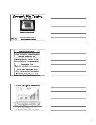
for several static load tests by utilizing dynamic testing also<br />
reduced cost and construction time.<br />
Once the Value Engineering Designs were approved,<br />
Loftus embarked on an aggressive schedule to allow the client<br />
to begin marketing the property and establishing closing<br />
dates for the condominiums. Multiple operations were<br />
occurring on this site to maintain the aggressive schedule,<br />
with dozers, excavators and pans weaving in and around<br />
cranes installing piles. Concrete crews were constructing<br />
pile caps the day after piles were installed. After completion<br />
of the sheeting and bearing pile installation, Loftus still<br />
had to construct 300 support columns on the pile caps and<br />
150,000 sf of a 13-inch thick, post-tensioned podium slab<br />
over the parking level to support the building structure. An<br />
alternate post-tensioning scheme was developed by Loftus to<br />
further reduce construction time and<br />
to assure concurrent work throughout<br />
the site.<br />
Upon completion of the contract<br />
work, Loftus was called back to the site<br />
to solve two additional problems. The<br />
first issue was that of an area subject<br />
to scour during flood events located<br />
between the retention basin and the<br />
adjacent creek. The resolution was<br />
to construct a permanent spillway at<br />
this location utilizing 138 LF of steel<br />
sheet piles. This solution also served<br />
to increase flow capacity into and out<br />
of the retention basin for future flood<br />
events. An excavator with a vibratory<br />
hammer was used to install these<br />
sheets. Access to the site was minimal<br />
at this point in the land development<br />
process and the only access to this<br />
location was via berm along the edge<br />
of the retention basin. The 70- and<br />
Project Spotlight<br />
80-ton sized crawler cranes used to install sheets and piles<br />
earlier in the project were too large to traverse this berm.<br />
By utilizing the excavator, access was no longer an issue and<br />
additional restoration was minimized.<br />
The client then wished to add a swimming pool within<br />
the limits of the parking area and under the recently constructed<br />
podium slab in an area with only 10 feet of vertical clearance.<br />
To make matters worse, the location of the proposed pool<br />
interfered with the recently installed tie rods. This presented a<br />
challenge because the sheet pile retaining wall system relied on<br />
the dead weight of the soil above the deadmen and tiebacks.<br />
The installation had to be sequenced such that the integrity<br />
of this system was continuously maintained. A new deadman<br />
was constructed roughly 15 feet behind the original deadman<br />
and was anchored to the original deadman with thru-anchors.<br />
A concrete protection slab with a backup drainage system was<br />
also constructed beneath the pool itself to channel water away<br />
from the tie rods in the event of a future leak. This solution<br />
was also designed by Loftus. Had the original deep foundation<br />
system of concrete T-walls and auger cast piles been instituted,<br />
it would never have been possible to install this pool. Because<br />
of the revised systems chosen, the client was able to achieve an<br />
18-foot by 40-foot lap pool up to 6 feet deep.<br />
• Q4 • 2008<br />
53