Cisco 1262 Wireless Access Point Installation Manual - Interlogix
Cisco 1262 Wireless Access Point Installation Manual - Interlogix
Cisco 1262 Wireless Access Point Installation Manual - Interlogix

Create successful ePaper yourself
Turn your PDF publications into a flip-book with our unique Google optimized e-Paper software.
<strong>Cisco</strong> <strong>1262</strong> <strong>Wireless</strong> <strong>Access</strong> <strong>Point</strong><br />
<strong>Installation</strong> <strong>Manual</strong><br />
Content<br />
Introduction 1<br />
<strong>Installation</strong> 1<br />
Installing a padlock (optional) 3<br />
Connecting the MobileView antenna 3<br />
Confirm access point power 4<br />
FCC compliance 4<br />
Contact information 4<br />
Mounting bracket template 5<br />
Introduction<br />
The <strong>Cisco</strong> ® Aironet ® <strong>1262</strong> <strong>Wireless</strong> <strong>Access</strong> <strong>Point</strong> is<br />
made for interior use only.<br />
Mount the access point in a secure location (inside<br />
the vehicle in a secure cabinet if possible).<br />
Ensure that the access point is in a well-ventilated<br />
area.<br />
Read through these instructions before installation.<br />
Note: A qualified service person, complying with all<br />
applicable codes, should perform all required<br />
hardware installation.<br />
To use this document, you must have the following<br />
minimum qualifications:<br />
A basic knowledge of electrical wiring and lowvoltage<br />
electrical hookups.<br />
<strong>Installation</strong><br />
Before beginning, confirm you have all contents<br />
required:<br />
<strong>Cisco</strong> ® Aironet ® <strong>1262</strong> <strong>Wireless</strong> <strong>Access</strong> <strong>Point</strong><br />
Mounting bracket (included with the access point)<br />
<strong>Cisco</strong> ® Aironet ® <strong>1262</strong> PoE Power Supply Unit<br />
MobileView <strong>Wireless</strong> Antenna<br />
Two Cat 5 Ethernet cables<br />
Required screws and washers for mounting the access<br />
point and power supply (not included). Mounting<br />
hardware is included with the antenna.<br />
Part Numbers:<br />
MSS-MISC-WIFI-126N:<br />
MSS-MISC-WIFI-PS:<br />
<strong>Cisco</strong> ® Aironet ® <strong>1262</strong> <strong>Wireless</strong><br />
<strong>Access</strong> <strong>Point</strong><br />
<strong>Cisco</strong> ® Aironet ® <strong>1262</strong> <strong>Wireless</strong><br />
<strong>Access</strong> <strong>Point</strong> Power Supply<br />
MSS-MISC WIFIPS-CAB: Power Supply Cable<br />
MSS-MISC-ANT-4-240:<br />
MSS-MISC-ANT-3-240:<br />
Mounting the <strong>Access</strong> <strong>Point</strong><br />
Quad-band antenna (supports<br />
PENTA GPS)<br />
802.11 antenna for installations<br />
with a MV-3000 DVR<br />
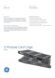
A mounting bracket (see Figure 1) is included with the<br />
access point. The mounting bracket comes detached<br />
from the access point. The four protruded holes in the<br />
mounting bracket are used to attach the bracket to the<br />
mounting surface.<br />
Note: No hardware is required to attach the access<br />
point to the mounting bracket.<br />
<strong>Cisco</strong> <strong>1262</strong> <strong>Access</strong> <strong>Point</strong> <strong>Installation</strong> <strong>Manual</strong> 1
1. Examine the access point to see how it attaches to<br />
the mounting bracket and to ensure that the chosen<br />
mounting location allows clearance for the network<br />
cable connection.<br />
Figure 1. Low-profile Mounting Bracket Installed on an access point<br />
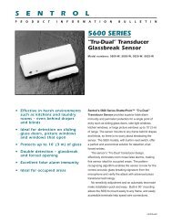
NOTE: If the vehicle does not have an existing wire<br />
harness equipped with a mating Mate-N-Lok connector<br />
specifically to power a MobileView wireless radio at<br />
12VDC, the connector can be removed to connect the<br />
V+ and V- wire leads to the DVRs wiring harness (refer<br />
to the DVR wiring pin-out diagram).<br />
Figure 2. Connect the power cable<br />
2. Using the mounting bracket as a guide, mark the<br />
position of the four mounting holes on the mounting<br />
surface. If the network cable to the access point will<br />
be routed through the mounting surface, cut a hole<br />
large enough for an Ethernet cable positioned under<br />
the cable bay area of the access point.<br />
3. Drill the 4 mounting holes with an appropriate bit for<br />
the metal or fiberglass vehicle surface.<br />
4. Install stainless steel rivnuts in any holes through<br />
fiberglass. Stainless steel self-tapping screw may<br />
be used in any holes through metal.<br />
5. If the network cable is routed through the mounting<br />
surface, pull about 8 in. of cable through prior to<br />
securing the bracket to the surface.<br />
6. Insert machine screws in the rivnut holes and selftapping<br />
metal screws in any holes that are drilled<br />
directly into metal.<br />
Install the Power Supply<br />
1. Position the Power Supply near the DVR.<br />
2. Secure the power supply to the rack or mounting<br />
surface by installing appropriate screws in the<br />
mounting holes.<br />
3. Connect the 48 in. power cable, UTC PN MSS-<br />
MISC-WIFI-PS-CAB, to the <strong>Access</strong> <strong>Point</strong> Power<br />
Supply as shown in Error! Reference source not<br />
ound. below. The green terminal block snaps into<br />
the power supply as shown. The opposite end of<br />
the power supply cable with the Mate-N-Lok plug<br />
connects to the vehicle wiring harness.<br />
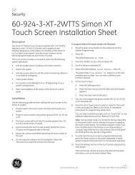
Connect the Network Cables<br />
The access point has one port labeled CONSOLE and<br />
one labeled ETHERNET. The power supply has one port<br />
labeled IN and one labeled OUT.<br />
1. Connect the network cable to the access point port<br />
labeled ETHERNET.<br />
2. Connect the other end of that same network cable to<br />
the access point port labeled OUT.<br />
3. Connect a network cable from the DVRs GIGIBIT<br />
NET port to the IN port on the power supply.<br />
4. Ensure that the network is wired correctly as shown<br />
in Figure 3.<br />
Figure 3. Network cable connection<br />
5. Attach the access point to the mounting bracket,<br />
tucking the cable into the cable bay area.<br />
2 <strong>Cisco</strong> <strong>1262</strong> <strong>Access</strong> <strong>Point</strong> <strong>Installation</strong> <strong>Manual</strong>
Installing a padlock (optional)<br />
Use the security hasp on the adapter cable access<br />
cover and a padlock (that you provide) to secure your<br />
access point to the mounting plate. Compatible<br />
padlocks are Master Lock models 120T or 121T. The<br />
cable access cover on the mounting bracket covers the<br />
cable bay area (including the power port, Ethernet port,<br />
console port, and mode button) to prevent access.<br />
Connecting the MobileView antenna<br />
The <strong>Cisco</strong> <strong>1262</strong> <strong>Access</strong> <strong>Point</strong> has six antenna ports:<br />
three labeled 2.4 GHz ANTENNA as shown in Figure 6<br />
below; and three labeled 5 GHz ANTENNA as shown in<br />
Error! Reference source not found. below.<br />
Figure 6. Three antenna ports labeled 2.4 GHz ANTENNA<br />
Follow these instructions to install the padlock:<br />
1. With the access point installed on the mounting<br />
bracket, insert a padlock into the security hasp.<br />
Note: If your access point is mounted to a hard<br />
ceiling, the clearance between the mounting bracket<br />
and the ceiling is small. Work slowly using both hands<br />
to position and secure the lock into the mounting<br />
bracket hasp.<br />
Figure 7. Three antenna ports labeled 5 GHz ANTENNA<br />
2. Rotate the lock clockwise and align the bail with the<br />
lock body.<br />
3. Grasp the lock and push it into the bail to lock the<br />
lock. See Figure 4.<br />
Figure 4. Inserting the padlock into the security hasp<br />
Each port has a black rubber protective cap, as shown in<br />
Figure 8 below.<br />
Figure 8. Black protective caps shown on four ports<br />
4. Rotate the padlock into the padlock area. See<br />
Figure 5.<br />
Figure 5. Rotating the padlock into the padlock area<br />
Unless instructed otherwise for your specific installation,<br />
remove the three protective rubber caps from the access<br />
point ports labeled 5 GHz ANTENNA.<br />
1. Attach the three 802.11 antenna cables to the three<br />
5 GHz access point ANTENNA ports.<br />
2. If the wireless antenna is part number MSS-MISC-<br />
ANT-4-240 and the DVR is a MobileView PENTA,<br />
connect the fourth antenna cable to the DVRs GPS<br />
port.<br />
<strong>Cisco</strong> <strong>1262</strong> <strong>Access</strong> <strong>Point</strong> <strong>Installation</strong> <strong>Manual</strong> 3
Confirm access point power<br />
There is a small LED on the face of the access point,<br />
shown in Figure 8 as the small black square above the<br />
CISCO label.<br />
When the access point is receiving power, the LED<br />
should illuminate green. The LED may flash initially and<br />
then become solid green. This confirms the access<br />
point is powered on.<br />
FCC compliance<br />
This equipment has been tested and found to comply<br />
with the limits for a Class B digital device, pursuant to<br />
part 15 of the FCC Rules. These limits are designed to<br />
provide reasonable protection against harmful<br />
interference when the equipment is operated in a<br />
commercial environment. This equipment generates,<br />
uses, and can radiate access point frequency energy<br />
and, if not installed and used in accordance with the<br />
installation instructions, may cause harmful interference<br />
to access point communications.<br />
You are cautioned that any changes or modifications<br />
not expressly approved by the party responsible for<br />
compliance could void the user’s authority to operate<br />
the equipment.<br />
Contact information<br />
North America:<br />
855-MOBVIEW (662-8839)<br />
MobileViewTS@fs.utc.com<br />
Latin America:<br />
561-998-6114<br />
latam@interlogix.com<br />
Web site:<br />
www.interlogix.com/mobileview<br />
4 <strong>Cisco</strong> <strong>1262</strong> <strong>Access</strong> <strong>Point</strong> <strong>Installation</strong> <strong>Manual</strong>
Mounting bracket template<br />
Use the mounting bracket template to mark the positions of the mounting and cable entry holes on the mounting<br />
surface.<br />
2013003 March 2013<br />
© 2013 <strong>Interlogix</strong>, Inc.<br />
<strong>Cisco</strong> is the trademark of <strong>Cisco</strong> Systems, Inc. and/or its affiliates in the U.S. and other countries.<br />
www.interlogix.com/mobileview