ThermaSol PowerPak Series Installation ... - Sauna Supplies
ThermaSol PowerPak Series Installation ... - Sauna Supplies
ThermaSol PowerPak Series Installation ... - Sauna Supplies

You also want an ePaper? Increase the reach of your titles
YUMPU automatically turns print PDFs into web optimized ePapers that Google loves.
<strong>ThermaSol</strong> <strong>PowerPak</strong> <strong>Series</strong><br />
<strong>Installation</strong> & Operating Instructions<br />
Commercial Steam Bath Generators (Three Phase)<br />
CUSTOMER WARNINGS<br />
• DO NOT USE THIS PRODUCT UNLESS YOU HAVE CONSULTED YOUR DOCTOR AND RECEIVED WRITTEN<br />
PERMISSION TO DO SO. USE OF THIS PRODUCT MAY BE HAZARDOUS TO YOUR HEALTH.<br />
• STEAM IS HOT! DO NOT TOUCH OR GO NEAR THE STEAM HEAD FROM THE TIME THE UNIT IS “ON”, UP TO<br />
ONE HOUR FROM THE TIME THE UNIT IS OFF. SEVERE BURN WILL OCCUR IF YOU COME IN CONTACT WITH<br />
THE STEAM HEAD OR STEAM EMITTING FROM THE STEAM HEAD.<br />
• NEVER ATTEMPT TO FILL AROMA THERAPY RESERVOIR ON THE STEAM HEAD WHEN UNIT IS IN THE “ON”<br />
POSITION. SEVERE BURNS WILL OCCUR.<br />
• DO NOT USE THERMASOL AROMA THERAPY OILS OR SKIN CARE PRODUCTS OR ANY PRODUCT IN<br />
CONJUNCTION WITH YOUR THERMASOL UNIT WITHOUT CONSULTING WITH YOUR ALLERGIST OR DOCTOR<br />
BEFORE USE. THESE PRODUCTS MAY BE HAZARDOUS TO YOUR HEALTH.<br />
• YOUR SHOWER MAY BE A SLIP AND FALL HAZARD CHECK WITH YOUR CONTRACTOR OR TILE<br />
MANUFACTURER REGARDING THE SAFE USE OF YOUR FLOORING IN A STEAM APPLICATION. SLIPPING<br />
AND FALLING INTO THE STEAM HEAD ITSELF OR INTO THE STREAM OF STEAM EMITTING FROM THE<br />
STEAM HEAD WILL CAUSE SERIOUS BURNS, OR PHYSICAL INJURY.<br />
• DO NOT USE A STEAM ROOM WHILE UNDER THE INFLUENCE OF ALCOHOL OR DRUGS, AS THIS CAN BE<br />
HAZARDOUS TO YOUR HEALTH.<br />
• IF YOU ARE FEELING UNCOMFORTABLE, DIZZY, FAINT, OR STARTING TO FALL ASLEEP, IMMEDIATELY EXIT<br />
THE STEAM ROOM.<br />
• DO NOT USE A STEAM ROOM IF YOU ARE UNDER THE AGE OF 16 UNLESS SUPERVISED BY AN ADULT.<br />
• THERMASOL GENERATORS ARE FOR INDOOR USE ONLY. THEY SHOULD NEVER BE LOCATED OUTSIDE<br />
THE HOME.<br />
• THERMASOL GENERATORS ARE NOT TO BE USED FOR SPACE HEATING PURPOSES.<br />
• FOR SAFETY, SMOOTH OPERATION PRACTICE AND LIABILITY. IF YOU ARE A PLUMBER/INSTALLER,<br />
PLEASE ENSURE THIS OWNERS MANUAL & WARRANTY INFORMATION IS IN THE OWNER’S POSSESSION<br />
WITH SPECIFIC DELEGATION FOR THE PURPOSE OF COMPLETELY FAMILIARIZING ANY USERS WITH THIS<br />
PRODUCT.<br />
• FAILURE TO FOLLOW INSTALLATION INSTRUCTIONS SPECIFICALLY WILL CAUSE THE WARRANTY TO BE<br />
VOID.<br />
Note: For better technical assistance and before contacting Technical Support, please have this<br />
model number, serial number, and date code ready.<br />
PLACE SERIAL # HERE<br />
TECHNICAL AND WARRANTY SUPPORT ONLY: 1-800-776-0711<br />
(Monday – Thursday, 7:00 a.m. to 5:00 p.m. PST; Friday, 8:00 a.m. – 12:00 p.m. PST)<br />
FOR ALL OTHER CUSTOMER SUPPORT PLEASE CONTACT YOUR DEALER<br />
DATE<br />
CODE<br />
HERE<br />
Doc. No: 81128 Page 1 of 16 Revision A 01/08/08 SAS
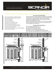
Sizing Your Steam Room<br />
Steam Room Size Formula: L X W X H = volume in cubic feet (ft 3 )<br />
All measurements to be in units of feet. For non-standard ceilings (above 8 ft. high), apply a<br />
correction factor (add 10% per foot).<br />
Examples:<br />
a 9 ft. ceiling requires correction factor 1.1 x (room size)<br />
a 10 ft ceiling requires correction factor 1.2 x (room size)<br />
Model Number Steam Room Capacity<br />
(cu. ft.)<br />
PP-450-240 450<br />
PP-600-240 600<br />
PP-800-240 800<br />
PP-450-480 450<br />
PP-600-480 600<br />
PP-800-480 800<br />
For further assistance call toll-free 800-776-0711<br />
Doc. No: 81128 Page 2 of 16 Revision A 01/08/08 SAS
Generator <strong>Installation</strong> Instructions<br />
Parts Enclosed<br />
• Steam generator / built-in control<br />
• Steam room sensor & 25 foot<br />
lead wire<br />
• Polished chrome steam head<br />
• 60 Minute Mechanical Timer<br />
Materials Needed<br />
• Brass ball valve<br />
• Pipe compound<br />
• Copper or brass nipples<br />
(Size and quantities per<br />
Instructions)<br />
• In-line filter (recommended)<br />
• 3/8” brass or copper union<br />
• Wire (sizes and quantities per<br />
Instructions)<br />
• Copper tubing or pipe<br />
• Wire cap nuts<br />
• Flex conduit<br />
• Brass or copper tee<br />
fitting & plug<br />
Tools Needed<br />
• Pipe wrench<br />
• Tubing cutter<br />
• Flaring tool (if flared fittings<br />
are used)<br />
• Pipe thread cap<br />
• Wire cutters or wire strippers<br />
• Adjustable wrench<br />
• Screwdrivers ( Philips &<br />
slotted)<br />
• Solder & flux<br />
• 3/16” & 1.5” masonry drill bits<br />
• Drill motor<br />
• Propane torch<br />
• Other tools as required<br />
Figure 1: Generator Dimensions<br />
All <strong>ThermaSol</strong> steam generators are designed<br />
to build NO PRESSURE during operation. This<br />
is for your safety.<br />
NOTE: Failure to follow instructions<br />
specifically will cause warranty to be void.<br />
Doc. No: 81128 Page 3 of 16 Revision A 01/08/08 SAS
<strong>Installation</strong> Requirements<br />
1. Use copper or brass fittings only. NEVER USE GALVANIZED FITTINGS!<br />
2. The water inlet, steam outlet, and pressure relief valve, require brass unions.<br />
3. The generator must be upright, accessible and on a level surface with all connections on<br />
the back. The Access Panel (top and front of unit), as well as rear of the unit must be<br />
unobstructed and allow for easy access.<br />
4. Unit may be installed up to 50 feet away from shower area.<br />
5. Do not plumb a trap in the steam line or plumb the pressure relief valve into the steam line.<br />
6. Pitch steam line back towards generator avoid perfectly level plumbed lines.<br />
7. Before connecting water line to the generator, flush water line into a five-gallon pail to remove<br />
any silt or other materials that may be in the line. A <strong>ThermaSol</strong> in-line water filter is<br />
recommended.<br />
Caution:<br />
If the unit is run without water, serious damage may<br />
result! This possible damage is not covered under<br />
<strong>ThermaSol</strong>’s limited warranty.<br />
Note: Failure to follow specific installation instructions will cause the warranty to be void.<br />
Water Inlet<br />
Refer to Figure 2A for the following:<br />
1. Connect tee to the hot or cold water line. Install copper pipe or tubing to the tee. If an in-line<br />
filter is to be installed on the water line to the generator, (which is suggested), it would be<br />
preferable to install the tee on the cold water line.<br />
2. Install a brass shut-off valve on the water inlet line in an accessible area prior to the brass<br />
union and recommended in-line water filter.<br />
3. Before making the last connection to the 3/8” water inlet line coming to the unit, flush the<br />
water line into a five-gallon pail to remove any silt or other materials that may be in the line.<br />
4. Make the final connection and turn on water. All <strong>ThermaSol</strong> generators are equipped with an<br />
automatic water fill system. The water will stop after unit is filled.<br />
IMPORTANT: MAXIMUM WATER PRESSURE IS 70 P.S.I.<br />
Doc. No: 81128 Page 4 of 16 Revision A 01/08/08 SAS
Parts Enclosed<br />
• Deluxe steam head<br />
• Escutcheon<br />
Tools Needed<br />
• Pipe wrench<br />
• 1.5” cutting tool<br />
• Silicone gun<br />
• Other tools as required<br />
STEAM HEAD INSTALLATION<br />
IMPORTANT NOTE!<br />
LOCATE THE STEAM HEAD 6” INCHES BELOW CEILING AND 6 INCHES FROM NON<br />
BENCHED/SEATED/DOOR INTERIOR WALL CORNER. STEAM HEAD IS TO BE<br />
MOUNTED AS FAR AS POSSIBLE FROM TYPICAL BATHING POSITION (SEATED OR<br />
STANDING) AND AS FAR FROM CONTROL AS POSSIBLE WHILE MAINTAINING<br />
APPROXIMATELY A – 60” CONTROL HEIGHT.<br />
1. Drill a 1 1/2” diameter hole in the shower wall or wall above the bathtub for the steam outlet line.<br />
2. Connect 1” copper pipe or copper tubing onto the steam outlet with a 1” union. Run a 1” copper pipe<br />
from the union to the 1 1/2” hole in wall.<br />
3. Attach the steam head and escutcheon to the copper pipe. CAUTION: Do not obstruct the steam<br />
line with any shut-off valves, plugs or caps. All Steam Suite generators are designed to build NO<br />
PRESSURE.<br />
4. The steam line can run up, down, or horizontal; but cannot run down and then up. If it does, a steam<br />
trap will be produced at the low point blocking the flow of steam. Insulate the steam outlet piping if<br />
the piping run exceeds 10 feet or is exposed to cold areas. NOTE: Use steam rated insulation (225<br />
°F minimum).<br />
WARNING: Avoid contact with steam head! It will burn you. Avoid direct contact with the<br />
steam coming out of the steam head! It is extremely hot! It will burn you!<br />
NOTE: DO NOT mount sensor near steamhead!<br />
1” copper pipe<br />
Doc. No: 81128 Page 5 of 16 Revision A 01/08/08 SAS
See Page 5<br />
Doc. No: 81128 Page 6 of 16 Revision A 01/08/08 SAS
CONSUMER WARNING<br />
WARNING<br />
DO NOT USE THIS PRODUCT UNLESS YOU HAVE CONSULTED WITH YOUR DOCTOR AND RECEIVED<br />
WRITTEN PERMISSION TO DO SO. USE OF THIS PRODUCT MAY BE HAZARDOUS TO YOUR HEALTH.<br />
WARNING<br />
NEVER ATTEMPT TO FILL AROMA RESERVOIR ON THE STEAM HEAD WHEN UNIT IS IN<br />
THE ON POSITION. SEVERE BURNS MAY OCCUR.<br />
WARNING<br />
DO NOT USE AROMA THERAPY OILS OR SKIN CARE PRODUCTS OR ANY PRODUCT IN<br />
CONJUNCTION WITH YOUR UNIT WITHOUT CONSULTING WITH YOUR ALLERGIST OR DOCTOR<br />
BEFORE USE. THESE PRODUCTS MAY BE HAZARDOUS TO YOUR HEALTH.<br />
WARNING<br />
YOUR SHOWER MAY BE A SLIP AND FALL HAZARD CHECK WITH YOUR CONTRACTOR OR<br />
FLOORING MANUFACTURER REGARDING THE SAFE USE OF YOUR FLOORING IN A STEAM<br />
APPLICATION. SLIPPING AND FALLING INTO THE STEAM HEAD ITSELF OR INTO THE STREAM OF<br />
STEAM EMITTING FROM THE STEAM HEAD WILL CAUSE SERIOUS BURNS, OR PHYSICAL INJURY.<br />
WARNING<br />
STEAM IS HOT! DO NOT TOUCH OR GO NEAR THE STEAM HEAD FROM THE TIME THE UNIT IS<br />
“ON”, UP TO ONE HOUR AFTER IT HAS SHUT OFF. SEVERE BURN WILL OCCUR IF YOU COME IN<br />
CONTACT WITH THE STEAM HEAD OR STEAM EMITTING FROM THE STEAM HEAD.<br />
WARNING<br />
DO NOT USE STEAM ROOM WHILE UNDER THE INFLUENCE OF ALCOHOL OR DRUGS, AS THIS<br />
CAN BE HAZARDOUS TO YOUR HEALTH.<br />
WARNING<br />
IF YOUR ARE FEELING UNCOMFORTABLE, DIZZY, FAINT, OR STARTING TO FALL ASLEEP<br />
IMMEDIATELY EXIT THE STEAM ROOM.<br />
WARNING<br />
DO NOT USE STEAM ROOM IF YOU ARE UNDER THE AGE OF 16 UNLESS SUPERVISED BY AN<br />
ADULT.<br />
Doc. No: 81128 Page 7 of 16 Revision A 01/08/08 SAS
Electrical <strong>Installation</strong><br />
Note: All electrical wiring must be done per local electrical codes<br />
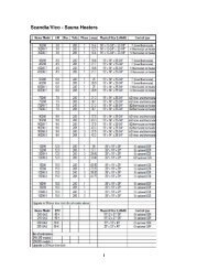
Wire sizes recommended by National Electric Code. Minimum wire temperature rating 90 °C.<br />
Generator Voltage Phase Wire Load Breaker Fuse Cubic kW<br />
Model<br />
Gauge Amps Size<br />
Feet<br />
PP-450-240 8 35A 40A 30A 450 13.5<br />
PP-600-240 240V<br />
6 47A 60A 40A 600 18<br />
PP-800-240<br />
4 63A 70A 45A 800 24<br />
3<br />
PP-450-480 10 16A 25A 15A 450 13.5<br />
PP-600-480 480V<br />
8 22A 30A 20A 600 18<br />
PP-800-480<br />
8 29A 40A 25A 800 24<br />
1. Turn off all electricity to the working area at the main breaker panel.<br />
2. Connect 240 or 480 VAC (model dependant) electrical lines to terminals labeled L1,<br />
L2, and L3 on the contactor (Figure 3). The system uses 4 wire (3 phase and<br />
ground). See wiring diagrams (Figure 4).<br />
3. Install the temperature control sensor with bulb guard in the steam room 4 to 6 feet<br />
above the floor (Figure 2A).<br />
NOTE: DO NOT mount sensor near steam head!<br />
4. Bring the control sensor wire to the generator. With the top cover removed (Figure 3)<br />
connect the control sensor wires, using ¼” push-on connectors to the control panel<br />
labeled “TEMP SENSOR”.<br />
5. Connect Control Timer to the “TIMER” connection on the control panel using two ¼”<br />
push-on connectors.<br />
6. Replace top access cover. Turn on both water and power to the generator!<br />
Instructions continue in page 10.<br />
7. Test the touch pad to ensure it is properly wired. If any technical problems arise, call<br />
toll-free 800-776-0711.<br />
Failure to follow installation instructions specifically may cause the warranty to be void!<br />
Doc. No: 81128 Page 8 of 16 Revision A 01/08/08 SAS
TEMP SENSOR<br />
MECH TIMER<br />
Figure 3A: 240V Wiring Diagram<br />
Figure 3B: 480V Wiring Diagram<br />
Doc. No: 81128 Page 9 of 16 Revision A 01/08/08 SAS
CONSUMER WARNING<br />
WARNING<br />
DO NOT USE THIS PRODUCT UNLESS YOU HAVE CONSULTED WITH YOUR DOCTOR AND RECEIVED<br />
WRITTEN PERMISSION TO DO SO. USE OF THIS PRODUCT MAY BE HAZARDOUS TO YOUR HEALTH.<br />
WARNING<br />
NEVER ATTEMPT TO FILL AROMA RESERVOIR ON THE STEAM HEAD WHEN UNIT IS IN<br />
THE ON POSITION. SEVERE BURNS MAY OCCUR.<br />
WARNING<br />
DO NOT USE AROMA THERAPY OILS OR SKIN CARE PRODUCTS OR ANY PRODUCT IN<br />
CONJUNCTION WITH YOUR UNIT WITHOUT CONSULTING WITH YOUR ALLERGIST OR DOCTOR<br />
BEFORE USE. THESE PRODUCTS MAY BE HAZARDOUS TO YOUR HEALTH.<br />
WARNING<br />
YOUR SHOWER MAY BE A SLIP AND FALL HAZARD CHECK WITH YOUR CONTRACTOR OR<br />
FLOORING MANUFACTURER REGARDING THE SAFE USE OF YOUR FLOORING IN A STEAM<br />
APPLICATION. SLIPPING AND FALLING INTO THE STEAM HEAD ITSELF OR INTO THE STREAM OF<br />
STEAM EMITTING FROM THE STEAM HEAD WILL CAUSE SERIOUS BURNS, OR PHYSICAL INJURY.<br />
WARNING<br />
STEAM IS HOT! DO NOT TOUCH OR GO NEAR THE STEAM HEAD FROM THE TIME THE UNIT IS<br />
“ON”, UP TO ONE HOUR AFTER IT HAS SHUT OFF. SEVERE BURN WILL OCCUR IF YOU COME IN<br />
CONTACT WITH THE STEAM HEAD OR STEAM EMITTING FROM THE STEAM HEAD.<br />
WARNING<br />
DO NOT USE STEAM ROOM WHILE UNDER THE INFLUENCE OF ALCOHOL OR DRUGS, AS THIS<br />
CAN BE HAZARDOUS TO YOUR HEALTH.<br />
WARNING<br />
IF YOUR ARE FEELING UNCOMFORTABLE, DIZZY, FAINT, OR STARTING TO FALL ASLEEP<br />
IMMEDIATELY EXIT THE STEAM ROOM.<br />
WARNING<br />
DO NOT USE STEAM ROOM IF YOU ARE UNDER THE AGE OF 16 UNLESS SUPERVISED BY AN<br />
ADULT.<br />
Doc. No: 81128 Page 10 of 16 Revision A 01/08/08 SAS
<strong>ThermaSol</strong> <strong>PowerPak</strong> <strong>Series</strong><br />
Control Operating Instructions<br />
1. Ensure electrical/plumbing installation is complete (see page 7,<br />
note 6) – turn on power to unit at the breaker. You will see a<br />
message SET CLOC that means a valid time has to be set prior<br />
to any operation. To proceed, press DAY button once. The<br />
display will change to 00:00 and the day will blink Sunday. Wait 5<br />
seconds. After 5 seconds, the system will accept this as the valid<br />
time. To set the correct time, use the UP or DOWN to adjust the<br />
time. Press DAY until you reach the correct day of week. Wait 5<br />
seconds. After 5 second, the display will now show the time and<br />
day of the week. The time displayed is a 24-hour clock while the<br />
day of week of marked by an led next to the DAY label.<br />
2. Now you will set the “Steam Start Time”. Press the SET button<br />
once. You should see the light next to the “Start Time” come on<br />
and red light next to ALL day. The ALL feature sets the start time<br />
for all 7 days. This saves time on entering redundant information<br />
7 times. Using the DAY button, you can individually change the<br />
start time of a specific day. The system comes from the factory<br />
with default values of 7:00 start time for all seven days. Using the<br />
arrows set the time you want the steam to begin on that day from<br />
now onward.<br />
3. Next, set the “Steam Stop Time” using similar way as the Start<br />
Time. Press the SET button once. You should see the light next<br />
to the “Stop Time”. Using the arrows set the time you want the<br />
steam to stop for that day from now onward. Note that you are<br />
either programming a specific day or ALL (1 week). If ALL was<br />
the day configured, the settings will be applied to all 7 days. If<br />
there is a need to modify specific days, press DAY to move to the<br />
desired day to modify the time.<br />
4. Pressing the SET button will let you see the current steam room<br />
temperature, and also enable you to configure the Temperature<br />
Set Point. Upon a first press of UP or DOWN, the set point will be<br />
displayed. Using the arrows set the temperature you want to be<br />
stored as the Set Point. This Generator will use this temperature<br />
as a threshold for turning on and off while keeping the steam<br />
room at constant desired temperature. This temperature is<br />
applied to all 7 days a week. After programming, to have the unit<br />
steam immediately, press the MANUAL button once.<br />
Doc. No: 81128 Page 11 of 16 Revision A 01/08/08 SAS
5. Pressing the SET button once again will enable you to set the<br />
Power Clean System (Figure 4) start time. You should see the<br />
light next to the “Power Clean Time” come on and the display will<br />
show the Power Clean time for the configuration day. Using the<br />
arrows, set the time you want the flush to start for that day from<br />
now press the DAY button for each day and using the arrows to<br />
set the time you want the unit to begin its Power Clean cycle.<br />
Once again the use of ALL for the day will apply the setting to all<br />
7 days while pressing the DAY button will allow you to modify the<br />
time for any specific day. The Power Clean stops automatically at<br />
the end of its cycle. (Approximately 45 minutes). Power clean<br />
start time can occur before start time (00:00 midnight, with 07:00<br />
start) or after hours (20:00 stop time, and 23:00 power clean start).<br />
CAUTION:<br />
Be sure there is noone in<br />
the shower area during<br />
this cycle!<br />
Figure 4: Tank maintenance - power cleaning the tank.<br />
TECHNICAL AND WARRANTY SUPPORT ONLY: 1-800-776-0711<br />
(Monday – Thursday, 7:00 a.m. to 5:00 p.m. PST; Friday, 8:00 a.m. – 12:00 p.m. PST)<br />
FOR ALL OTHER CUSTOMER SUPPORT PLEASE CONTACT YOUR DEALER<br />
Doc. No: 81128 Page 12 of 16 Revision A 01/08/08 SAS
Controller Notes and Tips<br />
• The system will revert back to displaying the current time and day after 1 minute of no<br />
button activity. The SET button is used to select between various display sets.<br />
• The ALL day feature is extremely useful as it give an ability to quickly set start, stop, and<br />
power clean times for all days. Then on days such as weekend days, the user can modify<br />
only those days eliminating the need to enter redundant information.<br />
• The system is equipped with usage odometer embedded in a special diagnostics menu.<br />
Pressing and holding the SET button for 5 seconds, will show the current firmware<br />
version of the control, this feature is important for customer service support. After 2<br />
seconds, the display will show the total hours the generator was on (heater on) in 10-hour<br />
increments. This number would help service the unit more efficiently as it will provide<br />
usage/time information.<br />
• The start, stop, and power clean times are related to each other automatically. The<br />
system is shipped from the factory with default values of 7:00 start, 20:00 stop, and 23:00<br />
power clean for all 7 days. The user can always revert (reset) back to these original<br />
defaults by pressing and holding the UP and DOWN buttons simultaneously for 5<br />
seconds.<br />
• If the start time reaches the stop time, the system will automatically fix that by pushing<br />
the stop time forward. Similarly, if stop reached start, it will attempt to push start<br />
backwards if possible until reaching 00:00. If both times will reach 5 minutes of power<br />
clean, the system will try to jump over 50 minutes after power clean, if it is unsuccessful, I<br />
will remain in previous setting.<br />
• The system supports temperature in both Fahrenheit and Celsius with a default factory<br />
setting of Fahrenheit. To change the units to Celsius, press the set button until you reach<br />
Temperature menu, and then press and hold the DAY button for 5 seconds and release.<br />
The system will toggle between units every 5 seconds while DAY button is depressed.<br />
• The MANUAL button enables operation without timing constrains set by start, stop, and<br />
power clean cycle. Pressing MANUAL will be marked by Manual mode red LED, turn on<br />
the generator and cancel power clean cycle. Automatic On and Off event will not control<br />
the generator. To cancel this mode, press the MANUAL button once again; the red LED<br />
will light next to Auto.<br />
The PAUSE button will halt the generator from producing steam. Pause mode will be<br />
marked by a red LED next to PAUSE. To resume regular operation, Press once again on<br />
PAUSE.<br />
• The system is equipped with a self-diagnostics error messaging system. Upon a system<br />
malfunction, an error message will be displayed with the following code numbers:<br />
Err 0 - General Code Error<br />
Err 1 - Pause button stuck<br />
Err 2 - Up button stuck<br />
Err 3 - Down button stuck<br />
Err 4 - Set button stuck<br />
Err 5 - Float switch tripped for 10 seconds<br />
Err 6 - Max heat exceeded<br />
Err 7 - Day button stuck<br />
Err 8 - Manual button stuck<br />
Err 9 - Temperature sensor is disconnected<br />
or not functioning<br />
** AFTER PROGRAMMING** To have the unit steam immediately, press the<br />
MANUAL button once.<br />
Doc. No: 81128 Page 13 of 16 Revision A 01/08/08 SAS
CONTACTOR<br />
208/240V<br />
COIL<br />
3<br />
2<br />
T3<br />
T2<br />
L3<br />
L2<br />
LINE IN<br />
LINE IN<br />
208/240V<br />
3 PHASE<br />
1<br />
T1<br />
L1<br />
LINE IN<br />
MECH.<br />
TIMER<br />
FUSES<br />
TOUCH<br />
PAD<br />
PCB<br />
TEMPERATURE SENSOR<br />
3 2<br />
1<br />
2 3 1<br />
FLOAT<br />
SWITCH<br />
HEATER A<br />
HEATER B<br />
(ORN)<br />
SOLDERLESS<br />
CRIMP<br />
(ORN)<br />
J1<br />
J2<br />
J3<br />
J7<br />
J6<br />
POWER<br />
SUPPLY<br />
PCB J4<br />
208/240V<br />
J5<br />
(RED)<br />
(RED)<br />
HEATER C<br />
208/240V<br />
SOLENOID<br />
Figure 4A: System Wiring Diagram – 240VAC, 3-Phase<br />
CONTACTOR<br />
240V COIL<br />
3<br />
T3<br />
L3<br />
LINE IN<br />
2<br />
T2<br />
L2<br />
LINE IN<br />
480 VAC<br />
3 PHASE<br />
1<br />
T1<br />
L1<br />
LINE IN<br />
MECH.<br />
TIMER<br />
FUSES<br />
480V<br />
TOUCH<br />
PAD<br />
PCB<br />
TEMPERATURE SENSOR<br />
STEP-DOWN<br />
TRANSFORMER<br />
240V<br />
FLOAT<br />
SWITCH<br />
3 2<br />
1<br />
2 3 1<br />
SOLDERLESS<br />
CRIMP<br />
J1<br />
HEATER A<br />
WIRE CAP<br />
CRIMP<br />
J2<br />
J4<br />
HEATER B<br />
J3<br />
J5<br />
J7<br />
(J6)<br />
HEATER C<br />
240V<br />
Figure 4B: System Wiring Diagram – 480VAC, 3-Phase<br />
Doc. No: 81128 Page 14 of 16 Revision A 01/08/08 SAS
THIS PAGE INTENTIONALLY LEFT BLANK<br />
Doc. No: 81128 Page 15 of 16 Revision A 01/08/08 SAS
POWERPAK WARRANTY<br />
12-month warranty from date of purchase for <strong>PowerPak</strong> generators on all parts found to have a manufacturing defect and<br />
labor required to replace those parts.<br />
EXCLUSION<br />
I. This service warranty does not cover: parts or product damaged in shipment; manufacturing defects observable prior to installation; parts<br />
or product damaged during installation; malfunction of equipment due to improper installation or installation not according to manufacturer<br />
specifications and/or installation instructions; use of cleaning solution not supplied by, or specifically approved by THERMASOL (Please<br />
refer to THERMASOL operating instruction manual for further information); parts or product installed in a manner that does not permit<br />
proper access to service; calcification build-up due to water condition and/or improper maintenance; damages to plated parts and<br />
accessories due to chemical corrosion or reaction; cosmetic damage; normal periodic cleaning and care or damage caused by not<br />
following manufacturer’s cleaning instructions; repairs caused by accident; neglect, misuse, vandalism, fire, lightning, earthquake, or any<br />
other peril; unauthorized and/or improper and modification or damage to structure. The Customer at the current labor and material charges<br />
shall pay any repair or installation modification that is subject to the above exclusion in effect at the time.<br />
II.<br />
III.<br />
THERMASOL will exercise reasonable efforts in rendering service under this warranty, but shall not be liable for any damage arising out of<br />
delays. This warranty only covers the repair and/or replacement as specified by the warranty.<br />
This warranty gives you specific legal rights and you may also have other rights, which may vary from state to state. Determination of<br />
rights under this warranty is in accordance with the laws in the state of California. Any dispute under the warranty must be submitted and<br />
resolved by arbitration in California.<br />
IV. THERMASOL does not guarantee that a local service person will be available. Unit may have to be removed and reinstalled at owner’s<br />
expense. It is the responsibility of the buyer to file a claim with the carrier/carriers for any product that has shipping damage to or from<br />
THERMASOL. An RMA (Return Merchandise Authorization) must be obtained from the factory and used on any correspondence or<br />
packages sent to the factory. THERMASOL, 2255 Union Place, Simi Valley, CA 93065 800-776-0711<br />
TERMINATION<br />
This warranty will be terminated by THERMASOL for the following reasons: Improper installation or use; service to equipment by unauthorized<br />
personnel; installation that does not permit proper access for service; non-payment of repairs not covered under warranty; non-remittance of<br />
completed warranty card. Modification to unit not authorized by THERMASOL; use of non-THERMASOL repair parts.<br />
THERMASOL POWERPAK REGISTRATION CARD / COMMERCIAL UNIT<br />
NAME OF FACILITY: PHONE: ( )<br />
ADDRESS: CITY: STATE: ZIP:<br />
I first heard about THERMASOL (please check one:)<br />
EMAIL:<br />
in a magazine/newspaper ad at a consumer trade show at the dealer or outlet where I purchased generator<br />
Website Other<br />
SERIAL NO.:<br />
DATE OF PURCHASE:<br />
MODEL:<br />
DEALER/OUTLET:<br />
INSTALLER NAME: PHONE: ( )<br />
INSTALLER ADDRESS: CITY: STATE: ZIP:<br />
CUSTOMER SIGNATURE:<br />
DATE INSTALLED:<br />
The generator is working: Satisfactory Unsatisfactory Comments:<br />
_______________________________________________________________________________________________________________________________________________________<br />
DOC 87006 REV A 02/05<br />
Doc. No: 81128 Page 16 of 16 Revision A 01/08/08 SAS