Ultra Sauna Gas Heater - Scandia Manufacturing
Ultra Sauna Gas Heater - Scandia Manufacturing
Ultra Sauna Gas Heater - Scandia Manufacturing

Create successful ePaper yourself
Turn your PDF publications into a flip-book with our unique Google optimized e-Paper software.
<strong>Heater</strong> Model __________<br />
Serial #<br />
__________<br />
Installation<br />
Guide<br />
ULTRA-SAUNA HEATER<br />
Proudly made in USA since 1964<br />
<strong>Gas</strong> <strong>Heater</strong>s - 40,000-80,000 BTU<br />
Installation Instructions<br />
& User Manual<br />
PO Box 636 Eagle Idaho USA. 83616<br />
T: 877.467.2862 F: 208.286.0290 info@scandiamfg.com www.scandiamfg.com<br />
1
Installation Instructions Guidelines<br />
<br />
<br />
<br />
<br />
<br />
<br />
<br />
<br />
<br />
<br />
<br />
<br />
Heat must be installed by a certified professional<br />
<strong>Heater</strong> must be installed according to local codes<br />
Do not touch the heater<br />
Do not cover the heater<br />
Never hose down the sauna<br />
<strong>Sauna</strong> door must always open outward<br />
<strong>Sauna</strong> door can never include a lock<br />
Do not install more than one heater in a room<br />
Only use an aroma-stone when using fragrances<br />
Never leave children unattended<br />
<strong>Sauna</strong> bathing is not suitable for those with health<br />
problems.<br />
Consult a doctor before using<br />
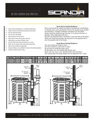
<strong>Sauna</strong> Room Venting Guidelines<br />
<strong>Sauna</strong> room should be vented according to manufacturers specifications<br />
or <strong>Scandia</strong> sauna room specification found in the <strong>Scandia</strong><br />
sauna installation instructions. Improper ventilation is dangerous<br />
for the health.<br />
<strong>Heater</strong> should be positioned near the door or on close to the door<br />
as possible without impeding traffic flow.<br />
The inlet vent should be below the heater or near the base of the<br />
heater.<br />
Outlet vent should be just below the top bench on the opposite<br />
side or near the opposite side of the heater.<br />
<strong>Sauna</strong> Room Venting Guidelines<br />
The sauna should not include a drain.<br />
The sauna should be constructed of cedar.<br />
Do not treat of varnish the sauna wood.<br />
Fill the heater only with <strong>Scandia</strong> high-density rocks<br />
Check rock tray once a year cleaning all dirt and rock pieces.<br />
The warning signs and usage plaque must be displayed near<br />
sauna.<br />
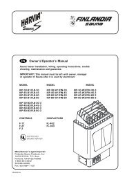
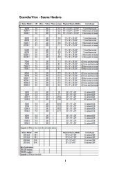
Models <strong>Heater</strong> Max Room Size A B C D E F G H I J K L N<br />
240 & 245 40,000 8' x 11' x 7' 28" 4" 18 1/2" 2 1/2" 20 x 32 8 1/4" x 13 1/4" 3 1/2" 24 1/2" 14" 7" 4" 10 1/4" 8"<br />
280 & 285 80,000 12' x 20' x 7' 40" 6" 29" 4" 33" x 45" 8 1/4" x 16 1/4" 5 1/2" 32" 20" 12" 6" 12 1/4" 14"<br />
I<br />
2
Installation Instructions guidelines<br />
Note: Your <strong>Scandia</strong> <strong>Ultra</strong> gas sauna heater should be installed only by a licensed electrician<br />
and HVAC professional. Improper and unofficial installation will void warranty.<br />
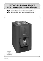
Roughing In<br />
1. Set galvanized back-up wall in place on face of<br />
studs. Centerline of the flue hole must be a<br />
minimum of 17 1/ 2 from side wall for 40,000<br />
BTU models and 26 1/2 for 80,000 BTU models.<br />
The metal tabs at the bottom are “spacers”<br />
and must rest on the finished floor. Nail to<br />
studs.<br />
2. The sides and top of galvanized back-up wall<br />
are used as plaster grounds. If materials other<br />
than cement plaster are used, fit material to<br />
edge of galvanized panel. If wall is to be more<br />
than 3/4” thick, spacers must be used between<br />
stud and back-up wall.<br />
3. Adjust vent and air intake collars on back-up<br />
wall to wall thickness. Each has plaster<br />
ground.<br />
4. The rough-in portion of control box should be<br />
nailed on stud facing outside the room and as<br />
far from the heater as possible.<br />
5. Place a nail 6” down from the ceiling on stud<br />
facing inside the sauna room. String a pull<br />
wire from the nail to the control box. Use this<br />
wire to bull thermo-bulb through the wall<br />
when the sauna room is finished. Do not bend<br />
the capillary tubing more than 90 deg at any<br />
point.<br />
6. Run the supplied low voltage wire from the<br />
control box to the heater burner assembly<br />
brining it through the air intake vent. An access<br />
hole has been provided on the vent. This<br />
is a three wire assembly, two are used one is a<br />
spare.<br />
7. Run the gas line with shut off valve into the air<br />
intake vent through the hole provided. Connect<br />
the gas line into the base of the gas<br />
valve.<br />
40,000 BTU 80,000 BTU<br />
A 18.5" 29"<br />
B 8" 12"<br />
C 7" 11"<br />
D 2 1/2" 4"<br />
Finish<br />
1. Place 1” fiberglass insulation into galvanized<br />
back-up wall.<br />
2. Remove paper from stainless flashing<br />
and start screws to galvanized (do not<br />
tighten)<br />
3. Slide heater into place, guide metal covered<br />
high-limit wires through the hole<br />
on the intake bracket. Secure heater to<br />
stainless steel flashing with two screws.<br />
4. Tighten screws on the corners of the<br />
flashing.<br />
5. Slip burner inside heater allowing the<br />
burner lip to fit under the burner<br />
bracket. Then bolt near end of burner to<br />
the intake channel.<br />
6. Place caution sign on flashing above<br />
heater.<br />
7. Hook up low voltage wires on gas valve<br />
(see attached illustration .<br />
8. Install flue cap (outside wall) : or draft<br />
hood (inside wall).<br />
9. Pull thermo-bulb through wall and attach<br />
six inches below ceiling as far away<br />
from heater as possible.<br />
10. Install heater guard rail.<br />
B<br />
A<br />
Cedar wall<br />
lining<br />
C<br />
0.515625" x 0.515625"<br />
D<br />
<strong>Gas</strong> Line<br />
0.41129032258065" x 0.41129032258065"<br />
0.20564516129032" x 0.20564516129032"<br />
3
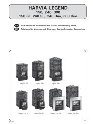
<strong>Gas</strong> Burner Overview - Standing Pilot<br />
Piezo Ignitor Overview<br />
4
60 Minute Control Wiring Overview<br />
24 Hour Control Wiring Overview<br />
5
Back Panel Assembly Rough-in for 40,000 BTU heaters<br />
To prepare or rough-in for your Am-Finn <strong>Ultra</strong>-<strong>Gas</strong> sauna heater, you must consider two area<br />
for rough-in. 1) the exhaust and air intake vents must be roughed-in through the wall extending<br />
to the outside. 2) the interior room cedar walls must be roughed-in to accommodate the<br />
back panel of the heater. NOTE: you must consult local code for all type B gas venting regulations<br />
and other gas appliance regulations before installing. Unit must be installed by a certified<br />
professional.<br />
20 1/4”<br />
Back Panel<br />
6 1/4”<br />
Through-wall rough-in.<br />
A) Exhaust vent (W 9 1/2 in x H 9 1/2<br />
in)<br />
B) Intake vent (W 13 3/4 in x H 6 in)<br />
(These measurements may vary due to difference in<br />
production runs).<br />
5 1/2”<br />
A<br />
Exhaust Vent<br />
9 1/2” x 9 1/2”<br />
5 1/2”<br />
32 1/4”<br />
8 1/4”<br />
20”<br />
1 1/2”<br />
B<br />
Air Intake Vent<br />
W 13 3/4 x H 6”<br />
5 1/4”<br />
3 ”<br />
3 1/2”<br />
floor<br />
Back Panel Rough-in - Back panel dimensions are<br />
W 20 1/2” x H 32 1/2”. When lining room with<br />
cedar, do not apply cedar to these specified back<br />
panel dimensions. This 20 1/4 and 32 1/4 in<br />
rough-in should be placed 3” from the floor.<br />
20 1/4”<br />
Cedar <strong>Sauna</strong> Wall<br />
Behind Cedar Wall Surface<br />
32 1/4”<br />
Through-wall rough-in<br />
(see above)<br />
6
Back Panel Assembly Rough-in for 80,000 BTU heaters<br />
To prepare or rough-in for your Am-Finn <strong>Ultra</strong>-<strong>Gas</strong> sauna heater, you must consider two area<br />
for rough-in. 1) the exhaust and air intake vents must be roughed-in through the wall extending<br />
to the outside. 2) the interior room cedar walls must be roughed-in to accommodate the<br />
back panel of the heater. NOTE: you must consult local code for all type B gas venting regulations<br />
and other gas appliance regulations before installing. Unit must be installed by a certified<br />
professional.<br />
31 1/2”<br />
Back Panel<br />
6 1/4”<br />
Through-wall rough-in.<br />
A) Exhaust vent (W in x H in)<br />
B) Intake vent (W in x H in)<br />
9-1/2”<br />
A<br />
Exhaust Vent<br />
9-1/2”<br />
44 “<br />
11-1/2”<br />
20-3/4”<br />
7”<br />
B<br />
Air Intake Vent<br />
W x H<br />
8-1/2”<br />
4-1/4 ”<br />
5”<br />
floor<br />
Back Panel Rough-in - Back panel dimensions are<br />
31-1/2” W x 44” H . When lining room with cedar,<br />
do not apply cedar to these specified back<br />
panel dimensions. This and in rough-in should<br />
be placed 4-1/4” from the floor.<br />
31-1/2”<br />
Cedar <strong>Sauna</strong> Wall<br />
Behind Cedar Wall Surface<br />
44”<br />
Through-wall rough-in<br />
(see above)<br />
7
<strong>Heater</strong> Component List<br />
1<br />
2<br />
3<br />
4<br />
5<br />
6<br />
7<br />
<strong>Heater</strong> Body Unit<br />
Back panel w/external through-wall covers<br />
Stainless steel flashing (internal back panel cover)<br />
Venting component option (flue cap or draft hood)<br />
Complete burner assembly (natural gas or propane)<br />
Control box with cover, wires, knobs<br />
Imported high-density sauna rocks<br />
1<br />
2<br />
or<br />
3<br />
4<br />
Flue Cap<br />
Draft Hood w/Elbow<br />
5<br />
6 7<br />
8