Air-Heated Vaporizers - Linde Engineering
Air-Heated Vaporizers - Linde Engineering
Air-Heated Vaporizers - Linde Engineering

Create successful ePaper yourself
Turn your PDF publications into a flip-book with our unique Google optimized e-Paper software.
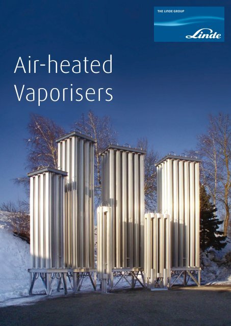
<strong>Air</strong>-heated<br />
Vaporisers
2<br />
Contents.<br />
3 Introduction<br />
4 General<br />
5 Lead-VAP and Special-VAP<br />
6 Lead-VAP<br />
Standard design<br />
8 Special-VAP<br />
HQ-standard design (for higher quality fluids)<br />
HD-standard design (for high pressure use)<br />
Clip-on standard design<br />
Pressure build-up standard design<br />
16 Operational efficiency<br />
Conversion factor<br />
Correction factor, power factor, sample calculations<br />
18 Know-how, quality, inspection, documentation<br />
22 SHEQ - safety, health, environment and quality police<br />
Subject to change without notice. Errors excepted.<br />
The reproduction, distribution and utilization of this<br />
prospectus as well as the communication of its contents<br />
to other with-out explicid authorization is prohibited.<br />
Offenders will be held liable for the payment of damages.<br />
All rights reserved in the event of the grant of a patent,<br />
utility model or design.<br />
23 Service and guarantee<br />
24 Contacts<br />
© <strong>Linde</strong> AG, April 2009
3<br />
Introduction.<br />
Carl von <strong>Linde</strong> - gifted engineer, scientist, entrepreneur,<br />
company´s founder and eponym of the <strong>Linde</strong> AG.<br />
With air liquefaction, Carl von <strong>Linde</strong> created the conditions needed<br />
to procedure pure gases using low-temperature processes. <strong>Air</strong> liquefaction<br />
was only the first step for Carl von <strong>Linde</strong> towards a commercial<br />
viable use for his invention. His goal was to separate the liquid<br />
air, while re-evaporating it, into its constituents, since only these<br />
held promising industrial potential.<br />
Carl von <strong>Linde</strong> created a new industry within just a few decades:<br />
refrigeration. His company was characterised from the very first<br />
beginning by innovativeness and close customer relations. This is<br />
what <strong>Linde</strong> stands for – in the past, today, and in face of future<br />
challenges, world-wide.<br />
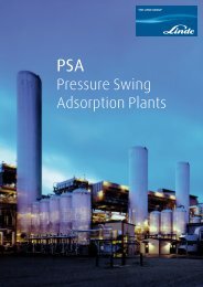
<strong>Linde</strong> as the world leader in adsorption technology has designed<br />
and supplied more than 400 PSA plants – including the world‘s<br />
largest units and units with highest availability.
4<br />
General.<br />
The recovery of large quantities of gases such<br />
as oxygen, nitrogen and argon is carried out<br />
through cryogenic decomposition of air. In the<br />
cryogenic (very cold) then condensed (liquid)<br />
states, these gases only take up around 1/800<br />
of the volume they would require in the gaseous<br />
state which is the reason why storage for<br />
consumers is carried out as a fluid in thermallyinsulated<br />
tanks at temperatures down to minus<br />
269°C. If required, the liquid gas is vaporised in<br />
a downstream vaporiser.<br />
The technical principle is simple and fail-safe:<br />
The vaporisers work without external energy<br />
through exchange of heat with the surrounding<br />
air. This way, the liquefied gas is vaporised,<br />
warmed to almost the surrounding temperature,<br />
and finally led to the users in its gaseous state.<br />
One thing we know:<br />
Optimal efficiency, great ease of maintenance,<br />
operating safety, environmental compatibility<br />
and quality, combined with long life, are the<br />
decisive factors in your satisfaction as a customer.
5<br />
Lead-VAP<br />
The new generation.<br />
Save energy costs and investments with the new generation of<br />
Lead-VAP for cryogenic gases. This generation of all aluminium<br />
vaporisers ensures maximum air circulation due to optimized fin<br />
and vaporiser geometrics.<br />
A full range of ambient air heated vaporisers in different versions<br />
and for different customer applications.<br />
Design<br />
– According to PED 97/23/EC; CE-marked<br />
– Max. allowable working pressure 40 bar<br />
– Cleaned for oxygen service<br />
– Wind-loads up to 160 km/h (100 mph)<br />
– Seismic requirements acc. to uniform building code-zone 4<br />
– Low pressure drop<br />
– Efficient fin tube design<br />
– Optimised external and internal surfaces for optimum convection<br />
Benefit<br />
– Maintenance-free aluminium design<br />
– Low weight<br />
– Corrosion and temperature resistant<br />
– Easy to assemble - no welding or brazing required<br />
– Screwed connections at in- and outlet for models up to 350 Nm³/h<br />
– Space-saving design, intensive convection<br />
– Long lifetime<br />
Special-VAP<br />
Qualitiy for special use.<br />
For special requirements, use the well proven vaporisers from our<br />
Special-VAP series.<br />
For operating pressures up to 400 bar, you can select your high-pressure<br />
vaporiser from three standard sizes; for more stringent requirements on<br />
the purity of gases, we offer standard vaporisers in special “High Quality”<br />
design. Clip-on vaporisers and pressure build-up evaporators round off<br />
our product range.<br />
Design<br />
– According to PED 97/23/EC; CE-marked<br />
– Max. allowable working pressure 40 bar<br />
(for high pressure types 400 bar)<br />
– Cleaned for oxygen service<br />
– Low pressure drop<br />
– Efficient fin tube design<br />
Benefits<br />
– Low weight<br />
– Corrosion and temperature resistant<br />
– Easy to assemble<br />
– Space-saving design, intensive convection<br />
– Long lifetime
6<br />
Standard design.<br />
The vaporisers are suitable for a design overpressure<br />
= max. allowable working pressure (PS)<br />
of 40 bar and a allowable operating temperature<br />
range (TS) of +50/-269°C.<br />
Design and testing was carried out in accordance<br />
with the directive 97/23/EC concerning pressure<br />
equipment, AD 2000-Merkblätter and DIN<br />
EN. The connecting flanges are DIN EN compliant.<br />
The <strong>Linde</strong> finned tubes and connecting flanges<br />
are made of aluminium alloy and the seals formed<br />
according to <strong>Linde</strong> standards. Variations<br />
defined by specific order instructions are possible.<br />
The stressing of the materials used, at low<br />
temperatures for example, was taken into account<br />
during their selection.<br />
Explanation of type designation:<br />
L = air heated<br />
40 = max. permissible working overpressure:<br />
40 bar<br />
8 F = number of Finned tubes: 8<br />
3 = length of single finned tube: 3 m<br />
Partly the vaporisers have different foot standard<br />
of length, evident by an additional characteristic<br />
letter (-S; -L) of the type designation,<br />
for example L 40 - 30 F 6 - S.<br />
Explanation:<br />
S = short version = 600 mm footing a)<br />
L = long version = 900 mm footing<br />
Flange - counter flange connection DN 40 / PN 40<br />
Screwed connection M40 x 2 as well as pipe connection.<br />
To protect the operating staff when connecting the interventing<br />
pipelines, <strong>Linde</strong> evaporators are fitted with edge<br />
protection.<br />
vaporiser type dimensions approx. weight empty nominal capacity* ) connections (inlet/outet) <strong>Linde</strong> ident-no.<br />
depth [m] widht [m] height[m] [kg] N 2 [Nm³/h] [mm]<br />
L 40 - 30 F 6 - L 1,84 1,54 7,14 788 M83562<br />
1000<br />
L 40 - 30 F 6 - S 1,84 1,54 6,84 778 M59970<br />
L 40 - 24 F 6 - L 1,84 1,24 7,14 644 M83563<br />
flange/counter flange<br />
800<br />
DN 40 / PN 40<br />
L 40 - 24 F 6 - S 1,84 1,24 6,84 635 M69789<br />
L 40 - 16 F 6 - L 1,24 1,24 7,14 450 M83564<br />
520<br />
L 40 - 16 F 6 - S 1,24 1,24 6,84 442 M69785<br />
L 40 - 16 F 4 - L 1,24 1,24 5,14 3,27 screwed: M40 x 2<br />
M76127<br />
350<br />
pipe: DN 25 (33 x 2,4)<br />
L 40 - 16 F 4 - S 1,24 1,24 4,84 320 socket welding end: ø 28,3<br />
M69784<br />
L 40 - 12 F 4 - L 1,24 0,94 5,14 259 N08413<br />
260<br />
L 40 - 12 F 4 - S 1,24 0,94 4,84 250 screwed: M40 x 2<br />
M70106<br />
pipe: DN 15 (21,3 x 1,5)<br />
L 40 - 8 F 3 0,72 1,12 3,86 111 130 socket welding end: ø 18,2<br />
M71496<br />
L 40 - 4 F 3 0,72 0,52 3,84 58 62 M71591<br />
*) The capacity is based on an ambient temperature of 20°C, 70 % rel. humidity, 15°C temperature difference between ambient and gas outlet temperature at a continuous 8-hours-operation<br />
a) Standard vaporiser design is the long version; price and delivery time for the short version available on special request
7<br />
Range of Lead-VAP run production,<br />
beginning in front with type L 40 - 4 F 3
8<br />
HQ-standard design.<br />
The Special-VAP HQ-standard design is specially<br />
designed for higher quality fluids.<br />
The vaporisers are suitable for a design overpressure<br />
= max. allowable working pressure (PS)<br />
of 40 bar and a allowable operating temperature<br />
range (TS) of +50/-269°C.<br />
Design and testing was carried out in accordance<br />
with the directive 97/23/EC concerning pressure<br />
equipment, AD 2000-Merkblätter and DIN EN.<br />
The material of the pipes, pipe bends and caps<br />
is corrosion-resistant austenitic CrNi-steel.<br />
Explanation of type designation:<br />
L = air heated<br />
40 = max. permissible working overpressure:<br />
40 bar<br />
8 F = Number of Finned tubes: 8<br />
3 = length of single finned tube: 3 m<br />
HQ = to be suitable for Higher Quality fluids<br />
Remark: standard vaporiser design is the<br />
long leg version (L = 900mm)<br />
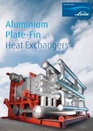
Left image shows the conventional construction of a<br />
finned tube with star-shape cross-section; right image<br />
shows the “duplex”-design consisting of an austenitic<br />
steel pipe inserted into a aluminium finned tube.<br />
In general air heated vaporisers consist of light<br />
metal tubes with longitudinal ribs (finned tubes<br />
with star-shaped cross-section). HQ-vaporiser<br />
are made in “duplex”-design, consisting of CrNisteel<br />
pipes inserted into aluminium finned tubes<br />
for increased transfer of heat.<br />
Factory-made, the inlet and outlet openings of<br />
the HQ-vaporiser are sealed gas-, dust- and<br />
moisture tight with shutter caps as well as in<br />
condition of low overpressure by protective gas.<br />
Inlet and outlet openings are sealed gas- and dust tight<br />
with caps, which must cut off prior installation. For highest<br />
purity and in order to avoid moisture tight in the<br />
course of carriage and stocking the HQ-vaporisers are<br />
delivered in condition of low overpressure by a protective<br />
gas.<br />
vaporiser type dimensions approx. weight empty<br />
nominal connections<br />
capacity* ) (inlet/outlet)<br />
design <strong>Linde</strong> ident-no.<br />
depth [m] widht [m] height[m] [kg] N 2 [Nm³/h] [mm] [mm]<br />
L 40 - 30 F 5,8 - HQ 1,84 1,54 6,976 960 660<br />
pipe: DN 40<br />
L06453<br />
L 40 - 24 F 5,8 - HQ 1,84 1,24 6,976 796 530<br />
(48,3 x 2)<br />
material:<br />
N23418<br />
L 40 - 16 F 5,8 - HQ 1,24 1,24 6,976 550 340<br />
stainless steel<br />
“duplex”<br />
N47708<br />
(CrNi-steel pipes<br />
L 40 - 16 F 4 - HQ 1,24 1,24 5,106 399 230 inserted into<br />
N47706<br />
L 40 - 12 F 4 - HQ 1,24 0,94 5,106 312 170<br />
aluminium<br />
pipe: DN 15<br />
finned tubes)<br />
(21,3 x 2)<br />
N53823<br />
L 40 - 8 F 3 - HQ 1,12 0,72 3,826 139 85<br />
material:<br />
stainless steel<br />
N47675<br />
L 40 - 4 F 3 - HQ 0,52 0,52 3,836 72 40 N43865<br />
*) The capacity is based on an ambient temperature of 20°C, 70 % rel. humidity, 15°C temperature difference between ambient and gas outlet temperature at a continuous 8-hours-operation
Type L 40 - 30 F 5,8 - HQ still without connecting piping<br />
between the finned tubes. At all time during fabrication<br />
internal purity is guaranteed by protective covers.<br />
9
10<br />
HD-standard design.<br />
The Special-VAP HD standard design is specially<br />
designed for high pressure use.<br />
The vaporisers are suitable for a design overpressure<br />
= max. allowable working pressure (PS)<br />
of 400 bar and a allowable operating temperature<br />
range (TS) of +50/-269°C.<br />
Design and testing was carried out in accordance<br />
with the directive 97/23/EC concerning pressure<br />
equipment, AD 2000-Merkblätter and DIN EN.<br />
Explanation of type designation:<br />
L = air heated<br />
400 = max. permissible working overpressure:<br />
400 bar<br />
8 F = number of Finned tubes: 8<br />
3 = length of single finned tube: 3 m<br />
HD = to be suitable for high pressure use<br />
Remark: standard vaporiser design is the<br />
long leg version (L = 900 mm)<br />
The material of the pipes, pipe bends and caps<br />
is corrosion-resistant austenitic CrNi-steel.<br />
HD-vaporiser are made in “duplex”-design, consisting<br />
of CrNi-steel pipes inserted into aluminium<br />
finned tubes for increased transfer of heat.<br />
For twenty years, we have offered<br />
vaporiser for high pressure use<br />
Factory-made, the inlet and outlet openings of<br />
the HD-vaporiser are sealed gas-, dust- and moisture<br />
tight with shutter caps.<br />
Just like the HQ-types the openings of the HD-vaporiser<br />
are sealed gas-, dust- and moisture tight with covers,<br />
which must cut off prior installation.<br />
vaporiser type dimensions approx. weight empty<br />
nominal connections<br />
capacity* ) (inlet/outlet)<br />
design <strong>Linde</strong> ident-no.<br />
depth [m] widht [m] height[m] [kg] N 2 [Nm³/h] [mm] [mm]<br />
L 400 - 30 F 5,8 - HD 1,84 1,54 6,976 957 660<br />
pipe: DN 15<br />
Q76115<br />
L 400 - 16 F 5,8 - HD 1,24 1,24 6,976 536 340<br />
(21,3 x 2,9)<br />
material:<br />
“duplex”<br />
Q28666<br />
L 400 - 8 F 3 - HD 1,12 0,72 3,826 139 85<br />
stainless steel<br />
Q76114<br />
*) The capacity is based on an ambient temperature of 20°C, 70% rel. humidity, 15 °C temperature difference between ambient and gas outlet temperature at a continuous 8-hours-operation
12<br />
Clip-on standard design.<br />
The vaporisers are suitable for a design overpressure<br />
= max. allowable working pressure (PS)<br />
of 40 bar and a allowable operating temperature<br />
range (TS) of +50/-196°C.<br />
Design and testing was carried out in accordance<br />
with the directive 97/23/EC concerning<br />
pressure equipment, AD 2000-Merkblätter and<br />
DIN EN.<br />
Explanation of type designation:<br />
L = air heated<br />
40 = max. permissible working overpressure:<br />
40 bar<br />
8 F = number of Finned tubes: 8<br />
2,5 = length of single finned tube: 2,5 m<br />
The <strong>Linde</strong> finned tubes and connecting flanges<br />
are made of aluminium alloy and the seals are<br />
formed according to <strong>Linde</strong> Standards.<br />
Clip-on standard design means the vaporiser<br />
without frame. As an option a mounting kit for<br />
installation on a cryo-tank is available on special<br />
request.<br />
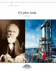
Type L 40 - 2 F 2,5<br />
Mounting kit<br />
Type L 40 - 4 F 2,5<br />
vaporiser type dimensions approx. weight empty<br />
nominal<br />
connections<br />
capacity* )<br />
(inlet/outlet)<br />
<strong>Linde</strong> ident-no.<br />
depth [m] widht [m] height[m] [kg] N 2 [Nm³/h] [mm]<br />
L 40 - 8 F 2,5 1,67 0,516 2,733 140 120<br />
screwed: M40 x 2<br />
J34895<br />
L 40 - 4 F 2,5 1,67 0,276 2,733 74 60<br />
pipe: DN 15 (21,3 x 1,5)<br />
socket welding end: ø18,2<br />
I32740<br />
L 40 - 2 F 2,5 0,69 0,276 2,709 37 30<br />
material: stainless steel<br />
I32631<br />
*) The capacity is based on an ambient temperature of 20°C, 70 % rel. humidity, 15°C temperature difference between ambient and gas outlet temperature at a continuous 8-hours-operation
14<br />
Pressure build-up.<br />
The vaporisers are suitable for a design overpressure<br />
= max. allowable working pressure<br />
(PS) of 40 bar and a allowable operating temperature<br />
range (TS) of +50/-196°C (HQ-type<br />
+50/-269°C).<br />
Design and testing was carried out in accordance<br />
with the directive 97/23/EC concerning<br />
pressure equipment, AD 2000-Merkblätter and<br />
DIN EN.<br />
Explanation of type designation:<br />
LD = air heated - pressure build-up<br />
40 = max. permissible working overpressure:<br />
40 bar<br />
5 F = number of Finned tubes: 5<br />
4 = length of single finned tube: 4 m<br />
HQ = to be suitable for Higher Quality fluids<br />
The <strong>Linde</strong> finned tubes and connecting flanges<br />
are made of aluminium alloy and the seals are<br />
formed according to <strong>Linde</strong> standards. The HQtype<br />
is made in “duplex”-design, consisting of<br />
CrNi-steel pipes inserted into aluminium finned<br />
tubes.<br />
Please take into consideration:<br />
The data on the performance - that is, the withdrawal<br />
quantity of the product gas - depend on<br />
the operating pressure, and must therefore be<br />
requested separately.<br />
Horizontal evaporators ensure high circulation forces.<br />
The image shows the types LD 40 - 5 F 4 and LD 40 - 5 F 2.<br />
* ) Allowable operating vaporiser type dimensions approx. weight empty<br />
external connections<br />
heat surface (inlet/outlet)<br />
design <strong>Linde</strong> ident-no.<br />
depth [m] widht [m] height [m] [kg] m 2 [mm] [mm]<br />
temperature range (TS) for +50/-269°C<br />
LD 40 - 5 F 4 4,174 0,655 0,58 44 8,8 pipe DN 25 (28 x 2)<br />
J46389<br />
for connection to<br />
LD 40 - 5 F 2 2,171 0,655 0,58 37 4,4 reducing braze-on Al-finned tubes J46390<br />
LD 40 - 4 F 1,6 1,25 0,5 2,085 90 13,3<br />
flange DN 40/25<br />
PN 40<br />
J46391<br />
LD 40 - 5F 2 - HQ 2,171 0,74 0,58 50,5 4,4 pipe DN 40 (48,3 x 2) “duplex” K47971<br />
LD 40 - 5F 4 - HQ 4,174 0,74 0,58 80 8,8 pipe DN 40 (48,3 x 2) “duplex” R56440<br />
LD 40 - 4 F 1,5 - HQ* ) 1,153 0,5 2,034 60 9,5 pipe: DN 40 (48,3 x 2) “duplex” 871321
16<br />
Operational efficiency.<br />
The nominal operational efficiency of the vaporiser<br />
is based on a reference ambient temperature<br />
of +20°C for N 2 (see tables of technical<br />
data). In this case, the difference in temperature<br />
between the ambient temperature and gas outlet<br />
is ≤15°C.<br />
The operational efficiency is dependent on<br />
various boundary conditions such as ambient<br />
temperature, wind velocity, air humidity, air<br />
circulation, ingress of sunlight, period of operation<br />
and the medium used.<br />
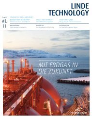
The following diagrams show how the nominal<br />
output is affected by the medium used (Fig. 1:<br />
Conversion factor), the ambient temperature<br />
(Fig. 2: Correction factor) and the period of<br />
operation (Fig. 3: Power factor).<br />
Note:<br />
As the boundary conditions are subject to large<br />
fluctuations, the information provided should be<br />
regarded as average, approximate values.<br />
In Fig. 4, calculations are shown by way of example<br />
for determining the anticipated nominal<br />
efficiency taking the operating medium, ambient<br />
temperature and period of operation into<br />
account.<br />
<strong>Air</strong> heated vaporisers have a modular construction<br />
principle and can be connected together<br />
individually according to the required output.<br />
The specified nominal performance figures apply<br />
to eight-hour permanent operation; after that,<br />
the performance of the vaporisers may drop<br />
because of frosting. For longer periods of operation<br />
it is therefore advisable to arrange the vaporiser<br />
modules in parallel. While one vaporiser<br />
group is working, the other vaporisers can regenerate.<br />
This prevents non-productive intermissions<br />
– gas withdrawal is assured at all times.<br />
medium<br />
conversion factor<br />
N 2 1<br />
Ar 1,15<br />
H 2 1,75<br />
O 2 0,92<br />
CH 4 0,76<br />
CO 2 0,33<br />
He 3,10<br />
Fig. 1: Conversion factor for the nominal efficiency<br />
of various media
Nominal output<br />
1.2<br />
Correction factor<br />
1.0<br />
0.8<br />
0.6<br />
0.4<br />
-30 -20 -10 0 10 20 30 40 50<br />
Ambient temperature [°C]<br />
Fig. 2: Correction factor - for the nominal operational efficiency as a function of ambient temperature<br />
Power factor<br />
1.4<br />
1.3<br />
1.2<br />
1.1<br />
1.0<br />
0.9<br />
0.8<br />
Nominal output<br />
0 2 4 6 8 10 12 14 16<br />
Operational duration [h]<br />
Fig. 3: Power factor - for the nominal operational efficiency as a function of operational duration<br />
Examples for vaporizer type L40 - 8F 3; nominal output at +20°C according to Fig. 1 = 130 Nm³/h:<br />
Example 1: For N 2 at +20°C and 8 h duration of operation:<br />
Nominal output = 100 % x conversion factor 1 x correction factor 1 x power factor 1 = 100 %<br />
i.e. nominal output (N 2 ) = 130 Nm³/h<br />
actual output (N 2 ) = 130 Nm³/h x factor 1 = 130 Nm³/h<br />
Example 2: For O 2 at -20°C and 2 h duration of operation:<br />
Nominal output = 100 % x conversion factor 0,92 x correction factor 0,6 x power factor 1,25 = 69 %<br />
i.e. nominal output (N 2 ) = 130 Nm³/h<br />
actual output (O 2 ) = 130 Nm³/h x factor 0,69 = 90 Nm³/h<br />
Fig. 4: Sample calculations for determining nominal output
18<br />
Know-how, quality, inspection,<br />
documentation.<br />
<strong>Linde</strong> is commited to customers satisfaction:<br />
The only acceptable standard by which we can<br />
measure quality success.<br />
Our customers expect us to supply safe and<br />
reliable plants and components which operate<br />
both economically and in an environmentally<br />
friendly manner, reflecting the current state<br />
of technology.<br />
Since a period of almost half a century <strong>Linde</strong><br />
designs and manufactures air-heated vaporisers<br />
for cryogenic applications.<br />
The new range of Lead- and Special-Vaporiser is<br />
a direct result of our ongoing product development.<br />
They conform to the latest technical<br />
standards, are proven, effective in performance<br />
and simple to use.<br />
There is a permanent on-site-support by the notified body.<br />
A view from above into the blades of a vaporiser shows<br />
the detailed sophistication of the technology. The new<br />
type of vaporiser is characterised by improved power,<br />
compared with the previous model.
19<br />
Quality management is an indispensable<br />
part of our corporate strategy and therefore<br />
a managerial responsibility carried out at all<br />
levels of the company.<br />
Extensive testing ensures the highest welding<br />
quality and safety. The inspections will be carried<br />
out by applying the directives and operating<br />
instructions of the <strong>Linde</strong> quality managementsystem<br />
as well as supervised by the independent<br />
official notified body.<br />
The cleanliness of our products, even oxygen<br />
applications, naturally conforms to the purity<br />
requirements of the EN 12300 standard.<br />
Because of the pressures that they will be subjected<br />
to in later operation, and the associated<br />
risks, units like vaporisers are subject to stringent<br />
manufacturing requirements.<br />
All named vaporiser types of these prospectus<br />
comply with the essential safety requirements<br />
defined in Annex I of directive 97/23/EC concerning<br />
pressure equipment.<br />
Each delivered CE vaporiser is unambiguously<br />
documented by the EC declaration of conformity,<br />
issued by <strong>Linde</strong> and related to the fabrication<br />
number. The associated operating instructions<br />
contain a type-relevant data sheet.<br />
Every vaporiser must meet the demands of the required<br />
proof test. The final inspection and pressure test are performed<br />
exclusively by trained and responsible qualified<br />
personnel and monitored by the Notified Body.<br />
<strong>Linde</strong> vaporisers for air-heated gas transformation<br />
– safe, reliable supply made to measure.<br />
All measuring instruments are calibrate and checked<br />
periodically.<br />
Each vaporiser can be identified by a name plate with its<br />
rating, CE seal, the identification number of the notified<br />
body responsible for monitoring/acceptance, and an individual<br />
fabrication number.
20<br />
Documentation<br />
EC Declaration of Conformity; the associated<br />
operating instructions contain a type-relevant<br />
data sheet, which includes information among<br />
other things on attachment to foundations.<br />
The <strong>Engineering</strong> Division, Schalchen Plant<br />
is certified of a Quality Management System<br />
according to ISO 9001.
21<br />
COMPLIES PROVISIONS ACC.<br />
TO DIRECTIVE CONCERNING<br />
PRESSURE TREATMENT<br />
97/23/EC<br />
MONITORED<br />
OR<br />
FINAL ASSESSMENT<br />
BY NOTIFIED BODY<br />
QUALITY<br />
MANAGEMENT SYSTEM<br />
ACC. TO<br />
EN ISO 9001<br />
QUALITY<br />
CLEANLINESS<br />
LINDE KNOW-HOW<br />
EN 12300 - O 2<br />
LINDE KNOW-HOW<br />
OF<br />
CRYOGENIC PRESSURE<br />
VESSELS<br />
COMPLIES REQUIREMENTS<br />
OF CLEANLINESS FOR<br />
CRYOGENIC SERVICE;<br />
OXYGEN SERVICE
22<br />
SHEQ - safety, health, environment<br />
and quality police.<br />
At the <strong>Engineering</strong> Division, we do not want to<br />
harm people or the environment. We will comply<br />
with all applicable legal, regulatory, internal<br />
and industry requirements.<br />
We strive to be leading in SHEQ to meet safe,<br />
secure and healthy working conditions and<br />
supplying safe, compliant and environmentally<br />
responsible products and services for our<br />
customers.<br />
SHEQ is a key part of The <strong>Linde</strong> Group’s overall<br />
strategy and we will also require our contractors<br />
and partners to manage in line with this<br />
policy.<br />
To achieve this vision,<br />
SHEQ is 100 % of our<br />
behaviour,<br />
100 % of the time.
23<br />
Service and guarantee.<br />
Welcome to the <strong>Engineering</strong> Division<br />
The <strong>Linde</strong> Schalchen Plant is located 100 km<br />
east of Munich, Germany. 700 engineers and<br />
skilled workers design and manufacture components<br />
and complete modules for the application<br />
in process plants.<br />
Backed up by more than 100 years of production<br />
know-how, highly developed plant<br />
modules are manufactured. Our innovative<br />
technologies and our competitiveness open<br />
the door to participation in prestigious plant<br />
projects worldwide.<br />
<strong>Linde</strong> provides complete services on field installation<br />
and operation. A specialised service crew<br />
is available for immediate and professional repair<br />
services.<br />
Do you need further and more detailed<br />
information<br />
Just ask us – we will be pleased to help you.<br />
<strong>Linde</strong> AG<br />
<strong>Engineering</strong> Division<br />
Schalchen Plant<br />
Carl-von-<strong>Linde</strong>-Strasse 15<br />
83342 Tacherting/Germany<br />
Phone +49.8621.85-0 (center)<br />
Fax +49.8621.85-6628<br />
E-Mail plantcomponents@linde-le.com<br />
Internet www.linde.de<br />
Production area<br />
of standardised equipment:<br />
– Advice and sale<br />
Phone: +49.8621.85-6689<br />
– After sales service, guarantee<br />
Phone: +49.8621.85-6279<br />
– Office for the distribution of orders<br />
Phone: +49.8621.85-6432<br />
Other products by production area<br />
of standardised equipment:<br />
– Static vacuum insulated cryogenic vessels<br />
– Spiral welded pipes
Designing processes – constructing plants.<br />
<strong>Linde</strong>´s <strong>Engineering</strong> Division continuously develops extensive process engineering know-how in the planning,<br />
project management and construction of turnkey industrial plants.<br />
The range of products comprises:<br />
− Petrochemical plants<br />
− LNG and natural gas processing plants<br />
− Synthesis gas plants<br />
− Hydrogen plants<br />
− Gas processing plants<br />
− Adsorption plants<br />
− <strong>Air</strong> separation plants<br />
− Cryogenic plants<br />
− Biotechnology plants<br />
− Furnaces for petrochemical plants and refineries<br />
More than 4,000 plants worldwide document the leading position of the <strong>Engineering</strong> Division in international<br />
plant construction.<br />
Production facilities.<br />
At <strong>Linde</strong> <strong>Engineering</strong> Schalchen Plant over 700<br />
skilled engineers and workers design and manufacture<br />
components and complete modules for<br />
numerous applications in process plants such as<br />
ethylene plants, hydrogen and synthesis gas<br />
plants, LNG plants and air separation plants. Production<br />
capacity totals approx. 1.3 million hours<br />
per year.<br />
In addition, the plant offers services for field installation<br />
and advice on operation. A specialised<br />
service crew is available for immediate and professional<br />
repair services.<br />
Product range.<br />
– Aluminium plate-fin heat exchangers as<br />
single units or as manifolded assemblies<br />
– Cold boxes with aluminium plate-fin heat<br />
exchangers, columns and vessels<br />
– Coil-wound heat exchangers and isothermal<br />
reactors for chemical and petrochemical<br />
plants<br />
– Columns and pressure vessels in aluminium<br />
for cryogenic plants<br />
– Spiral-welded pipes in aluminium<br />
– Storage tanks for liquefied gases<br />
– Steam-heated waterbath vaporisers as well<br />
as air-heated vaporisers for liquefied gases<br />
For further informations please contact:<br />
<strong>Linde</strong> AG<br />
<strong>Engineering</strong> Division, Schalchen Plant<br />
Carl-von-<strong>Linde</strong>-Strasse 15, 83342 Tacherting, Germany<br />
Phone +49.8621.85-6434, Fax +49.8621.85-6622<br />
E-Mail: plantcomponents@linde-le.com, www.linde-plantcomponents.com<br />
P/3.4.e/12