am-240320lftnqw-00h - Amp Displays
am-240320lftnqw-00h - Amp Displays
am-240320lftnqw-00h - Amp Displays

Create successful ePaper yourself
Turn your PDF publications into a flip-book with our unique Google optimized e-Paper software.
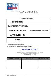
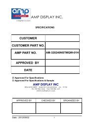
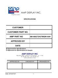
AMP DISPLAY INC.<br />
CUSTOMER<br />
SPECIFICATIONS<br />
CUSTOMER PART NO.<br />
AMPIRE PART NO.<br />
AM-240320LFTNQW-00H<br />
APPROVED BY<br />
DATE<br />
Approved For Specifications<br />
Approved For Specifications & S<strong>am</strong>ple<br />
AMP DISPLAY INC<br />
9856 SIXTH STREET RANCHO CUCAMONGA CA 91730<br />
TEL: 909-980-13410 FAX: 909-980-1419<br />
WWW.AMPDISPLAY.COM<br />
APPROVED BY CHECKED BY ORGANIZED BY<br />
Date : 2011/12/05 1
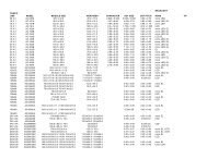
RECORD OF REVISION<br />
Revision Date Page Contents Editor<br />
2010/10/21<br />
-<br />
New Release<br />
Emil<br />
2011/03/15<br />
5<br />
Add information of PWM control<br />
Kevin<br />
11<br />
Correct the description of IC Power Voltage<br />
Kevin<br />
2011/05/20<br />
10<br />
Correct the Block diagr<strong>am</strong><br />
Kevin<br />
2011/12/05<br />
-<br />
Refine the SPEC<br />
Kevin<br />
Date : 2011/12/05 2
1 Features<br />
LCD 2.4 inch Amorphous-TFT-LCD (Thin Film Transistor Liquid Crystal Display)<br />
for mobile-phone or handy electrical equipments.<br />
(1) Construction: 2.4” a-Si color TFT-LCD, White LED Backlight and FPCB.<br />
(2) Main LCD : 2.1 Amorphous-TFT 2.4 inch display, Normally black type (MVA).<br />
2.2 240(RGB) X320 dots Matrix, 1/320 Duty.<br />
2.3 Narrow-contact ledge technique.<br />
2.4 Main LCD Driver IC: HX8347-D<br />
2.5 262K: Red-6bit, Green-6bit, Blue-6bit (18-bit interface)<br />
(3) Low cross talk by fr<strong>am</strong>e rate modulation<br />
(4) Direct data display with display RAM<br />
(5) Partial display function: You can save power by limiting the display space.<br />
(6) Interface: MPU and RGB Interface. (Select by H/W Jumper). Default : SPI<br />
JP0(IM0) JP1(IM1) JP2(IM2) JP3(IM3) Remark<br />
Interface mode R1(H) R2(L) R3(H) R4(L) R5(H) R6(L) R7(H) R8(L)<br />
80-16BIT Type I NC 0R NC 0R NC 0R NC 0R<br />
80-8BIT Type I 0R NC NC 0R NC 0R NC 0R<br />
80-16BIT Type II NC 0R 0R NC NC 0R NC 0R<br />
80-8BIT Type II 0R NC 0R NC NC 0R NC 0R<br />
3-wire SPI NC 0R NC 0R 0R NC NC 0R Default<br />
4-wire SPI - - 0R NC 0R NC NC 0R<br />
80-18BIT Type I NC 0R NC 0R NC 0R 0R NC<br />
80-9BIT Type I 0R NC NC 0R NC 0R 0R NC<br />
80-18BIT Type II NC 0R 0R NC NC 0R 0R NC<br />
80-9BIT Type II 0R NC 0R NC NC 0R 0R NC<br />
(7) Abundant command functions:<br />
Area scroll function<br />
Display direction switching function<br />
Power saving function<br />
Electric volume control function: you are able to progr<strong>am</strong> the temperature<br />
compensation function.<br />
Date : 2011/12/05 3
2 Mechanical specifications<br />
Dimensions and weight<br />
Item Specifications Unit<br />
External shape dimensions 43.6 (W) x 101.33 (H) x3.85(T) mm<br />
Pixel size 0.153 (W) x 0.153 (H) mm<br />
Main<br />
LCD<br />
Active area 36.72 (W) x 48.96 (H) mm<br />
Number of Pixels 240(H)x320(V) pixels mm<br />
Weight TBD g<br />
*1. This specification is about External shape on shipment from AMPIRE.<br />
3 Absolute max. ratings and environment<br />
3-1 Absolute max. ratings<br />
Ta=25 o C GND=0V<br />
Item Symbol Min. Max. Unit Remarks<br />
Power voltage V DD -0.3 +3.3 V<br />
Input voltage V IN -0.5 V DD V Note(1)<br />
Backlight voltage V AK -0.5 14 V Serial<br />
LED driving voltage V LED -0.5 6 V<br />
Note(1) : Input voltage at ant terminal.<br />
3-2 Environment<br />
Item Specifications Remarks<br />
Storage temperature<br />
Max. +80 o C Note 1:<br />
Min. -30 o C<br />
Non-condensing<br />
Operating temperature<br />
Max. +70 o C Note 1:<br />
Min. -20 o C<br />
Non-condensing<br />
Note 1:Ta ≦+40<br />
o C・・・・Max.85%RH<br />
Ta>+40 o C・・・・The max. humidity should not exceed the<br />
humidity with 40 o C 85%RH.<br />
Date : 2011/12/05 4
4 Electrical specifications<br />
4-1 Electrical characteristics of LCM<br />
(V DD =2.8V, Ta=25 o C)<br />
Item Symbol Conditions Min. Typ. Max. Unit<br />
Power voltage V DD - 2.6 2.8 3.3 V<br />
High-level input<br />
voltage<br />
Low-level input<br />
voltage<br />
V IH - 0.8 - V DD V<br />
V IL - -0.3 - 0.2V DD V<br />
Consumption<br />
current of VDD<br />
I DD<br />
LED off/<br />
white pattern<br />
- 8 - mA<br />
4-2 LED back light specification<br />
(V DD =2.8V, Ta=25 o C)<br />
Item Symbol Conditions Min. Typ. Max. Unit Note<br />
Backlight voltage V AK I AK =20mA 12.5 12.8 13.6 V (1)<br />
Forward current I AK 4-chip serial - 20 25 mA (1)<br />
Power consumption P AK<br />
I AK =20mA ,<br />
without LED - 260 - mW (1)<br />
driver<br />
LED driving voltage V LED - 3.3 5.0 6.0 V (2)<br />
PWM voltage V ADJ - 3.0 3.3 4.0 V -<br />
PWM Frequency F PWM V ADJ = 5.0V 100 - 200K Hz (2)<br />
Luminous color White -<br />
Chip connection 4 chip serial connection -<br />
Note (1) : LED backlight only , without LED Driver.<br />
Note (2) : Only if LED driver included.<br />
A<br />
5/6 A<br />
1/6 B<br />
1/2 A<br />
1/6 A<br />
1 2 3<br />
B<br />
5/6 B<br />
1/2 B<br />
4 5 6<br />
7 8 9<br />
Light source<br />
(MAIN LCD)<br />
Date : 2011/12/05 5
A A<br />
K K K<br />
Date : 2011/12/05 6
5 Main LCD<br />
5-1 Optical characteristics<br />
(1/320 Duty in case except as specified elsewhere Ta = 25°C)<br />
Item Symbol Temp Min. Typ. Max. Unit Conditions<br />
Response time<br />
Tr 25 o C - 15 25<br />
Tf 25 o C - 20 30<br />
Contrast ratio CR 25 o C - 450 - -<br />
ms<br />
θ=0 o゜,φ=0 o<br />
(Note 2)<br />
θ=0 o , φ=0 o LED:ON,<br />
LIGHT:OFF<br />
(Note 4)<br />
Transmittance T 25 o C - 4.7 - % -<br />
Visual angle<br />
range front and<br />
rear<br />
θ<br />
25 o C<br />
(θf) 80<br />
(θb) 80<br />
degree<br />
φ= 0 o , CR≧10 LED:ON<br />
LIGHT:OFF<br />
(Note 3)<br />
Visual angle<br />
range left and<br />
right<br />
θ<br />
25 o C<br />
(θl) 80<br />
(θr) 80<br />
degree<br />
φ=90 o , CR≧10 LED:ON<br />
LIGHT:OFF<br />
(Note 3)<br />
Brightness - - 300 400 - cd/m 2 I F=20mA, Full White<br />
pattern<br />
5-2 CIE (x, y) chromaticity (1/320 Duty Ta = 25°C)<br />
Item<br />
Red<br />
Green<br />
Blue<br />
White<br />
Symbol<br />
Color coordinate<br />
Min. Typ. Max.<br />
X 0.59 0.64 0.69<br />
Y 0.29 0.34 0.39<br />
X 0.29 0.34 0.39<br />
Y 0.57 0.62 0.67<br />
X 0.09 0.14 0.19<br />
Y 0.01 0.06 0.11<br />
X 0.25 0.30 0.35<br />
Y 0.27 0.32 0.37<br />
Conditions<br />
θ=0゜,φ=0゜<br />
θ=0゜,φ=0゜<br />
θ=0゜,φ=0゜<br />
θ=0゜,φ=0゜<br />
NOTE 1: Optical characteristic Ring measurement light system<br />
LCD module<br />
Brightness gauge<br />
BM-7 (Topcon)<br />
Glass fiber<br />
LED:OFF, LIGHT:ON<br />
Metal halide l<strong>am</strong>p<br />
Date : 2011/12/05 7
LCD<br />
Optical Detector<br />
Brightness gauge<br />
BM-7 (Topcon)<br />
LED<br />
LED:ON, LIGHT:OFF<br />
NOTE 2: Response time definition<br />
NOTE 3: φ、θ definition<br />
Date : 2011/12/05 8
NOTE 4: Contrast definition<br />
NOTE 5: Visual angle direction priority<br />
12 : 00<br />
9 : 00 8 8 8 8<br />
3 : 00<br />
6 : 00<br />
Date : 2011/12/05 9
6 Block Diagr<strong>am</strong><br />
Block diagr<strong>am</strong> (Main LCD)<br />
Display format: A-Si TFT transmissive, Normally black type (MVA).<br />
Display composition: 240 x RGB x 320 dots<br />
LCD Driver : HX8347-D<br />
Date : 2011/12/05 10
7 Interface specifications<br />
Pin No. Terminal Functions<br />
1 NC No connection<br />
2 NC No connection<br />
3 VADJ For LED Driver IC Dimming; Keep Hi for LED ON.<br />
4 VLED Power supply for LED Driver IC circuit.<br />
5<br />
6<br />
7<br />
NC No connection.<br />
8<br />
9 GND Power ground.<br />
10 DB0<br />
11 DB1<br />
12 DB2<br />
Mode IM[3:0] PD Pin in use<br />
13 DB3 MCU 18-bit Type I 1000 PD [17:0]<br />
MCU 16-bit Type I 0000 PD [15:10]<br />
14 DB4 MCU 9-bit Type I 1001 PD [8:0]<br />
15 DB5 MCU 8-bit Type I 0001 PD [7:0]<br />
16 DB6 MCU 18-bit Type II 1010 PD [17:0]<br />
MCU 16-bit Type II 0010 PD [17:10], DB[8:1]<br />
17 DB7<br />
MCU 9-bit Type II 1011 PD [17:9]<br />
18 DB8 MCU 8-bit Type II 0011 PD [17:10]<br />
19 DB9<br />
SDI, SDO, SCL<br />
20 DB10 Serial Mode/Digital<br />
R[5:0]=PD[17:12]<br />
0101<br />
RGB Interface Mode<br />
G[5:0]=PD[11:6]<br />
21 DB11<br />
B[5:0]=PD[5:0]<br />
22 DB12<br />
23 DB13<br />
24 DB14<br />
25 DB15<br />
26 DB16<br />
27 DB17<br />
28 SDI Serial bus interface data input pin.<br />
29 WR/SDL Write enable signal/Serial bus interface clock input pin.<br />
30 /RD Read enable signal.<br />
31 /RESET Reset pin. Setting either pin low initializes the LSI.<br />
Must be reset the chop after power being supplied.<br />
32 DE A data ENABLE signal in RGB I/F mode.<br />
33 GND Power ground.<br />
34 DCLK Dot clock signal in RGB I/F mode.<br />
35 GND Power ground.<br />
36 HSYNC Line synchronizing signal in RGB I/F mode.<br />
37 VSYNC Fr<strong>am</strong>e synchronizing signal in RGB I/F mode.<br />
38 /CS Chip select signal.<br />
39 RS Command/display Data Selection.<br />
40 VDD Power voltage.<br />
Date : 2011/12/05 11
7-1 Parallel bus system interface<br />
The input / output data from data pins (DB17-0) and signal operation of the I80<br />
series parallel bus interface are listed as below.<br />
Operations WR/SCL /RD RS<br />
Writes Indexes into IR 0 1 0<br />
Reads internal status 1 0 0<br />
Writes command into register or data into GRAM 0 1 1<br />
Reads command from register or data from GRAM 1 0 1<br />
Write to register<br />
/CS<br />
RS<br />
/RD<br />
/WR<br />
DB0~DB7<br />
Index write to<br />
index register<br />
Command write to<br />
register<br />
Read to register<br />
/CS<br />
RS<br />
/RD<br />
/WR<br />
DB0~DB7<br />
Index write to<br />
index register<br />
Command read to<br />
register<br />
Date : 2011/12/05 12
Write to the graphic RAM<br />
/CS<br />
RS<br />
/RD<br />
/WR<br />
Data<br />
Bus<br />
22h<br />
1st write<br />
data<br />
2nd write<br />
data<br />
3rd write<br />
data<br />
4th write<br />
data<br />
5th write<br />
data<br />
Read to the graphic RAM<br />
/CS<br />
RS<br />
/WR<br />
/RD<br />
Data<br />
Bus<br />
22h<br />
Dummy<br />
read<br />
1st read<br />
data<br />
2nd read<br />
data<br />
3rd read<br />
data<br />
4th read<br />
data<br />
Date : 2011/12/05 13
7-2 MCU data color coding<br />
MCU Data Color Coding for RAM data Write<br />
Date : 2011/12/05 14
7-3 80-system 18-bit interface<br />
The I80-system 18-bit parallel bus interface type I in command-par<strong>am</strong>eter<br />
interface mode can be used by setting external pins “IM3, IM2, IM1, IM0” pins to<br />
“1000”. And the I80-system 18-bit parallel bus interface type II in<br />
command-par<strong>am</strong>eter interface mode can be used by setting ““IM3, IM2, IM1, and<br />
IM0”pins to“1010”. Figure 5.3 is the ex<strong>am</strong>ple of interface with I80 microcomputer<br />
system interface.<br />
Date : 2011/12/05 15
7-4 80-system 16-bit interface<br />
The I80-system 16-bit parallel bus interface type I in command-par<strong>am</strong>eter interface<br />
mode can be used by setting external pins ““IM3, IM2, IM1, IM0” pins to “0000”.<br />
And I80-system 16-bit parallel bus interface type II in command-par<strong>am</strong>eter<br />
interface mode can be used by setting ““IM3, IM2, IM1, IM0” pins to “0010”. Figure<br />
5.5 is the ex<strong>am</strong>ple of type I interface with I80 microcomputer system interface. And<br />
Figure 5.6 is the ex<strong>am</strong>ple of type II interface with I80 microcomputer system<br />
interface.<br />
Date : 2011/12/05 16
Date : 2011/12/05 17
Date : 2011/12/05 18
7-5 9-bit parallel bus system interface<br />
The I80-system 9-bit parallel bus interface type I in command-par<strong>am</strong>eter interface<br />
mode can be used by setting external pins ““IM3, IM2, IM1, IM0” pins to “1001”.<br />
And I80-system 9-bit parallel bus interface type II in command-par<strong>am</strong>eter interface<br />
mode can be used by setting ““IM3, IM2, IM1, IM0” pins to “1011”. Figure 5.15 is<br />
the ex<strong>am</strong>ple of type I interface with I80 microcomputer system interface. And<br />
Figure 5.16 is the ex<strong>am</strong>ple of type II interface with I80 microcomputer system<br />
interface.<br />
Date : 2011/12/05 19
7-6 8-bit Parallel Bus System Interface<br />
The I80-system 8-bit parallel bus interface type I in command-par<strong>am</strong>eter interface<br />
mode can be used by setting external pins ““IM3, IM2, IM1, IM0” pins to “0001”.<br />
And I80-system 8-bit parallel bus interface type II in command-par<strong>am</strong>eter interface<br />
mode can be used by setting ““IM3, IM2, IM1, IM0” pins to “0011”. Figure 5.19 is<br />
the ex<strong>am</strong>ple of type I interface with I80 microcomputer system interface. And<br />
Figure 5.20 is the ex<strong>am</strong>ple of type II interface with I80 microcomputer system<br />
interface.<br />
Date : 2011/12/05 20
Date : 2011/12/05 21
7-7 MCU Data Color Coding for RAM data Read<br />
Date : 2011/12/05 22
Date : 2011/12/05 23
7-8 Serial bus system interface<br />
The HX8347-D supports two kinds of serial bus interface in register-content mode<br />
by setting external pins “IM2, IM1” pins to “10” 3-wire serial interface and “IM2,<br />
IM1” pins to “11” 4-wire serial interface. The serial bus system interface mode is<br />
enabled through the chip select line (/CS), and it is accessed via a control<br />
consisting of the serial input data (SDA), and the serial transfer clock signal<br />
(WR/SCL).<br />
7-8-1 3-wire serial interface<br />
As the chip select signal (NCS) goes low, the start byte needs to be transferred first.<br />
The start byte is made up of 6-bit bus device identification code; register select (RS)<br />
bit and read/write operation (RW) bit. The five upper bits of 6-bit bus device<br />
identification code must be set to “01110”, and the least significant bit of the<br />
identification code must be set as the external pin IM0 input as “ID”.<br />
The seventh bit (RS) of the start byte determines internal index register or register,<br />
GRAM accessing. RS must be set to “0” when writing data to the index register or<br />
reading the status and it must be set to “1” when writing or reading a command or<br />
GRAM data. The read or write operation is selected by the eighth bit (RW) of the<br />
start byte. The data is written to the chip when R/W = 0, and read from chip when<br />
RW = 1.<br />
Date : 2011/12/05 24
Date : 2011/12/05 25
Date : 2011/12/05 26
7-8-2 4-wire serial interface<br />
4-pin serial case, data packet contains just transmission byte and control bit DNC<br />
is transferred by DNC pin. If DNC is low, the transmission byte is command byte. If<br />
DNC is high, the transmission byte is stored to index register or GRAM. The MSB<br />
is transmitted first. The serial interface is initialized when NCS is high. In this state,<br />
NWR_SCL clock pulse or SDA data have no effect. A falling edge on NCS enables<br />
the serial interface and indicates the start of data transmission.<br />
Date : 2011/12/05 27
7-9 RGB Interface<br />
The HX8347-D uses RCM [1:0] =’10’ or ‘11’ hardware setting to select RGB<br />
interface. After Power on Sequence, the RGB interface is activated. When RCM<br />
[1:0] =’10’ use VSYNC, HSYNC, DE, DOTCLK, DB17-0 parallel lines for the RGB<br />
interface (RGB mode 1). When RCM [1:0] =’11’ use VSYNC, HSYNC, DOTCLK,<br />
DB17-0 parallel lines for the RGB interface (RGB mode 2).<br />
Pixel clock (DOTCLK) must be running all the time without stopping and it is used<br />
to entering VSYNC, HSYNC, DE and DB17-0 lines states when there is a rising<br />
edge of the DOTCLK.<br />
In RGB interface mode 1, the valid display data is inputted in pixel unit via DB17-0<br />
according to the high-level(‘H’) of DE signal, and display operations are executed in<br />
synchronization with the fr<strong>am</strong>e synchronizing signal (VSYNC), line synchronizing<br />
signal (HSYNC) and pixel clock (DOTCLK). In RGB interface mode 2, the valid<br />
display data is inputted in pixel unit via DB17-0 according to the HBP setting of<br />
HSYNC signal, and the VBP setting of VSYNC. In these two RGB interface modes,<br />
the input display data is not written to GRAM and is displayed directly.<br />
Vertical synchronization (VSYNC) signal is used to tell when there a new fr<strong>am</strong>e of<br />
the display is received, and this is negative (‘-‘, ‘0’, low) active. Horizontal<br />
synchronization signal (HSYNC) is used to tell when a new line of the fr<strong>am</strong>e is<br />
received, and this is negative (‘-‘, ‘0’, low) active. Data enable (DE) is used to tell<br />
when RGB information is received that should be transferred on the display, and<br />
this is positive (‘+’, ‘1’, high) active. DB17-0 are used to tell what the information of<br />
the image is, that is transferred on the display when DE=’H’.<br />
Date : 2011/12/05 28
The image information is correct on the display when the timings are in range on<br />
the interface. However, the image information will be incorrect on the display, when<br />
timings are out of the range on the RGB interface and the correct image<br />
information will be displayed automatically (by the display module) on the next<br />
fr<strong>am</strong>e (vertical sync.), when there is returned from out of the range to in range RGB<br />
interface timings.<br />
Date : 2011/12/05 29
All 3 kinds of bus width can be available during RGB interface mode (selected by<br />
COLMOD (17H) command for 6-bit, 16-bit and 18-bit data width)<br />
Date : 2011/12/05 30
RGB interface mode<br />
There are 2 kinds of RGB mode which is selected by RCM1 & RCM0 hardware<br />
pins.<br />
In RGB Mode 1 (RCM1, RCM0 = “10”), writing data to display is done by DOTCLK<br />
and Video Data Bus (DB [17:0]), when DE is high state. The external<br />
synchronization signals (DOTCLK, VS and HS) are used for internal display signals.<br />
So, controller (host) must always transfer DOTCLK, VS, HS and DE signals to<br />
driver.<br />
In RGB Mode 2 (RCM1, RCM0 = “11”), blanking porch setting of VS and HS<br />
signals are defined by R33h and R34h command. DE pin is not used.<br />
7-10 Color order on RGB interface<br />
The meaning of the pixel information, when 3 components/pixel (Red, Green and<br />
Blue) on RGB interface are used, is describing on the following table:<br />
Date : 2011/12/05 31
7-11 RGB data color coding<br />
18-bits/pixel Colors Order on 6-bit Data width RGB Interface (RGB 6-6-6-bit input).<br />
There is 1 pixel (3 sub-pixels) per 3 bytes, 262K-colors, 17H=”E0h”<br />
Date : 2011/12/05 32
16-bits/pixel Colors Order on the 16-bits Data width RGB Interface (RGB 5-6-5-bits<br />
input). There is 1 pixel (3 sub-pixels) per byte, 65K-colors, 17H=”50h”<br />
Date : 2011/12/05 33
18-bits/pixel Colors Order on the 18-bit Data width RGB Interface (RGB 6-6-6-bit<br />
input). There is 1 pixel (3 sub-pixels) per byte, 262K-colors, 17H=”60h”<br />
Date : 2011/12/05 34
7-12 Instruction List<br />
LCD Driver/Controller IC:HX8347-D<br />
Date : 2011/12/05 35
Date : 2011/12/05 36
Date : 2011/12/05 37
8 Application<br />
8-1 Display ON / OFF<br />
Date : 2011/12/05 38
8-2 Standby mode<br />
Date : 2011/12/05 39
8-3 Deep Standby mode<br />
Date : 2011/12/05 40
8-4 Power ON/OFF setting flow<br />
Date : 2011/12/05 41
9 Electrical Characteristics<br />
9-1 AC Characteristics<br />
Date : 2011/12/05 42
Date : 2011/12/05 43
Date : 2011/12/05 44
Date : 2011/12/05 45
Date : 2011/12/05 46
10 QUALITY AND RELIABILITY<br />
1. Scope<br />
Specifications contain<br />
1.1 Display Quality Evaluation<br />
1.2 Mechanics Specification<br />
2. S<strong>am</strong>pling Plan<br />
Unless there is other agreement, the s<strong>am</strong>pling plan for incoming inspection<br />
shall<br />
follow MIL-STD-105E LEVEL II.<br />
2.1 Lot size: Quantity per shipment as one lot (different model as different lot ).<br />
2.2 S<strong>am</strong>pling type: Normal inspection, single s<strong>am</strong>pling.<br />
2.3 S<strong>am</strong>pling level: Level II.<br />
2.4 AQL: Acceptable Quality Level<br />
Major defect: AQL=0.65<br />
Minor defect: AQL=1.0<br />
3. Panel Inspection Condition<br />
3.1 Environment:<br />
Room Temperature: 25±5°C.<br />
Humidity: 65±5% RH.<br />
Illumination: 300 ~ 700 Lux.<br />
3.2 Inspection Distance:<br />
35-40 cm<br />
3.3 Inspection Angle:<br />
The vision of inspector should be perpendicular to the surface of the<br />
Module.<br />
3.4 Inspection time:<br />
Perceptibility Test Time: 20 seconds max.<br />
4. Display Quality<br />
4.1 Function Related:<br />
The function defects of line defect, abnormal display, and no display are<br />
considered Major defects.<br />
Date : 2011/12/05 47
4.2 Bright/Dark Dots:<br />
Defect Type / Specification G0 Grade A Grade<br />
Bright Dots 0 0<br />
Dark Dots 0 N2<br />
Total Bright and Dark Dots 0 N2<br />
[Note 1]<br />
Judge defect dot and adjacent dot as following.<br />
(1) One pixel consists of 3 sub-pixels, including R,G, and B dot.(Sub-pixel = Dot)<br />
(2) The definition of dot: The size of a defective dot over 1/2 of whole dot is<br />
regarded as one defective dot.<br />
(3) Allow above (as A, B, C and D status) adjacent defect dots, including bright and<br />
dart adjacent dot. And they will be counted 2 defect dots in total quantity.<br />
(4) Defects on the Black Matrix, out of Display area, are not considered as a defect<br />
or counted.<br />
(5) There should be no distinct non-uniformity visible through 6% ND Filter within 2<br />
sec inspection times.<br />
4.3 Visual Inspection specifications:<br />
Defect Type Specification Count(N)<br />
Dot Shape<br />
(Particle、Scratch and Bubbles in<br />
display area)<br />
Line Shape<br />
(Particles、Scratch、Lint and<br />
Bubbles in display area)<br />
D0.1mm<br />
Ignored<br />
0.1mm0.3mm N=0<br />
W0.03mm<br />
Ignored<br />
0.03mm0.1mm, L>2.5mm N=0<br />
Date : 2011/12/05 48
[Note 2] W : Width[mm], L : Length[mm], N : Number, φ : Average Di<strong>am</strong>eter<br />
[Note 3] Bright dot is defined through 6% transmission ND Filter as following.<br />
5. Reliability and Test Conditions<br />
ITEM<br />
HIGH TEMPERATURE OPERATION<br />
HIGH TEMPERATURE AND HIGH HUMIDITY<br />
OPERATION<br />
HIGH TEMPERATURE STORAGE<br />
LOW TEMPERATURE OPERATION<br />
LOW TEMPERATURE STORAGE<br />
THERMAL SHOCK<br />
CONDITIONS<br />
70℃ , 240Hrs<br />
60℃ , 90%RH , 240Hrs<br />
80℃ , 240Hrs<br />
-20℃ , 240Hrs<br />
-30℃ , 240Hrs<br />
-30℃(0.5Hr) ~80℃(0.5Hr)<br />
200Cycle<br />
Date : 2011/12/05 49
11 USE PRECAUTIONS<br />
11-1 Handling precautions<br />
1) The polarizing plate may break easily so be careful when handling it. Do not<br />
touch, press or rub it with a hard-material tool like tweezers.<br />
2) Do not touch the polarizing plate surface with bare hands so as not to make it<br />
dirty. If the surface or other related part of the polarizing plate is dirty, soak a<br />
soft cotton cloth or ch<strong>am</strong>ois leather in benzine and wipe off with it. Do not use<br />
chemical liquids such as acetone, toluene and isopropyl alcohol. Failure to do<br />
so may bring chemical reaction phenomena and deteriorations.<br />
3) Remove any spit or water immediately. If it is left for hours, the suffered part<br />
may deform or decolorize.<br />
4) If the LCD element breaks and any LC stuff leaks, do not suck or lick it. Also if<br />
LC stuff is stuck on your skin or clothing, wash thoroughly with soap and water<br />
immediately.<br />
11-2 Installing precautions<br />
1) The PCB has many ICs that may be d<strong>am</strong>aged easily by static electricity. To<br />
prevent breaking by static electricity from the human body and clothing, earth<br />
the human body properly using the high resistance and discharge static<br />
electricity during the operation. In this case, however, the resistance value<br />
should be approx. 1MΩ and the resistance should be placed near the human<br />
body rather than the ground surface. When the indoor space is dry, static<br />
electricity may occur easily so be careful. We recommend the indoor space<br />
should be kept with humidity of 60% or more. When a soldering iron or other<br />
similar tool is used for assembly, be sure to earth it.<br />
2) When installing the module and ICs, do not bend or twist them. Failure to do so<br />
may crack LC element and cause circuit failure.<br />
3) To protect LC element, especially polarizing plate, use a transparent protective<br />
plate (e.g., acrylic plate, glass etc) for the product case.<br />
4) Do not use an adhesive like a both-side adhesive tape to make LCD surface<br />
(polarizing plate) and product case stick together. Failure to do so may cause<br />
the polarizing plate to peel off.<br />
11-3 Storage precautions<br />
1) Avoid a high temperature and humidity area. Keep the temperature between<br />
0°C and 35°C and also the humidity under 60%.<br />
Date : 2011/12/05 50
2) Choose the dark spaces where the product is not exposed to direct sunlight or<br />
fluorescent light.<br />
3) Store the products as they are put in the boxes provided from us or in the s<strong>am</strong>e<br />
conditions as we recommend.<br />
11-4 Operating precautions<br />
1) Do not boost the applied drive voltage abnormally. Failure to do so may break<br />
ICs. When applying power voltage, check the electrical features beforehand<br />
and be careful. Always turn off the power to the LC module controller before<br />
removing or inserting the LC module input connector. If the input connector is<br />
removed or inserted while the power is turned on, the LC module internal circuit<br />
may break.<br />
2) The display response may be late if the operating temperature is under the<br />
normal standard, and the display may be out of order if it is above the normal<br />
standard. But this is not a failure; this will be restored if it is within the normal<br />
standard.<br />
3) The LCD contrast varies depending on the visual angle, <strong>am</strong>bient temperature,<br />
power voltage etc. Obtain the optimum contrast by adjusting the LC dive<br />
voltage.<br />
4) When carrying out the test, do not take the module out of the low-temperature<br />
space suddenly. Failure to do so will cause the module condensing, leading to<br />
malfunctions.<br />
5) Make certain that each signal noise level is within the standard (L level: 0.2Vdd<br />
or less and H level: 0.8Vdd or more) even if the module has functioned properly.<br />
If it is beyond the standard, the module may often malfunction. In addition,<br />
always connect the module when making noise level measurements.<br />
6) The CMOS ICs are incorporated in the module and the pull-up and pull-down<br />
function is not adopted for the input so avoid putting the input signal open while<br />
the power is ON.<br />
7) The characteristic of the semiconductor element changes when it is exposed to<br />
light emissions, therefore ICs on the LCD may malfunction if they receive light<br />
emissions. To prevent these malfunctions, design and assemble ICs so that<br />
they are shielded from light emissions.<br />
8) Crosstalk occurs because of characteristics of the LCD. In general, crosstalk<br />
occurs when the regularized display is maintained. Also, crosstalk is affected by<br />
the LC drive voltage. Design the contents of the display, considering crosstalk.<br />
Date : 2011/12/05 51
11-5 Other<br />
1) Do not disassemble or take the LC module into pieces. The LC modules once<br />
disassembled or taken into pieces are not the guarantee articles.<br />
2) The residual image may exist if the s<strong>am</strong>e display pattern is shown for hours.<br />
This residual image, however, disappears when another display pattern is<br />
shown or the drive is interrupted and left for a while. But this is not a problem on<br />
reliability.<br />
3) AMIPRE will provide one years warrantee for all products and three months<br />
warrantee for all repairing products.<br />
Date : 2011/12/05 52
12 MECHANICAL DRAWING<br />
Date : 2011/12/05 53