

60-2104-10 - L4006,7,8; L6006,7,8 Aquastat ... - PexSupply.com
60-2104-10 - L4006,7,8; L6006,7,8 Aquastat ... - PexSupply.com
60-2104-10 - L4006,7,8; L6006,7,8 Aquastat ... - PexSupply.com

You also want an ePaper? Increase the reach of your titles
YUMPU automatically turns print PDFs into web optimized ePapers that Google loves.
<strong>L4006</strong>,7,8; L<strong>60</strong>06,7,8 AQUASTAT ® CONTROLLERS<br />
JAWS<br />
CLAMP B<br />
CLAMP A<br />
CLAMP SCREWS (2)<br />
BULB<br />
COMPRESSION<br />
FITTING<br />
SEALING<br />
WASHER<br />
BULB<br />
SPREAD JAWS<br />
TO FIT OVER<br />
RIDGE ON<br />
WELL SPUD<br />
SCREWDRIVER<br />
MOUNTING CLAMP<br />
SPLIT SLEEVE<br />
INSERTION LENGTH<br />
APPROX. 3-3/16 IN. (81 MM)<br />
M8815A<br />
DRAW<br />
NUT<br />
B<br />
MOUNTING<br />
CLAMP<br />
SPUD<br />
BULB<br />
WELL<br />
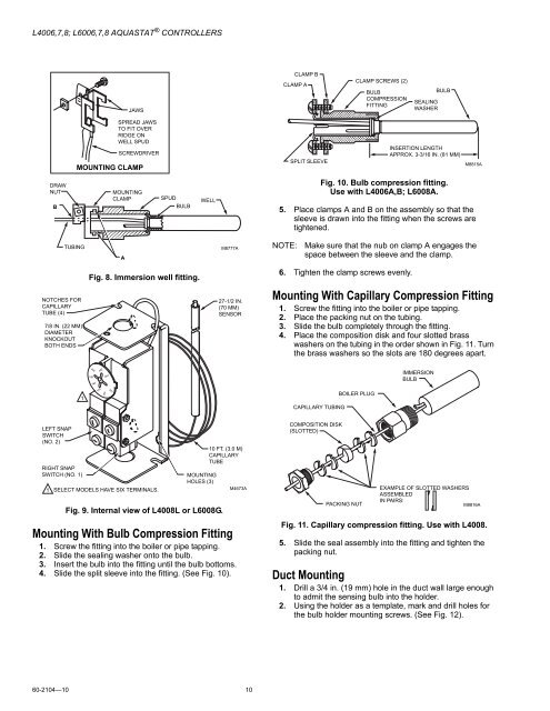
Fig. <strong>10</strong>. Bulb <strong>com</strong>pression fitting.<br />
Use with <strong>L4006</strong>A,B; L<strong>60</strong>08A.<br />
5. Place clamps A and B on the assembly so that the<br />
sleeve is drawn into the fitting when the screws are<br />
tightened.<br />
TUBING<br />
A<br />
M8777A<br />
NOTE:<br />
Make sure that the nub on clamp A engages the<br />
space between the sleeve and the clamp.<br />
Fig. 8. Immersion well fitting.<br />
6. Tighten the clamp screws evenly.<br />
NOTCHES FOR<br />
CAPILLARY<br />
TUBE (4)<br />
7/8 IN. (22 MM)<br />
DIAMETER<br />
KNOCKOUT<br />
BOTH ENDS<br />
27-1/2 IN.<br />
(70 MM)<br />
SENSOR<br />
Mounting With Capillary Compression Fitting<br />
1. Screw the fitting into the boiler or pipe tapping.<br />
2. Place the packing nut on the tubing.<br />
3. Slide the bulb <strong>com</strong>pletely through the fitting.<br />
4. Place the <strong>com</strong>position disk and four slotted brass<br />
washers on the tubing in the order shown in Fig. 11. Turn<br />
the brass washers so the slots are 180 degrees apart.<br />
180<br />
200<br />
1<strong>60</strong><br />
220<br />
240<br />
IMMERSION<br />
BULB<br />
1<br />
140<br />
120<br />
<strong>10</strong>0<br />
CAPILLARY TUBING<br />
BOILER PLUG<br />
LEFT SNAP<br />
SWITCH<br />
(NO. 2)<br />
RIGHT SNAP<br />
SWITCH (NO. 1)<br />
1 SELECT MODELS HAVE SIX TERMINALS.<br />
MOUNTING<br />
HOLES (3)<br />
Fig. 9. Internal view of L4008L or L<strong>60</strong>08G.<br />
<strong>10</strong> FT. (3.0 M)<br />
CAPILLARY<br />
TUBE<br />
Mounting With Bulb Compression Fitting<br />
1. Screw the fitting into the boiler or pipe tapping.<br />
2. Slide the sealing washer onto the bulb.<br />
3. Insert the bulb into the fitting until the bulb bottoms.<br />
4. Slide the split sleeve into the fitting. (See Fig. <strong>10</strong>).<br />
M4673A<br />
COMPOSITION DISK<br />
(SLOTTED)<br />
PACKING NUT<br />
EXAMPLE OF SLOTTED WASHERS<br />
ASSEMBLED<br />
IN PAIRS:<br />
M8816A<br />
Fig. 11. Capillary <strong>com</strong>pression fitting. Use with L4008.<br />
5. Slide the seal assembly into the fitting and tighten the<br />
packing nut.<br />
Duct Mounting<br />
1. Drill a 3/4 in. (19 mm) hole in the duct wall large enough<br />
to admit the sensing bulb into the holder.<br />
2. Using the holder as a template, mark and drill holes for<br />
the bulb holder mounting screws. (See Fig. 12).<br />
<strong>60</strong>-<strong>2<strong>10</strong>4</strong>—<strong>10</strong> <strong>10</strong>


