

60-2104-10 - L4006,7,8; L6006,7,8 Aquastat ... - PexSupply.com
60-2104-10 - L4006,7,8; L6006,7,8 Aquastat ... - PexSupply.com
60-2104-10 - L4006,7,8; L6006,7,8 Aquastat ... - PexSupply.com

You also want an ePaper? Increase the reach of your titles
YUMPU automatically turns print PDFs into web optimized ePapers that Google loves.
<strong>L4006</strong>,7,8; L<strong>60</strong>06,7,8 AQUASTAT ® CONTROLLERS<br />
L<strong>60</strong>06<br />
CIRCULATOR<br />
AND<br />
LOW LIMIT<br />
CONTROL<br />
R<br />
W<br />
B<br />
1<br />
L1<br />
(HOT)<br />
L1<br />
3<br />
B<br />
R<br />
L2<br />
L2<br />
2<br />
L8148A<br />
T<br />
T<br />
SERIES 80<br />
THERMOSTAT<br />
MILLIVOLTAGE<br />
THERMOSTAT<br />
SAFETY<br />
SHUTOFF<br />
PILOTSTAT¨<br />
POWER UNIT<br />
<strong>L4006</strong><br />
HIGH LIMIT<br />
CONTROLLER<br />
MILLIVOLTAGE<br />
VALVE OPERATOR<br />
OPERATOR<br />
COIL<br />
POWER UNIT COIL<br />
PILOT<br />
BURNER<br />
M1156A<br />
C1 C2 B1 B2<br />
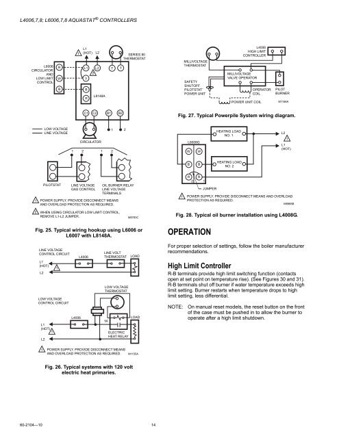
Fig. 27. Typical Powerpile System wiring diagram.<br />
LOW VOLTAGE<br />
LINE VOLTAGE<br />
1 2<br />
CIRCULATOR<br />
1<br />
1<br />
2<br />
2<br />
L<strong>60</strong>08G<br />
W<br />
W<br />
HEATING LOAD<br />
NO. 1<br />
L2<br />
1<br />
L1<br />
(HOT)<br />
B<br />
B<br />
HEATING LOAD<br />
NO. 2<br />
1<br />
PILOTSTAT<br />
LINE VOLTAGE<br />
GAS CONTROL<br />
OIL BURNER RELAY<br />
LINE VOLTAGE<br />
TERMINALS<br />
POWER SUPPLY. PROVIDE DISCONNECT MEANS<br />
AND OVERLOAD PROTECTION AS REQUIRED.<br />
R R<br />
2 1<br />
JUMPER<br />
1 POWER SUPPLY. PROVIDE DISCONNECT MEANS AND OVERLOAD<br />
PROTECTION AS REQUIRED.<br />
M8968B<br />
2<br />
WHEN USING CIRCULATOR LOW LIMIT CONTROL,<br />
REMOVE L1-L2 JUMPER.<br />
M8783C<br />
Fig. 28. Typical oil burner installation using L4008G.<br />
Fig. 25. Typical wiring hookup using L<strong>60</strong>06 or<br />
L<strong>60</strong>07 with L8148A.<br />
OPERATION<br />
LINE VOLTAGE<br />
CONTROL CIRCUIT<br />
L1<br />
(HOT)<br />
L2<br />
L1<br />
(HOT)<br />
1<br />
L2<br />
1<br />
LOW VOLTAGE<br />
CONTROL CIRCUIT<br />
<strong>L4006</strong><br />
<strong>L4006</strong><br />
LINE VOLT<br />
THERMOSTAT<br />
LOW VOLTAGE<br />
THERMOSTAT<br />
1K<br />
ELECTRIC<br />
HEAT RELAY<br />
LOAD<br />
LOAD<br />
For proper selection of settings, follow the boiler manufacturer<br />
re<strong>com</strong>mendations.<br />
High Limit Controller<br />
R-B terminals provide high limit switching function (contacts<br />
open at set point on temperature rise). (See Figures 30 and 31).<br />
R-B terminals shut off burner if water temperature exceeds high<br />
limit setting. Burner restarts when temperature drops to high<br />
limit setting, less differential.<br />
NOTE:<br />
On manual reset models, the reset button on the front<br />
of the case must be pushed in to allow the burner to<br />
operate after a high limit shutdown.<br />
1 POWER SUPPLY. PROVIDE DISCONNECT MEANS<br />
AND OVERLOAD PROTECTION AS REQUIRED.<br />
M1155A<br />
Fig. 26. Typical systems with 120 volt<br />
electric heat primaries.<br />
<strong>60</strong>-<strong>2<strong>10</strong>4</strong>—<strong>10</strong> 14


