

60-2104-10 - L4006,7,8; L6006,7,8 Aquastat ... - PexSupply.com
60-2104-10 - L4006,7,8; L6006,7,8 Aquastat ... - PexSupply.com
60-2104-10 - L4006,7,8; L6006,7,8 Aquastat ... - PexSupply.com

Create successful ePaper yourself
Turn your PDF publications into a flip-book with our unique Google optimized e-Paper software.
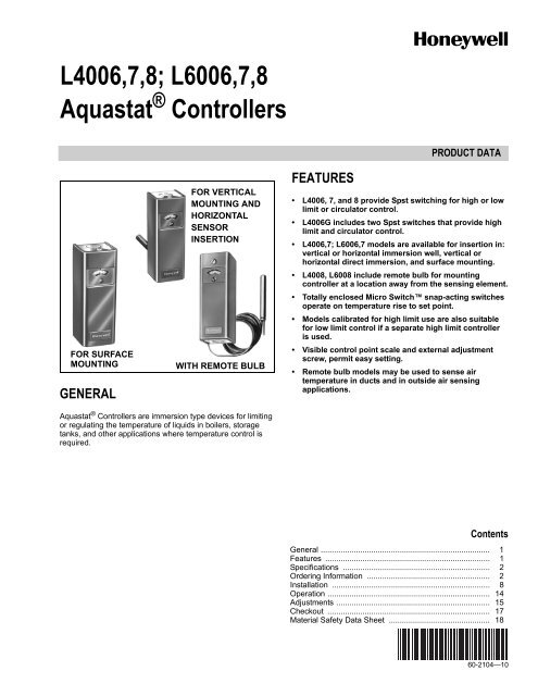
<strong>L4006</strong>,7,8; L<strong>60</strong>06,7,8<br />
<strong>Aquastat</strong> ® Controllers<br />
FOR SURFACE<br />
MOUNTING<br />
GENERAL<br />
FOR VERTICAL<br />
MOUNTING AND<br />
HORIZONTAL<br />
SENSOR<br />
INSERTION<br />
WITH REMOTE BULB<br />
FEATURES<br />
PRODUCT DATA<br />
• <strong>L4006</strong>, 7, and 8 provide Spst switching for high or low<br />
limit or circulator control.<br />
• <strong>L4006</strong>G includes two Spst switches that provide high<br />
limit and circulator control.<br />
• <strong>L4006</strong>,7; L<strong>60</strong>06,7 models are available for insertion in:<br />
vertical or horizontal immersion well, vertical or<br />
horizontal direct immersion, and surface mounting.<br />
• L4008, L<strong>60</strong>08 include remote bulb for mounting<br />
controller at a location away from the sensing element.<br />
• Totally enclosed Micro Switch snap-acting switches<br />
operate on temperature rise to set point.<br />
• Models calibrated for high limit use are also suitable<br />
for low limit control if a separate high limit controller<br />
is used.<br />
• Visible control point scale and external adjustment<br />
screw, permit easy setting.<br />
• Remote bulb models may be used to sense air<br />
temperature in ducts and in outside air sensing<br />
applications.<br />
<strong>Aquastat</strong> ® Controllers are immersion type devices for limiting<br />
or regulating the temperature of liquids in boilers, storage<br />
tanks, and other applications where temperature control is<br />
required.<br />
Contents<br />
General ............................................................................. 1<br />
Features ........................................................................... 1<br />
Specifications ................................................................... 2<br />
Ordering Information ........................................................ 2<br />
Installation ........................................................................ 8<br />
Operation .......................................................................... 14<br />
Adjustments ...................................................................... 15<br />
Checkout .......................................................................... 17<br />
Material Safety Data Sheet .............................................. 18<br />
<strong>60</strong>-<strong>2<strong>10</strong>4</strong>—<strong>10</strong>
<strong>L4006</strong>,7,8; L<strong>60</strong>06,7,8 AQUASTAT ® CONTROLLERS<br />
SPECIFICATIONS<br />
IMPORTANT<br />
The specifications given in this publication do not<br />
include normal manufacturing tolerances. Therefore,<br />
this unit may not exactly match the listed<br />
specifications. Also, this product is tested and<br />
calibrated under closely controlled conditions, and<br />
some minor differences in performance can be<br />
expected if those conditions are changed.<br />
SUPER TRADELINE ® /TRADELINE MODELS<br />
SUPER TRADELINE controls offer features not available on<br />
TRADELINE or standard models, and are designed to replace<br />
a wide range of Honeywell and <strong>com</strong>petitive controls.<br />
TRADELINE models are selected and packaged to provide<br />
ease of stocking, ease of handling, and maximum<br />
replacement value. Specifications of SUPER TRADELINE<br />
and TRADELINE controls are the same as those of standard<br />
models except as noted below.<br />
SUPER TRADELINE Model: L<strong>60</strong>06A <strong>Aquastat</strong> Controller.<br />
SUPER TRADELINE Features:<br />
SUPER TRADELINE package with cross reference label and<br />
special instructions.<br />
Factory-set stop at 240° F (116° C).<br />
Vertical or horizontal mount.<br />
Tube of heat-conductive <strong>com</strong>pound.<br />
Insulation: 1-1/2 in. to 3 in. (38 mm to 76 mm).<br />
TRADELINE Models: <strong>L4006</strong>A,B,E; L4008E; L<strong>60</strong>06C;<br />
L<strong>60</strong>08A <strong>Aquastat</strong> Controllers.<br />
TRADELINE Features Available:<br />
TRADELINE package with cross reference label and special<br />
instructions.<br />
Some TRADELINE models include immersion well.<br />
Factory-set stops at 180° F, 240° F, or 250° F (82° C, 116° C,<br />
or 121° C).<br />
Vertical or horizontal mount.<br />
Tube of heat-conductive <strong>com</strong>pound.<br />
Insulation depths of 1-1/2 in. or 3 in. (38 or 76 mm).<br />
NOTE:<br />
The following specifications are standard. Variances,<br />
available as options, are listed in Tables 1 and 2.<br />
Electrical Ratings (A):<br />
Models with 2° F (1° C) fixed differential:<br />
120 Vac 240 Vac<br />
Full Load 2.6 1.3<br />
Locked Rotor 15.6 7.8<br />
Models with 5° F (3° C) fixed differential or 5° F to 30° F<br />
(3° C to 17° C) adjustable differential:<br />
a L<strong>60</strong>08G only.<br />
Switching:<br />
<strong>L4006</strong>, L4007, L4008: Spst.<br />
L<strong>60</strong>06, L<strong>60</strong>07, L<strong>60</strong>08: Spdt (breaks R-B and makes R-W on<br />
temperature rise at setpoint).<br />
Pressure Rating:<br />
Capillary Bulb (Direct Immersion): 200 psi (1379 kPa).<br />
Immersion Well: 255 psi (1758 kPa).<br />
Sensing Bulb Material: Copper.<br />
Sensing Bulb Fill: Liquid—toluene or silicone oil.<br />
Sensing Bulb Dimensions: 2-7/8 in. (73 mm) long,<br />
3/8 in. (<strong>10</strong> mm) diameter.<br />
Wiring: Screw terminals.<br />
1<strong>10</strong>/120 Vac 200/240 Vac 277 Vac a<br />
Full Load 8.0 5.1 4.2<br />
Locked Rotor 48.0 30.6 25.2<br />
Millivoltage 0.25 at 0.25 to 12 Vdc<br />
Maximum Ambient Temperature: 150° F (66° C).<br />
ORDERING INFORMATION<br />
When purchasing replacement and modernization products from your TRADELINE ® wholesaler or distributor, refer to the<br />
TRADELINE ® Catalog or price sheets for <strong>com</strong>plete ordering number.<br />
If you have additional questions, need further information, or would like to <strong>com</strong>ment on our products or services, please write or<br />
phone:<br />
1. Your local Honeywell Automation and Control Products Sales Office (check white pages of your phone directory).<br />
2. Honeywell Customer Care<br />
1885 Douglas Drive North<br />
Minneapolis, Minnesota 55422-4386<br />
In Canada—Honeywell Limited/Honeywell Limitée, 35 Dynamic Drive, Scarborough, Ontario M1V 4Z9.<br />
International Sales and Service Offices in all principal cities of the world. Manufacturing in Australia, Canada, Finland, France,<br />
Germany, Japan, Mexico, Netherlands, Spain, Taiwan, United Kingdom, U.S.A.<br />
<strong>60</strong>-<strong>2<strong>10</strong>4</strong>—<strong>10</strong> 2
<strong>L4006</strong>,7,8; L<strong>60</strong>06,7,8 AQUASTAT ® CONTROLLERS<br />
Approvals:<br />
Underwriters Laboratories Inc:<br />
Remote bulb devices and well-mounted devices shipped<br />
without well are <strong>com</strong>ponent recognized:<br />
File No. MP466, Guide No. MBPR2.<br />
<strong>L4006</strong>A shipped with well, <strong>L4006</strong>G, L4007A,B; L<strong>60</strong>06C for<br />
surface mounting, L<strong>60</strong>06B for direct immersion mounting,<br />
and L<strong>60</strong>07A are listed: File No. MP466, Guide No. MBPR.<br />
L<strong>60</strong>08G is listed: File No. E4436, Guide No. XAPX.<br />
Canadian Standards Association: File No. LR1620,<br />
Guide No. 400-E-O.<br />
ANSI Miswiring: Models with 1/4 in. (6.35 mm) tab terminal<br />
meet ANSI Appliance Miswiring Standard.<br />
5/16<br />
(8)<br />
1 (25)<br />
KNOCKOUT FOR 3/4 (19 )<br />
CONDUIT ON ALL MODELS. SIMILAR<br />
KNOCKOUT ON BOTTOM FOR<br />
HORIZONTAL INSERTION AND<br />
REMOTE BULB MODELS.<br />
2 (51) 3/16 2-1/8 (54)<br />
(5)<br />
Mounting:<br />
Horizontal and vertical models mount directly to an immersion<br />
well installed in a boiler fitting. <strong>L4006</strong>H and L<strong>60</strong>06C contain<br />
a bracket and clamp for surface mounting on the pipe or<br />
tank. Remote bulb models have three mounting holes<br />
in rear of case for screw mounting to a vertical surface.<br />
The L<strong>60</strong>06B direct immersion model also mounts directly to<br />
a boiler fitting.<br />
Finish: Gray.<br />
Dimensions:<br />
Installation: (See Figures 1, 2, and 3).<br />
Immersion Well: (See Fig. 4).<br />
Boiler Fitting and Bulb: (See Fig. 5).<br />
Accessories and Parts:<br />
137536A Scale Lock Assembly: Includes one 137536-767<br />
Scale Lock and one 80844C-767 Screw, No. 3-48 x 3/16<br />
(5 mm).<br />
Q615A<strong>10</strong>04 Weatherproof Enclosure (for remote bulb devices<br />
only).<br />
<strong>10</strong>7408 Heat-Conductive Compound (4-oz. can).<br />
<strong>10</strong>4488 Spring Clip (stainless steel).<br />
124904 Well Adapter.<br />
Immersion Well Assemblies and Compression Fittings:<br />
See form no. 68-0040, Wells and Fittings for Temperature<br />
Controllers, for list and ordering information.<br />
5-5/8<br />
(136)<br />
1-7/8<br />
(48)<br />
KNOCKOUT FOR 3/4 (19)<br />
CONDUIT ON VERTICAL<br />
INSERTION MODELS ONLY<br />
3/4<br />
(19)<br />
RESET<br />
BUTTON<br />
(<strong>L4006</strong>E,<br />
L4008E<br />
ONLY)<br />
ELEMENT<br />
FOR VERTICAL<br />
IMMERSION<br />
11/16<br />
(18)<br />
ELEMENT FOR HORIZONTAL IMMERSION<br />
M8957A<br />
Fig. 1. Approximate case installation dimensions<br />
in inches (mm) for direct insertion models.<br />
ALTERNATE POSITION<br />
OF SENSING ELEMENT<br />
CAPILLARY<br />
3/4<br />
(19)<br />
4-3/16<br />
(<strong>10</strong>6)<br />
13/64<br />
(5) (3)<br />
MOUNTING<br />
HOLE FOR<br />
3/16 IN. (5 MM)<br />
SCREW (3)<br />
15/16<br />
(24)<br />
3/8 (<strong>10</strong>) 1-1/4<br />
(32)<br />
SENSING<br />
ELEMENT<br />
CAPILLARY<br />
ALTERNATE POSITION<br />
OF SENSING ELEMENT<br />
CAPILLARY M8823<br />
Fig. 2. Approximate installation dimensions<br />
in inches (mm) for remote bulb models. Other<br />
dimensions are the same as Fig. 1.<br />
3 <strong>60</strong>-<strong>2<strong>10</strong>4</strong>—<strong>10</strong>
<strong>L4006</strong>,7,8; L<strong>60</strong>06,7,8 AQUASTAT ® CONTROLLERS<br />
7/8 IN. (22 MM)<br />
STANDARD<br />
KNOCKOUT (2)<br />
1/2 — 14 IN. NPT<br />
7/16<br />
(11)<br />
C L<br />
1<br />
(25)<br />
1-1/2 (38) 3 (76)<br />
M8789A<br />
Fig. 4. Approximate immersion well dimensions in inches<br />
(mm) for all models except <strong>L4006</strong>C and L<strong>60</strong>06B.<br />
1/2 OR 3/4 — 14 IN. NPT<br />
3/8<br />
(<strong>10</strong>)<br />
5-5/8<br />
(136)<br />
1-5/16 (33) 3 (76)<br />
M8799A<br />
Fig. 5. Approximate boiler fitting and bulb dimensions<br />
in inches (mm) for <strong>L4006</strong>C and L<strong>60</strong>06B.<br />
2 (51)<br />
2-3/4 (70)<br />
2 (51)<br />
M8958A<br />
Fig. 3. Approximate installation dimensions<br />
in inches (mm) for surface mount models.<br />
<strong>60</strong>-<strong>2<strong>10</strong>4</strong>—<strong>10</strong> 4
<strong>L4006</strong>,7,8; L<strong>60</strong>06,7,8 AQUASTAT ® CONTROLLERS<br />
Standard Models:<br />
<strong>L4006</strong>,A,B,C,E,G; L4007,A,B; L4008A,B.E; L<strong>60</strong>06A,B,C; L<strong>60</strong>07A, L<strong>60</strong>08,A,G,H<br />
Model<br />
<strong>L4006</strong>A<br />
Application<br />
High or low<br />
limit<br />
Table 1. <strong>L4006</strong>, L4007, L4008 Controller (SPST Switching) Specifications.<br />
Range<br />
°F (°C)<br />
40° F to 180° F<br />
(4° C to 82° C)<br />
or<br />
<strong>10</strong>0° F to 240° F<br />
(38° C to 116° C)<br />
<strong>L4006</strong>B Circulator <strong>10</strong>0° F to 240° F<br />
(38° C to 116° C)<br />
<strong>L4006</strong>C<br />
High or low<br />
limit<br />
65° F to 200° F<br />
(18° C to 93° C)<br />
<strong>L4006</strong>E b High limit 130° F to 290° F<br />
(54° C to 141° C)<br />
Midscale<br />
Switching On<br />
°F (°C) Insertion a Rise<br />
Differential<br />
Temperature<br />
2° F or 5° F fixed<br />
(1° C or 3° C)<br />
or<br />
5° F to 30° F<br />
adjustable<br />
(3° C to 17° C)<br />
5° F (3° C) fixed<br />
or 5° F to 30° F<br />
(3° C to 17° C)<br />
adjustable<br />
3-1/2° F (2° C)<br />
fixed<br />
Manual reset<br />
Available Options<br />
Horizontal Breaks — TRADELINE models<br />
available.<br />
— NPT brass spud 1/2 in. or<br />
3/4 in.<br />
(13 mm to 19 mm)<br />
— Special capillary assembly.<br />
— Insertion 3-3/8 in. or<br />
5 in. (86 or 127 mm)<br />
— Celsius scale markings.<br />
— Factory-set stops at 1<strong>60</strong>°,<br />
180°, 185°, 200°, 220°, or<br />
230° F (71°, 82°, 85°, 93°,<br />
<strong>10</strong>4°, or 1<strong>10</strong>° C).<br />
— Insulation depths of<br />
1-1/2 in. , 3 in. or 4 in.<br />
(38 mm, 76 mm, or<br />
<strong>10</strong>2 mm).<br />
— Screw and mounting<br />
brackets.<br />
— Plastic tubing over well.<br />
— Modified dial with stop.<br />
— Special cover and knobs.<br />
— With ground screw.<br />
Horizontal Makes — TRADELINE model<br />
available.<br />
— Insulation depth 1-1/2 in. or<br />
3 in.<br />
(38 mm or 76 mm).<br />
— NPT brass spud 3/4 in.<br />
(19 mm)<br />
— Screw in front of case on<br />
dial suitable for<br />
Powerpile ® control.<br />
— Factory-set stop at<br />
240° F (116° C).<br />
Horizontal<br />
direct<br />
immersion<br />
Horizontal or<br />
vertical<br />
Breaks — TRADELINE model<br />
available.<br />
— Less cover.<br />
— Capillary <strong>10</strong> in.<br />
(254 mm).<br />
— NPT brass spud 3/4 in.<br />
(19 mm).<br />
Breaks — TRADELINE model<br />
available.<br />
— Insulation depth<br />
1-1/2 in. or 3 in.<br />
(38 or 76 mm).<br />
— NPT brass spud 1/2 in. (13<br />
mm)<br />
— Factory-set stop at<br />
250° F (121° C).<br />
— Capillary 8 in. (203 mm).<br />
a Some models include copper well or fitting; specify when ordering. Also specify boiler tapping size 1/2 or 3/4 in.<br />
(13 to 19 mm) NPT and insulation depth.<br />
b Manual reset (trip-free) switch breaks circuit and locks out when controlled medium reaches setpoint. Controlled temperature<br />
must drop 20° F (11° C) below setpoint before contacts can be manually reset.<br />
5 <strong>60</strong>-<strong>2<strong>10</strong>4</strong>—<strong>10</strong>
<strong>L4006</strong>,7,8; L<strong>60</strong>06,7,8 AQUASTAT ® CONTROLLERS<br />
Model<br />
<strong>L4006</strong>G<br />
L4007A<br />
High limit<br />
and<br />
circulator<br />
control<br />
High or low<br />
limit<br />
<strong>10</strong>0° F to 200° F<br />
(38° C to 93° C)<br />
<strong>10</strong>0° F to 240° F<br />
(38° C to 116° C)<br />
L4007B Circulator <strong>10</strong>0° F to 240° F<br />
(38° C to 116° C)<br />
L4008A<br />
Application<br />
High or low<br />
limit<br />
Table 1. <strong>L4006</strong>, L4007, L4008 Controller (SPST Switching) Specifications. (Cont.)<br />
Range<br />
°F (°C)<br />
<strong>10</strong>0° F to 240° F<br />
(38° C to 116° C)<br />
or<br />
130° F to 270° F<br />
(54° C to 132° C)<br />
L4008B Circulator <strong>10</strong>0° F to 240° F<br />
(38° C to 116° C)<br />
L4008E b High limit 40° F to 80° F<br />
(4° C to 27° C) or<br />
130° F to 270° F<br />
(54° C to 132° C)<br />
Midscale<br />
Switching On<br />
°F (°C) Insertion a Rise<br />
Differential<br />
Temperature<br />
<strong>10</strong>° F (6° C) fixed Horizontal Two switches<br />
break<br />
simultaneously<br />
2° F or 5° F<br />
(1° C or 3° C)<br />
fixed,<br />
5° F to 30° F<br />
(3° C to 17° C)<br />
adjustable<br />
5° F (3° C) fixed<br />
or<br />
5° F to 30° F<br />
(3° C to 17° C)<br />
adjustable<br />
5° F (3° C) fixed,<br />
5° F to 30° F<br />
(3° C to 17° C)<br />
adjustable<br />
5° F (3° C) fixed<br />
or<br />
5° F to 30° F<br />
(3° C to 17° C)<br />
adjustable<br />
Horizontal or<br />
vertical<br />
— External adjustment knob.<br />
— Insulation depth 4 in.<br />
(<strong>10</strong>2 mm).<br />
— Factory-set stop at<br />
1<strong>60</strong>° F (71° C).<br />
— Celsius scale markings.<br />
— Without well.<br />
Breaks — Insulation depth<br />
1-1/2 in. or 3 in.<br />
(38 mm or 76 mm).<br />
Vertical Makes — Celsius scale markings.<br />
Remote bulb<br />
direct<br />
immersion<br />
Remote bulb<br />
direct<br />
immersion<br />
Available Options<br />
Breaks — Remote capillary<br />
5-1/2 ft (1.7 m),<br />
8-1/2 ft (2.6 m) or<br />
<strong>10</strong> ft (3.0 m).<br />
— Factory-set scale stops at<br />
120°, 170°, or 200° F (49°,<br />
77°, or 93° C)<br />
— Celsius scale markings.<br />
— Front cover screw.<br />
Makes — Capillary 5-1/2 ft<br />
(1.7 m).<br />
Manual reset Remote bulb Breaks — Factory-set scale stops at<br />
140°, 200°, or 250° F (<strong>60</strong>°,<br />
93°, or 121° C).<br />
— Capillary 5-1/2 ft or<br />
20 ft (1.7m or 6.1 m).<br />
a<br />
Some models include copper well or fitting; specify when ordering. Also specify boiler tapping size 1/2 or 3/4 in.<br />
(13 to 19 mm) NPT and insulation depth.<br />
b Manual reset (trip-free) switch breaks circuit and locks out when controlled medium reaches setpoint. Controlled temperature<br />
must drop 20° F (11° C) below setpoint before contacts can be manually reset.<br />
<strong>60</strong>-<strong>2<strong>10</strong>4</strong>—<strong>10</strong> 6
<strong>L4006</strong>,7,8; L<strong>60</strong>06,7,8 AQUASTAT ® CONTROLLERS<br />
Model<br />
L<strong>60</strong>06A<br />
L<strong>60</strong>06B<br />
L<strong>60</strong>06C<br />
L<strong>60</strong>07A<br />
L<strong>60</strong>08A<br />
L<strong>60</strong>08G<br />
L<strong>60</strong>08H<br />
(maximum<br />
temperature<br />
of element<br />
405° F<br />
(207° C))<br />
Application<br />
Circulator and low<br />
limit or high limit<br />
Circulator and low<br />
limit or high limit<br />
Circulator, low limit,<br />
and high limit<br />
Circulator and low<br />
limit or high limit<br />
Circulator and low<br />
limit cooling<br />
Two-stage <strong>Aquastat</strong><br />
Controller to cycle<br />
two-stage gas<br />
valve.<br />
Low fire <strong>Aquastat</strong><br />
Controller<br />
Table 2. L<strong>60</strong>06, L<strong>60</strong>07, L<strong>60</strong>08 Controller (SPDT Switching) Specifications.<br />
Range<br />
°F (°C)<br />
<strong>10</strong>0° F to 240° F<br />
(38° C to 116° C)<br />
or<br />
<strong>10</strong>0° F to 290° F<br />
(38° C to 143° C)<br />
<strong>10</strong>0° F to 240° F<br />
(38° C to 116° C)<br />
65° F to 200° F<br />
(18° C to 93° C)<br />
40° F to 180° F<br />
(4° C to 82° C)<br />
<strong>10</strong>0° F to 240° F<br />
(38° C to 116° C)<br />
or<br />
-30° F to +70° F<br />
(-35° C to +21° C)<br />
130° F to 230° F<br />
(54° C to 1<strong>10</strong>° C) or<br />
<strong>60</strong>° F to 1<strong>60</strong>° F (16°<br />
C to 71° C)<br />
150° F to 200° F<br />
(66° C to 93° C)<br />
Midscale<br />
Differential<br />
°F (°C) Insertion a Available Options<br />
5° F (3° C) fixed<br />
or<br />
5° F to 30° F<br />
(3° C to 17° C)<br />
adjustable<br />
5° F (3° C) fixed<br />
or<br />
5° F to 30° F<br />
(3° C to 17° C)<br />
adjustable, or<br />
30° F (17° C)<br />
fixed.<br />
5° F (3° C) fixed<br />
or<br />
5° F to 30° F<br />
(3° C to 17° C)<br />
adjustable<br />
Fixed<br />
5° F (3° C) fixed<br />
or<br />
5° F to 30° F<br />
(3° C to 17° C)<br />
adjustable<br />
3-1/2° F (2° C)<br />
fixed<br />
15° F (8° C)<br />
fixed<br />
Horizontal — SUPER TRADELINE model<br />
available.<br />
— Modified dial with stop.<br />
— NPT brass spud 1/2 in. or 3/4<br />
in. (13 mm to 19 mm)<br />
— 3-3/8 in. (86 mm) insertion.<br />
— Without well.<br />
— Adapter for horizontal or<br />
vertical mount.<br />
— Insulation depth 1-1/2 in. or<br />
3 in. (38 mm or 76 mm).<br />
Horizontal — Direct immersion.<br />
— Insulation depth 1-1/2 in.<br />
(38 mm).<br />
— 3/4 in. (19 mm ) brass<br />
<strong>com</strong>pression fitting.<br />
Horizontal or<br />
vertical surface<br />
mounted<br />
Horizontal or<br />
vertical<br />
— TRADELINE model available.<br />
— Strap-on, surface mount.<br />
— Insulation depth 1-1/2 in. or 3<br />
in. (38 mm or 76 mm).<br />
Remote bulb — TRADELINE models<br />
available.<br />
— Modified dial with stop.<br />
— Capillary 5-1/2 ft (1.7 m).<br />
Remote bulb — Capillary 6 ft (1.8 m).<br />
— Adjustable interstage<br />
differential; 5° F to <strong>10</strong>° F<br />
(2° C to 6° C).<br />
Remote bulb — Capillary 33 in. (0.8 m).<br />
a Some models include copper well or fitting; specify when ordering. Also specify boiler tapping size 1/2 or 3/4 in. NPT and<br />
insulation depth.<br />
7 <strong>60</strong>-<strong>2<strong>10</strong>4</strong>—<strong>10</strong>
<strong>L4006</strong>,7,8; L<strong>60</strong>06,7,8 AQUASTAT ® CONTROLLERS<br />
INSTALLATION<br />
When Installing This Product…<br />
1. Read these instructions carefully. Failure to follow them<br />
could damage the product or cause a hazardous<br />
condition.<br />
2. Check the ratings given in the instructions and on the<br />
product to make sure the product is suitable for your<br />
application.<br />
3. Installer must be a trained, experienced service<br />
technician.<br />
4. After installation is <strong>com</strong>plete, check product operation as<br />
provided in these instructions.<br />
WARNING<br />
Explosion Hazard.<br />
Can cause serious injury, death or property<br />
damage.<br />
This product is intended for use only in systems with a<br />
pressure relief valve.<br />
WARNING<br />
Electrical Shock Hazard.<br />
Can cause serious injury or death.<br />
Disconnect power supply before beginning installation<br />
to prevent electrical shock or equipment damage.<br />
CAUTION<br />
Equipment Damage Hazard.<br />
Use of incorrect device or improper installation can<br />
damage the system.<br />
1. Do not replace immersion-type <strong>Aquastat</strong> Controller<br />
with strap-on <strong>Aquastat</strong> Controller.<br />
2. Do not secure draw nut so tightly that retainer clamp<br />
can collapse tubing.<br />
IMPORTANT<br />
1. Terminals on these <strong>Aquastat</strong> relays are approved for<br />
copper wire only.<br />
2. Controller may be used with or without immersion<br />
well. If used, well must snugly fit sensing bulb for best<br />
thermal response. Insert bulb until it rests against the<br />
bottom of the well. Use well of correct length and<br />
bend the tubing, if necessary, to provide enough force<br />
to hold the bulb against the bottom of the well. Avoid<br />
making a sharp bend in the tubing as it can produce a<br />
break in the tubing and cause loss of fill. This<br />
condition causes the High and Low Limit controls to<br />
be made continuously.<br />
3. If well does not snugly fit on bulb, use the heatconductive<br />
<strong>com</strong>pound, included with Super Tradeline<br />
and Tradeline models, as follows: Fold the plastic bag<br />
of <strong>com</strong>pound lengthwise and twist gently. Snip the<br />
end of the bag and insert into the well. Slowly pull out<br />
the bag while squeezing firmly to distribute <strong>com</strong>pound<br />
evenly in the well. Insert the bulb into the well. Bend<br />
the tubing, if necessary, to provide force to hold the<br />
bulb against the bottom of the well and to hold the<br />
outer end of the bulb firmly in contact with the side of<br />
the well. Wipe off excess <strong>com</strong>pound.<br />
The manufacturer usually provides a tapping for insertion of<br />
the controller sensing element. This tapping is located at a<br />
point where typical water temperature can be measured.<br />
Depending on the model, the element is inserted in an<br />
immersion well, through a boiler fitting, or directly immersed.<br />
Installation should be made by a qualified service technician.<br />
Follow the instructions furnished by the system manufacturer, if<br />
available. Otherwise, refer to appropriate procedure listed<br />
below.<br />
Mounting Immersion Well and Direct<br />
Immersion Models (<strong>L4006</strong>A,B,C,E,G;<br />
L4007A,B; L<strong>60</strong>06A,B; L<strong>60</strong>07A)<br />
Installing Immersion Well Models<br />
(<strong>L4006</strong>A,B,E,G; L4007A,B; L<strong>60</strong>06A; L<strong>60</strong>07A)<br />
On an existing installation, shut off the power and remove the<br />
old control. If the old immersion well appears suitable, and if<br />
the adapter clamp on the <strong>Aquastat</strong> Controller fits the old well<br />
spud, this well does not need to be replaced.<br />
To replace the well:<br />
1. If the system is filled, drain the system to a point below<br />
the boiler tapping.<br />
2. Remove the old well from the boiler tapping.<br />
3. Install the immersion well included with the controller. If<br />
the boiler tapping is greater than 1/2 in. (13 mm), use a<br />
reduction fitting to adapt the boiler opening to the 1/2 in.<br />
(13 mm) threads that are standard with the well or fitting.<br />
Fittings with 3/4 in. (19 mm) threads are also available.<br />
4. Fill the system. Make sure that the well is screwed in<br />
tightly enough to prevent leakage. Do not use the case<br />
as a handle to tighten the well after the controller is<br />
secured to the well.<br />
To install the controller:<br />
1. Loosen the screw (at the top of the case, above the<br />
scale setting), and remove the cover. Loosen the two<br />
screws that secure the adapter clamp. (See Fig. 6).<br />
2. Insert the sensing element into the immersion well.<br />
3. Fasten the case of the <strong>Aquastat</strong> Controller to the well<br />
with the adapter clamp. Make certain that the clamp is<br />
properly positioned over the groove of the well spud.<br />
Also, be sure the flange at the opening of the well fits<br />
snugly into the opening of the case. The sensing bulb<br />
must bottom in the well.<br />
NOTE:<br />
Some models include up to 3 in. (76 mm) extra capillary<br />
tubing inside the case. In these models, pull out<br />
the extra tubing, if needed.<br />
<strong>60</strong>-<strong>2<strong>10</strong>4</strong>—<strong>10</strong> 8
<strong>L4006</strong>,7,8; L<strong>60</strong>06,7,8 AQUASTAT ® CONTROLLERS<br />
M8806A<br />
2<br />
Fig. 6. Internal view of L<strong>60</strong>06A.<br />
Installing Direct Immersion Models<br />
(<strong>L4006</strong>C, L<strong>60</strong>06B)<br />
Models that provide for direct immersion of the sensing<br />
element into the boiler include a bulb <strong>com</strong>pression fitting<br />
assembly instead of an immersion well. Install the fitting in the<br />
boiler tapping as follows:<br />
1. Be sure the sealing washer is in place as shown in<br />
Fig. 7. Make sure that the spud of the bulb <strong>com</strong>pression<br />
fitting is screwed in tightly enough to prevent leaking.<br />
ADAPTER<br />
CLAMP<br />
SETPOINT<br />
INDICATING DIAL<br />
DIFFERENTIAL<br />
ADJUSTMENT<br />
WHEEL<br />
ADAPTER CLAMP<br />
SCREWS<br />
INSERTION<br />
ELEMENT<br />
1<br />
2<br />
1<br />
WITH VERTICAL MOUNTING OF<br />
IMMERSION WELL, ELEMENT IS<br />
ATTACHED TO BOTTOM OF THE<br />
CASE.<br />
SELECT MODELS HAVE SCREW<br />
TERMINAL, NOT TAB TERMINAL.<br />
2. Insert the immersion sensing bulb through the bulb<br />
<strong>com</strong>pression fitting. Adjust the adapter clamp so that the<br />
clamp fits over the groove at the opening of the bulb<br />
<strong>com</strong>pression fitting.<br />
3. Tighten the adapter clamp screws so that the <strong>Aquastat</strong><br />
Controller is firmly attached to the bulb <strong>com</strong>pression<br />
fitting.<br />
Mounting Remote Bulb Models<br />
(L4008A,B,E; L<strong>60</strong>08A,G,H)<br />
The remote temperature-sensing bulb can either be installed in<br />
an immersion well (See Fig. 8) that extends into the boiler or<br />
tank, or it can be directly immersed in the controlled medium<br />
(See Fig. 9). For installations that do not use a well, secure the<br />
remote bulb with a bulb <strong>com</strong>pression fitting (See Fig. <strong>10</strong>), or<br />
capillary <strong>com</strong>pression fitting. (See Fig. 11).<br />
Order well, well adapter, bulb <strong>com</strong>pression fitting or capillary<br />
<strong>com</strong>pression fitting separately. See form no. 68-0040, Wells<br />
and Fittings for Temperature Controllers. If used, well must<br />
snugly fit sensing bulb for the best thermal response. Insert<br />
bulb until it rests against the bottom of the well. Hold it there<br />
while tightening the tubing clamp. (See Fig. 8).<br />
The boiler manufacturer usually provides a tapping for the<br />
insertion of the <strong>Aquastat</strong> Controller sensing element. This<br />
tapping should be located at a point where typical water<br />
temperature can be measured. Never locate the bulb or<br />
protecting immersion well close to a hot or cold water inlet or a<br />
steam coil.<br />
If the system is filled, drain system to a point below the boiler<br />
tapping, or wherever the sensing bulb is to be installed.<br />
The bulb can also be installed in the supply line of an indirect<br />
water heater, in the direct water heater itself, or in the feed<br />
riser, about 6 in. (153 mm) above the boiler. If the riser is<br />
valved, the bulb can be installed between the boiler and the<br />
valve.<br />
NOTE:<br />
Do not make sharp bends or kinks in the capillary.<br />
Make bends no sharper than 1 in. (25 mm) radius.<br />
SPLIT SLEEVE<br />
ADAPTER CLAMPS<br />
FIT OVER<br />
GROOVE<br />
SENSING BULB<br />
SEALING WASHER<br />
BULB COMPRESSION<br />
FITTING<br />
Fig. 7. Direct immersion model<br />
with fitting partially removed.<br />
M8774A<br />
After installing the controller, carefully coil the excess capillary<br />
at the bottom of the controller case.<br />
Mounting Immersion Well<br />
1. Screw the well into the boiler, tank, or pipe tapping.<br />
2. Insert the bulb in the well, pushing the tubing until the<br />
bulb bottoms in the well.<br />
3. Attach the retainer clamp to the end of the well spud.<br />
Loosen the draw nut and spread the jaws of the clamp<br />
with the screwdriver if necessary. (See Fig. 8).<br />
4. With the retainer clamp attached to the well spud (be<br />
sure the jaws of the clamp hook over the ridge at the end<br />
of the spud, as shown at points A in Fig. 8), adjust the<br />
tubing to fit through the retainer clamp groove, as shown<br />
at point B in Fig. 8.<br />
5. Tighten the draw nut so that the retainer clamp is firmly<br />
attached to the well spud and the tubing is held securely<br />
in place.<br />
9 <strong>60</strong>-<strong>2<strong>10</strong>4</strong>—<strong>10</strong>
<strong>L4006</strong>,7,8; L<strong>60</strong>06,7,8 AQUASTAT ® CONTROLLERS<br />
JAWS<br />
CLAMP B<br />
CLAMP A<br />
CLAMP SCREWS (2)<br />
BULB<br />
COMPRESSION<br />
FITTING<br />
SEALING<br />
WASHER<br />
BULB<br />
SPREAD JAWS<br />
TO FIT OVER<br />
RIDGE ON<br />
WELL SPUD<br />
SCREWDRIVER<br />
MOUNTING CLAMP<br />
SPLIT SLEEVE<br />
INSERTION LENGTH<br />
APPROX. 3-3/16 IN. (81 MM)<br />
M8815A<br />
DRAW<br />
NUT<br />
B<br />
MOUNTING<br />
CLAMP<br />
SPUD<br />
BULB<br />
WELL<br />
Fig. <strong>10</strong>. Bulb <strong>com</strong>pression fitting.<br />
Use with <strong>L4006</strong>A,B; L<strong>60</strong>08A.<br />
5. Place clamps A and B on the assembly so that the<br />
sleeve is drawn into the fitting when the screws are<br />
tightened.<br />
TUBING<br />
A<br />
M8777A<br />
NOTE:<br />
Make sure that the nub on clamp A engages the<br />
space between the sleeve and the clamp.<br />
Fig. 8. Immersion well fitting.<br />
6. Tighten the clamp screws evenly.<br />
NOTCHES FOR<br />
CAPILLARY<br />
TUBE (4)<br />
7/8 IN. (22 MM)<br />
DIAMETER<br />
KNOCKOUT<br />
BOTH ENDS<br />
27-1/2 IN.<br />
(70 MM)<br />
SENSOR<br />
Mounting With Capillary Compression Fitting<br />
1. Screw the fitting into the boiler or pipe tapping.<br />
2. Place the packing nut on the tubing.<br />
3. Slide the bulb <strong>com</strong>pletely through the fitting.<br />
4. Place the <strong>com</strong>position disk and four slotted brass<br />
washers on the tubing in the order shown in Fig. 11. Turn<br />
the brass washers so the slots are 180 degrees apart.<br />
180<br />
200<br />
1<strong>60</strong><br />
220<br />
240<br />
IMMERSION<br />
BULB<br />
1<br />
140<br />
120<br />
<strong>10</strong>0<br />
CAPILLARY TUBING<br />
BOILER PLUG<br />
LEFT SNAP<br />
SWITCH<br />
(NO. 2)<br />
RIGHT SNAP<br />
SWITCH (NO. 1)<br />
1 SELECT MODELS HAVE SIX TERMINALS.<br />
MOUNTING<br />
HOLES (3)<br />
Fig. 9. Internal view of L4008L or L<strong>60</strong>08G.<br />
<strong>10</strong> FT. (3.0 M)<br />
CAPILLARY<br />
TUBE<br />
Mounting With Bulb Compression Fitting<br />
1. Screw the fitting into the boiler or pipe tapping.<br />
2. Slide the sealing washer onto the bulb.<br />
3. Insert the bulb into the fitting until the bulb bottoms.<br />
4. Slide the split sleeve into the fitting. (See Fig. <strong>10</strong>).<br />
M4673A<br />
COMPOSITION DISK<br />
(SLOTTED)<br />
PACKING NUT<br />
EXAMPLE OF SLOTTED WASHERS<br />
ASSEMBLED<br />
IN PAIRS:<br />
M8816A<br />
Fig. 11. Capillary <strong>com</strong>pression fitting. Use with L4008.<br />
5. Slide the seal assembly into the fitting and tighten the<br />
packing nut.<br />
Duct Mounting<br />
1. Drill a 3/4 in. (19 mm) hole in the duct wall large enough<br />
to admit the sensing bulb into the holder.<br />
2. Using the holder as a template, mark and drill holes for<br />
the bulb holder mounting screws. (See Fig. 12).<br />
<strong>60</strong>-<strong>2<strong>10</strong>4</strong>—<strong>10</strong> <strong>10</strong>
<strong>L4006</strong>,7,8; L<strong>60</strong>06,7,8 AQUASTAT ® CONTROLLERS<br />
Mounting Remote Bulb Models<br />
For Outdoor Air Sensing<br />
These models have a 5 ft (1.5 m) capillary that establishes the<br />
maximum distance between the case and the outdoor<br />
mounting.<br />
Fig. 12. Bulb support.<br />
3. Break the holder to the desired length. (See Fig. 13).<br />
NOTE:<br />
M8970A<br />
The holder must be long enough to hold the sensing<br />
bulb in freely circulating air away from the duct wall.<br />
Neatly coil the excess capillary at the controller case<br />
or at the bulb holder.<br />
Install the bulb on the outside of the building in the shield<br />
provided (See Fig. 15) where it can be exposed to<br />
representative air temperature, but not to direct sunlight. Mount<br />
the bulb high enough so that accumulated snow, leaves, or<br />
other debris cannot obstruct circulation of air around it, and<br />
where children cannot reach it. Avoid vents from the building.<br />
Install the case at the indoor location selected, fastening the<br />
screws through holes in the back of the case. Bring out the<br />
bulb and tubing through a 3/4 in. (19 mm) hole in the outside<br />
wall, avoiding sharp bends or kinks. Leave excess tubing<br />
coiled near the case. Do not make sharp bends near the case<br />
or bulb.<br />
Slip the bulb through the supports in the shield. Pinch the split<br />
supporting clip until it holds the bulb firmly in position. If the<br />
seal-off tube protrudes from under the shield, bend it under as<br />
shown in Fig. 15.<br />
Fig. 13. Removing excess bulb support.<br />
M7216A<br />
Hold the shield over the mounting position and form a smallradius<br />
bend in the tubing. Place the split plug around the tubing<br />
and move the shield into the mounting location as a unit. Push<br />
the split plug into the hole until it is wedged securely in place.<br />
Fasten the shield in place on the wall with the screws provided.<br />
NOTE:<br />
If the tubing is properly shaped and the split plug<br />
installed as directed, the shield will cover the split<br />
plug, and the hole in the wall will be hidden from sight.<br />
SPLIT WOOD PLUG<br />
PINCH TOP EDGES OF<br />
HOLDER TOGETHER<br />
AT EACH SEGMENT<br />
CAPILLARY<br />
TUBING<br />
INSERT BULB<br />
IN CLAMP<br />
OUTDOOR<br />
SENSING<br />
BULB<br />
3/4 IN.<br />
(19 MM)<br />
HOLE IN<br />
WALL<br />
SENSING<br />
BULB<br />
SEAL-OFF<br />
TUBE<br />
CAPILLARY<br />
TUBING<br />
BE SURE EXTENSION TUBE IS<br />
UNDER BULB HOLDER, AS SHOWN<br />
M7217A<br />
Fig. 14. Securing capillary in bulb holder.<br />
4. Place the capillary in the bulb holder channel. Pinch the<br />
top edges of the holder together at each segment. (See<br />
Fig. 14).<br />
5. Insert the bulb holder into the controlled area through the<br />
hole prepared in step 1.<br />
6. Fasten the bulb holder to the duct wall with the screws<br />
provided.<br />
34886A<br />
BULB<br />
SHIELD<br />
M8800A<br />
Fig. 15. Mounting bulb in shield outside building.<br />
Mounting L<strong>60</strong>08A Remote Bulb Controller<br />
Mounting with Guard Bracket<br />
Mount the bulb in the guard bracket as shown in Fig. 16.<br />
Locate the bulb and bracket <strong>com</strong>bination, in freely circulating<br />
air, in the controlled area. With screws provided, fasten the<br />
bracket in place.<br />
11 <strong>60</strong>-<strong>2<strong>10</strong>4</strong>—<strong>10</strong>
<strong>L4006</strong>,7,8; L<strong>60</strong>06,7,8 AQUASTAT ® CONTROLLERS<br />
Mounting on Suction Line<br />
1. In cooling units with more than one suction line, place<br />
the sensing bulb on the <strong>com</strong>mon line.<br />
2. Make certain the bulb is at least 2 ft (0.6 m) from the<br />
point at which the suction line leaves the cooler. This<br />
prevents the outside temperature from being transmitted<br />
to the remote bulb through the copper tubing of the<br />
suction line.<br />
3. Place the remote sensing bulb on the side of the<br />
horizontal suction line between the coil and trap (not on<br />
the trap).<br />
4. Attach the sensing bulb to the suction line with clips or<br />
straps. (See Fig. 17).<br />
5. Coil the excess length of capillary tubing near the<br />
L<strong>60</strong>08A case.<br />
SUPPORTING<br />
CLIP<br />
Wiring<br />
Disconnect power supply before beginning installation to<br />
prevent electrical shock or equipment damage.<br />
All wiring must <strong>com</strong>ply with local codes and ordinances<br />
regarding wire size, type of insulation, enclosure, etc.<br />
Figures 19 through 28 show typical hookups.<br />
When wiring a switch equipped with a 1/4 in. (19 mm) tab<br />
terminal connector, use 18 AWG to 22 AWG (0.8 mm 2 to<br />
0.3 mm 2 ) gauge wire with an AMP Inc. part no. 2-520129-2<br />
fully insulated flag receptable connector or equivalent.<br />
ENCLOSED<br />
SENSING BULB<br />
PIPE<br />
SENSOR<br />
12 IN.<br />
ADJUSTABLE<br />
PIPE<br />
STRAP<br />
MOUNTING<br />
BRACKET<br />
M8791A<br />
Fig. 16. Securing remote bulb in clip<br />
when mounting with guard bracket.<br />
COOLER<br />
WALL<br />
SUCTION LINE<br />
LEAVES<br />
COOLER<br />
L<strong>60</strong>08A<br />
CIRCULATOR<br />
LOW LIMIT<br />
CONTROLLER<br />
COIL<br />
SUCTION<br />
LINE<br />
AQUASTAT ®<br />
CONTROLLER CASE<br />
M8771B<br />
Fig. 18. Mounting <strong>L4006</strong>H or L<strong>60</strong>06C directly on surface.<br />
CAPILLARY<br />
REMOTE<br />
BULB<br />
BULB CLIPS<br />
TO SUCTION LINE<br />
M8805A<br />
Fig. 17. Attaching remote bulb to horizontal suction line.<br />
Mounting Surface Mount Models<br />
The <strong>L4006</strong>H and L<strong>60</strong>06C are designed for surface mounting<br />
on piping or tanks. Mount the controller directly on the tank<br />
surface using the adjustable mounting bracket as shown in<br />
Fig. 18. The controller can be mounted in any position.<br />
When mounting the <strong>L4006</strong>H or L<strong>60</strong>06C on piping, the pipe<br />
should be 1 in. (25 mm) diameter or larger for accurate<br />
temperature sensing. Remove any insulation from the pipe.<br />
Thoroughly scrape off all scale, rust, or paint. Mount the<br />
controller using adjustable bracket provided. Turn on power.<br />
2<br />
1<br />
24 VOLT<br />
THERMOSTAT<br />
LOW WATER<br />
CUTOFF<br />
<strong>L4006</strong>A OR<br />
L4007A<br />
LOW LIMIT<br />
AQUASTAT ®<br />
CONTROLLER<br />
GAS<br />
VALVE<br />
PRESSURE<br />
CONTROL<br />
PILOTSTAT<br />
CONTROL<br />
POWER SUPPLY. PROVIDE DISCONNECT MEANS AND<br />
OVERLOAD PROTECTION AS REQUIRED.<br />
L1<br />
(HOT)<br />
L2<br />
1<br />
2 USE <strong>L4006</strong>E FOR MANUAL RESET.<br />
M2856B<br />
Fig. 19. Typical gas-fired system with domestic hot water.<br />
<strong>60</strong>-<strong>2<strong>10</strong>4</strong>—<strong>10</strong> 12
<strong>L4006</strong>,7,8; L<strong>60</strong>06,7,8 AQUASTAT ® CONTROLLERS<br />
PROTECTORELAY<br />
CONTROL<br />
1<br />
2<br />
<strong>L4006</strong>A OR L4007A HIGH<br />
LIMIT CONTROLLER<br />
L1<br />
(HOT)<br />
1<br />
L2<br />
T<br />
T<br />
24 VOLT<br />
THERMOSTAT<br />
RA832A<br />
SWITCHING RELAY<br />
2<br />
1<br />
L1 L2<br />
(HOT)<br />
<strong>L4006</strong>A OR L4007A<br />
HIGH LIMIT<br />
AQUASTAT ®<br />
CONTROLLER<br />
1<br />
24 VOLT<br />
THERMOSTAT<br />
R<br />
B<br />
W<br />
4<br />
3<br />
T<br />
IGNITION<br />
T<br />
BURNER<br />
MOTOR<br />
1 POWER SUPPLY. PROVIDE DISCONNECT MEANS<br />
AND OVERLOAD PROTECTION AS REQUIRED.<br />
L<strong>60</strong>08A<br />
CIRCULATOR AND<br />
LOW LIMIT<br />
CONTROLLER<br />
1<br />
Fig. 20. Typical oil-fired gravity system.<br />
INDICATING<br />
LIGHT<br />
COOLING<br />
EQUIPMENT<br />
Fig. 21. L<strong>60</strong>08A used to control cooling<br />
equipment and indicating light.<br />
OIL VALVE<br />
(IF USED)<br />
1<br />
M<strong>10</strong>54B<br />
L1<br />
(HOT)<br />
1 POWER SUPPLY. PROVIDE DISCONNECT MEANS<br />
AND OVERLOAD PROTECTION AS REQUIRED.<br />
M8780A<br />
PROTECTORELAY 2<br />
CONTROL HIGH LIMIT<br />
CONTROLLER<br />
IGNITION<br />
BURNER<br />
MOTOR<br />
1<br />
2<br />
4<br />
3<br />
T<br />
T<br />
LINE VOLTAGE<br />
LOW VOLTAGE<br />
CIRCULATOR<br />
AND LOW<br />
LIMIT CONTROL<br />
W<br />
R<br />
B<br />
24V<br />
THERMOSTAT<br />
3 4<br />
SWITCHING RELAY<br />
CIRCULATOR<br />
POWER SUPPLY. PROVIDE DISCONNECT MEANS AND OVERLOAD<br />
PROTECTION AS REQUIRED.<br />
L2<br />
L1<br />
(HOT)<br />
L2<br />
1<br />
1<br />
<strong>L4006</strong>B OR L4007B<br />
CIRCULATOR<br />
AQUASTAT ®<br />
CONTROLLER<br />
CIRCULATOR<br />
<strong>L4006</strong>A OR L4007A LOW LIMIT<br />
AQUASTAT ® CONTROLLER<br />
IGNITION<br />
BURNER<br />
PROTECTORELAY<br />
CONTROL<br />
POWER SUPPLY. PROVIDE DISCONNECT MEANS AND<br />
OVERLOAD PROTECTION AS REQUIRED.<br />
2 USE <strong>L4006</strong>E FOR MANUAL RESET.<br />
M2855B<br />
Fig. 23. Typical oil-fired hydronic heating system that<br />
provides year-round domestic hot water using RA832A.<br />
1<br />
2<br />
X X 4<br />
2<br />
24V THERMOSTAT<br />
RA89A RELAY<br />
2 1 3 4<br />
CIRCULATOR<br />
1<br />
L4008A OR E<br />
HIGH LIMIT<br />
CONTROLLER<br />
2<br />
1<br />
W B R L1<br />
(HOT)<br />
L<strong>60</strong>08A CIRCULATOR<br />
LOW LIMIT CONTROLLER<br />
BURNER MOTOR<br />
RA817A<br />
PROTECTORELAY<br />
CONTROL<br />
POWER SUPPLY. PROVIDE DISCONNECT MEANS AND OVERLOAD<br />
PROTECTION AS REQUIRED.<br />
SELECT MODELS HAVE 1/4 IN. (6) TAB TERMINAL FOR W TERMINAL.<br />
M8785B<br />
Fig. 24. Typical connection diagram for an oil-fired,<br />
hydronic heating system that provides year-round<br />
domestic hot water using RA817A.<br />
T<br />
1<br />
2<br />
L2<br />
T<br />
3<br />
4<br />
IGNITION<br />
TRANSFORMER<br />
2<br />
4<br />
3<br />
T<br />
T<br />
2<br />
3<br />
4<br />
L<strong>60</strong>06C USED AS HIGH LIMIT CONTROL.<br />
L<strong>60</strong>06C USED AS AN OPERATING CONTROL.<br />
R-B OPENS, R-W CLOSES ON TEMPERATURE RISE.<br />
M89<strong>60</strong>B<br />
Fig. 22. Typical oil-fired hydronic<br />
system with domestic hot water.<br />
13 <strong>60</strong>-<strong>2<strong>10</strong>4</strong>—<strong>10</strong>
<strong>L4006</strong>,7,8; L<strong>60</strong>06,7,8 AQUASTAT ® CONTROLLERS<br />
L<strong>60</strong>06<br />
CIRCULATOR<br />
AND<br />
LOW LIMIT<br />
CONTROL<br />
R<br />
W<br />
B<br />
1<br />
L1<br />
(HOT)<br />
L1<br />
3<br />
B<br />
R<br />
L2<br />
L2<br />
2<br />
L8148A<br />
T<br />
T<br />
SERIES 80<br />
THERMOSTAT<br />
MILLIVOLTAGE<br />
THERMOSTAT<br />
SAFETY<br />
SHUTOFF<br />
PILOTSTAT¨<br />
POWER UNIT<br />
<strong>L4006</strong><br />
HIGH LIMIT<br />
CONTROLLER<br />
MILLIVOLTAGE<br />
VALVE OPERATOR<br />
OPERATOR<br />
COIL<br />
POWER UNIT COIL<br />
PILOT<br />
BURNER<br />
M1156A<br />
C1 C2 B1 B2<br />
Fig. 27. Typical Powerpile System wiring diagram.<br />
LOW VOLTAGE<br />
LINE VOLTAGE<br />
1 2<br />
CIRCULATOR<br />
1<br />
1<br />
2<br />
2<br />
L<strong>60</strong>08G<br />
W<br />
W<br />
HEATING LOAD<br />
NO. 1<br />
L2<br />
1<br />
L1<br />
(HOT)<br />
B<br />
B<br />
HEATING LOAD<br />
NO. 2<br />
1<br />
PILOTSTAT<br />
LINE VOLTAGE<br />
GAS CONTROL<br />
OIL BURNER RELAY<br />
LINE VOLTAGE<br />
TERMINALS<br />
POWER SUPPLY. PROVIDE DISCONNECT MEANS<br />
AND OVERLOAD PROTECTION AS REQUIRED.<br />
R R<br />
2 1<br />
JUMPER<br />
1 POWER SUPPLY. PROVIDE DISCONNECT MEANS AND OVERLOAD<br />
PROTECTION AS REQUIRED.<br />
M8968B<br />
2<br />
WHEN USING CIRCULATOR LOW LIMIT CONTROL,<br />
REMOVE L1-L2 JUMPER.<br />
M8783C<br />
Fig. 28. Typical oil burner installation using L4008G.<br />
Fig. 25. Typical wiring hookup using L<strong>60</strong>06 or<br />
L<strong>60</strong>07 with L8148A.<br />
OPERATION<br />
LINE VOLTAGE<br />
CONTROL CIRCUIT<br />
L1<br />
(HOT)<br />
L2<br />
L1<br />
(HOT)<br />
1<br />
L2<br />
1<br />
LOW VOLTAGE<br />
CONTROL CIRCUIT<br />
<strong>L4006</strong><br />
<strong>L4006</strong><br />
LINE VOLT<br />
THERMOSTAT<br />
LOW VOLTAGE<br />
THERMOSTAT<br />
1K<br />
ELECTRIC<br />
HEAT RELAY<br />
LOAD<br />
LOAD<br />
For proper selection of settings, follow the boiler manufacturer<br />
re<strong>com</strong>mendations.<br />
High Limit Controller<br />
R-B terminals provide high limit switching function (contacts<br />
open at set point on temperature rise). (See Figures 30 and 31).<br />
R-B terminals shut off burner if water temperature exceeds high<br />
limit setting. Burner restarts when temperature drops to high<br />
limit setting, less differential.<br />
NOTE:<br />
On manual reset models, the reset button on the front<br />
of the case must be pushed in to allow the burner to<br />
operate after a high limit shutdown.<br />
1 POWER SUPPLY. PROVIDE DISCONNECT MEANS<br />
AND OVERLOAD PROTECTION AS REQUIRED.<br />
M1155A<br />
Fig. 26. Typical systems with 120 volt<br />
electric heat primaries.<br />
<strong>60</strong>-<strong>2<strong>10</strong>4</strong>—<strong>10</strong> 14
<strong>L4006</strong>,7,8; L<strong>60</strong>06,7,8 AQUASTAT ® CONTROLLERS<br />
TEMPERATURE<br />
RISE<br />
SETPOINT<br />
(ADJUSTABLE)<br />
LEFT SWITCH<br />
DIFFERENTIAL<br />
2<br />
RIGHT SWITCH<br />
DIFFERENTIAL<br />
2<br />
BREAKS R-B<br />
MAKES R-W<br />
ON RISE<br />
BREAKS R-W<br />
MAKES R-B<br />
ON FALL<br />
BREAKS R-B<br />
MAKES R-W<br />
ON RISE<br />
BREAKS R-W<br />
MAKES R-B<br />
ON FALL<br />
INTERSTAGE<br />
DIFFERENTIAL<br />
1<br />
Low Limit Controller<br />
R-B terminals provide low limit switching function (contacts<br />
open at set point on temperature rise). Maintains minimum<br />
boiler temperature for domestic hot water. Turns on boiler at<br />
temperature setting, less differential.<br />
Circulator Controller<br />
R-W terminals provide circulation control function (contacts<br />
close at set point on temperature rise). Prevents circulation of<br />
water that is below the desired heating temperature. Breaks<br />
circulator circuit on temperature drop below setting less<br />
differential; remakes on rise to setting.<br />
L<strong>60</strong>08G Adjustable Interstage Differential<br />
When the temperature at the sensing element rises above the<br />
set point of the controller, the switch on the right makes R-W. If<br />
the temperature continues to rise through the preselected<br />
interstage differential of the controller, the switch on the left<br />
makes R-W.<br />
1<br />
2<br />
DIFFERENCE BETWEEN THE TEMPERATURES AT WHICH THE<br />
TWO SWITCHES MAKE R-W. ADJUSTABLE FROM 3°F TO <strong>10</strong>°F<br />
(1.7°C TO 5.6°C) ON STANDARD MODELS, OR FROM 3.6°F TO 12°F<br />
(2.0°C TO 6.7°C); 55°F TO 175°F (13°C TO 79°C) MODELS.<br />
TWO SPDT SWITCHES OPERATE IN SEQUENCE. EACH SWITCH<br />
DIFFERENTIAL IS FIXED AT APPROXIMATELY 3°F (1.7°C) ON<br />
STANDARD MODELS, OR AT 3.6°F (2.0°C); 55°F TO 175°F (13°C TO<br />
79°C) MODELS.<br />
M2999B<br />
TEMPERATURE<br />
RISE<br />
Fig. 29. Operation of L<strong>60</strong>08G.<br />
LEFT SWITCH<br />
DIFFERENTIAL<br />
2<br />
BREAKS<br />
ON RISE<br />
MAKES<br />
ON FALL<br />
Conversely, on a temperature fall, the switch on the left makes<br />
R-B, providing first step switching. If the temperature continues<br />
to fall, the switch on the right makes R-B to provide sequencing<br />
of equipment.<br />
ADJUSTMENTS<br />
Adjusting Differential<br />
Set the differential to correspond with the boiler manufacturer<br />
re<strong>com</strong>mendations. To adjust models with adjustable<br />
differential, rotate the wheel on the back of the snap switch,<br />
(See Fig. 32), until the desired reading is aligned with the<br />
V notch in the frame. The wheel provides an adjustment from<br />
5° F to 30° F (3° C to 17° C). Replace the cover on the<br />
<strong>Aquastat</strong> Controller.<br />
INTERSTAGE<br />
DIFFERENTIAL<br />
1<br />
SETPOINT<br />
(ADJUSTABLE)<br />
RIGHT SWITCH<br />
DIFFERENTIAL<br />
2<br />
BREAKS<br />
ON RISE<br />
MAKES<br />
ON FALL<br />
DIFFERENTIAL<br />
WHEEL<br />
1<br />
NOTCH IN<br />
FRAME<br />
1<br />
DIFFERENCE BETWEEN THE TEMPERATURES AT WHICH<br />
THE TWO SWITCHES BREAK ON TEMPERATURE RISE.<br />
SNAP<br />
SWITCH<br />
2<br />
SWITCHES OPERATE IN SEQUENCE. RIGHT SWITCH<br />
FIRST-ON TEMPERATURE RISE.<br />
M4671A<br />
1<br />
SELECT MODELS HAVE A SCREW TERMINAL INSTEAD<br />
OF TAB TERMINAL.<br />
M8969<br />
Fig. 30. Operation of L4008L.<br />
Fig. 31. Adjusting the differential.<br />
15 <strong>60</strong>-<strong>2<strong>10</strong>4</strong>—<strong>10</strong>
<strong>L4006</strong>,7,8; L<strong>60</strong>06,7,8 AQUASTAT ® CONTROLLERS<br />
Adjust the control point to correspond with the boiler<br />
manufacturer re<strong>com</strong>mendations. To adjust, insert a<br />
screwdriver in the slotted screw type head located beneath the<br />
window in the cover. Turn the scale to the desired control point.<br />
Adjusting L<strong>60</strong>08G Interstage Differential<br />
The L<strong>60</strong>08G Controller has an adjustable interstage<br />
differential. The set point adjustment knob determines the<br />
temperature at which the right switch operates. The left switch<br />
can be adjusted to operate from 3° F to <strong>10</strong>° F (1.7° C to 5.6° C)<br />
above the point of operation of the right switch. See Figure 30<br />
for the operation of the L<strong>60</strong>08G. The interstage differential is<br />
adjusted by turning the star wheel with a narrow screwdriver<br />
inserted into the rectangular hole in the chassis. (See Fig. 32).<br />
LEFT SWITCH<br />
STAR WHEEL (INTERSTAGE<br />
DIFFERENTIAL ADJUSTMENT)<br />
1<br />
SELECT MODELS HAVE FOUR TERMINALS.<br />
RIGHT<br />
SWITCH<br />
M8972<br />
Fig. 32. Interstage differential adjustment on an L<strong>60</strong>08G.<br />
L<strong>60</strong>08A Location Differential Calibration<br />
The L<strong>60</strong>08A<strong>10</strong>93 is calibrated for applications where the bulb<br />
and controller case are located in the same control space.<br />
If the bulb and controller case are located in separate rooms,<br />
and if the temperature in the two rooms is different, an<br />
adjustment is required. Adjust the dial setting (control space<br />
temperature setting) to <strong>com</strong>pensate for the difference in<br />
temperature.<br />
1. If the L<strong>60</strong>08A case is located in a room with a higher<br />
temperature than indicated on the dial setting, raise the<br />
dial setting the number of degrees listed in Table 3.<br />
2. If the L<strong>60</strong>08A case is located in a room with a lower<br />
temperature than indicated on the dial setting, lower the<br />
dial setting the number of degrees listed in Table 3.<br />
1<br />
Table 3. Temperature Adjustments.<br />
Difference Between Desired<br />
Room Temperature and<br />
Case Temperature Reduce Dial Setting<br />
°F °C °F °C<br />
0 0 — 0<br />
5 3 3/4 0.5<br />
<strong>10</strong> 6 1-1/2 1<br />
15 8 2 1<br />
20 11 2-3/4 2<br />
25 14 3-1/2 2<br />
30 17 4-1/4 3<br />
35 20 5 3<br />
40 22 5-3/4 4<br />
45 25 6-1/2 4<br />
50 28 7 4<br />
55 31 8 5<br />
<strong>60</strong> 33 8-1/2 5<br />
70 39 <strong>10</strong> 6<br />
80 45 11-1/2 7<br />
EXAMPLE:<br />
In the example shown in Fig. 33, the L<strong>60</strong>08A case is<br />
located in a room with a lower temperature than the<br />
controlled space. Adjusting the controlled space setting (dial<br />
setting) is necessary to <strong>com</strong>pensate for the temperature<br />
difference of 35° F (20° C) between the two rooms. Table 3<br />
indicates that the dial setting should be lowered 5° F (3° C)<br />
to <strong>com</strong>pensate for the 35° F (20° C) temperature difference.<br />
Manual Reset<br />
If the device includes manual reset (<strong>L4006</strong>E, L4008E), be sure<br />
to press the (red) reset button on the front of the case to make<br />
sure that the controller is not locked out on safety. When<br />
checking the system, adjust the limit setting low enough so the<br />
temperature of the controlled medium reaches the high limit<br />
setting. When the limit setting is reached, the <strong>Aquastat</strong><br />
Controller locks out and the burner shuts down. When the<br />
temperature of the controlled medium drops to the high limit<br />
setting, less the differential, push the manual reset button to<br />
make the system operative again. Reset the control to the<br />
proper high limit setting.<br />
WALL<br />
L<strong>60</strong>08A<br />
CASE<br />
REMOTE<br />
SENSING<br />
BULB<br />
ROOM<br />
TEMPERATURE<br />
80 o F (27 o C)<br />
CONTROLLED<br />
SPACE<br />
TEMPERATURE<br />
115 o F (46 o C)<br />
M8790A<br />
Fig. 33. L<strong>60</strong>08A calibration.<br />
<strong>60</strong>-<strong>2<strong>10</strong>4</strong>—<strong>10</strong> 16
<strong>L4006</strong>,7,8; L<strong>60</strong>06,7,8 AQUASTAT ® CONTROLLERS<br />
CHECKOUT<br />
WARNING<br />
Explosion Hazard.<br />
Can cause serious injury, death or property<br />
damage.<br />
This product is intended for use only in systems with a<br />
pressure relief valve.<br />
Check to make certain that the <strong>Aquastat</strong> Controller is properly<br />
installed and adjusted. Put the system into operation and<br />
observe the action of the controller through several cycles to<br />
make certain it provides proper control of the system as<br />
described in the OPERATION section. Make any additional<br />
adjustments necessary for assuring <strong>com</strong>fort requirements.<br />
17 <strong>60</strong>-<strong>2<strong>10</strong>4</strong>—<strong>10</strong>
<strong>L4006</strong>,7,8; L<strong>60</strong>06,7,8 AQUASTAT ® CONTROLLERS<br />
MATERIAL SAFETY DATA SHEET<br />
Section 1. Product And Company<br />
Identification<br />
Product Name: Heat Conductive Compound<br />
MSDS ID: DS9021<br />
Synonyms: MS1699<br />
Product Use: Heat conductive material used to enhance<br />
contact and heat transfer in temperature sensor applications.<br />
Manufacturer: Honeywell Inc., 1985 Douglas Drive North,<br />
Minneapolis, MN 55422.<br />
Date Released: October 8, 1999<br />
NFPA Ratings:<br />
Health 0; Flammability 1; Reactivity 0; Personal Protection B<br />
Section 2. Composition,<br />
Information on Ingredients<br />
Ingredient CAS Number Percent PEL TVL<br />
#2 Lithium Complex Grease (70%):<br />
Mineral Oil 64742-65-0 35-50 5 mg/m 3 5 mg/m 3<br />
Mineral Oil 64742-62-7 20-25 5 mg/m 3 5 mg/m 3<br />
Lithium Hydrostearate/Sebacate 68815-49-6 4-9 — —<br />
Complex<br />
Zinc Alkyldithiophosphate 68649-42-3 0-2 — —<br />
Aluminum Paste (30%):<br />
Aluminum, as Al 7429-90-5 20-25 15 mg/m 3 <strong>10</strong> mg/m 3<br />
Aliphatic Petroleum Distillates 8052-41-3 <strong>10</strong>-15 2900 mg/m 3 525 mg/m 3<br />
Stearic Acid 57-11-4 1-2 — —<br />
Aromatic Petroleum Distillates 64742-95-6 1-2 5 mg/m 3 5 mg/m 3<br />
Additional Information: Part No. 120650 (0.5 oz tube); Part No. <strong>10</strong>7408 (4 oz can); Part No. 197007 (5 gallon container). May also<br />
contain minute amounts of lithium and molybdenum lubricant <strong>com</strong>pounds.<br />
Section 3. Hazard Identification<br />
Acute Health Effects:<br />
Skin: Excessive contact may cause skin irritation and<br />
dermatitis.<br />
Eye: Direct contact with eye will cause irritation.<br />
Inhalation: No adverse effects are expected.<br />
Ingestion: Ingestion of product may cause nausea, vomiting<br />
and diarrhea.<br />
Chronic Health Effects:<br />
Existing skin rash or dermatitis may be aggravated by<br />
repeated contact.<br />
OSHA Hazard Classifications: None.<br />
Carcinogenicity: Not considered to be a carcinogen by<br />
either OSHA, NTP, IARC, or ACGIH.<br />
Section 4. First Aid Measures<br />
Eye Contact: Flush eyes with water for 15 minutes. Remove<br />
any contact lenses and continue to flush. Obtain medical<br />
attention if irritation develops and persists.<br />
Skin Contact: Remove excess with cloth or paper. Wash<br />
thoroughly with mild soap and water. Obtain medical<br />
attention if irritation develops and persists.<br />
Ingestion: Contact physician or local poison control center<br />
immediately.<br />
Inhalation: Remove patient to fresh air and obtain medical<br />
attention if symptoms develop.<br />
Section 5. Fire Fighting Measures<br />
Material Flash Point: > 383° F (195° C). Will burn if exposed<br />
to flame.<br />
Extinguishing Media: Carbon dioxide, dry chemical or foam.<br />
Special Fire Fighting Procedures: None.<br />
Explosion Hazards: None. Aluminum powder can react with<br />
water to release flammable hydrogen gas. In this form of the<br />
product, this reaction is not expected.<br />
<strong>60</strong>-<strong>2<strong>10</strong>4</strong>—<strong>10</strong> 18
<strong>L4006</strong>,7,8; L<strong>60</strong>06,7,8 AQUASTAT ® CONTROLLERS<br />
Section 6. Accidental Release Measures<br />
Scrape up and dispose of as solid waste in accordance with<br />
state and federal regulations.<br />
Section 7. Handling and Storage<br />
Store in dry place. Keep container closed when not in use.<br />
Section 8. Exposure Controls and Personal<br />
Protection.<br />
Ventilation: No special ventilation is required when working<br />
with this product.<br />
Respiratory Protection: None required.<br />
Eye Protection: Not normally required. However, use<br />
chemical safety goggles or faceshield if potential for eye<br />
contact exists, especially if material is heated.<br />
Hand/Clothing Protection: Not normally required. Protective<br />
gloves and clothing are re<strong>com</strong>mended, as material is<br />
difficult to remove from skin and clothing.<br />
Other Protective Equipment: None required.<br />
Section 9. Physical and Chemical Properties<br />
Appearance/Odor: Aluminum color, semi-solid material,<br />
pleasant odor.<br />
Solubility in Water: Negligible.<br />
Specific Gravity: 0.86.<br />
Section <strong>10</strong>. Stability and Reactivity<br />
Stability: Stable.<br />
Reactivity: Hazardous polymerization will not occur.<br />
In<strong>com</strong>patibilities: Strong oxidizing agents and halogens.<br />
Hazardous De<strong>com</strong>position Products: Carbon dioxide,<br />
carbon monoxide.<br />
Section 11. Toxicology Information.<br />
No data available.<br />
Section 12. Ecological Information<br />
Chemical Fate Information: Hydrocarbon <strong>com</strong>ponents will<br />
biodegrade in soil; relatively persistent in water.<br />
Section 13. Disposal Consideration<br />
Dispose of as solid waste in accordance with local, state<br />
and federal regulations.<br />
Section 14. Transportation Information<br />
DOT Classification: Not classified as hazardous.<br />
Section 15. Regulatory Information<br />
SARA Title III Supplier Notification: Include in Section<br />
311/312 inventory reports if amounts exceed <strong>10</strong>,000<br />
pounds. Aluminum <strong>com</strong>pounds are subject to the reporting<br />
requirements under Section 313 of Emergency Planning<br />
and Community Right-To-Know Act of 1986 (40 CFR 372).<br />
Ingredients listed in TSCA Inventory.<br />
Section 16. Other Information<br />
This information is furnished without warranty, expressed or<br />
implied, except that it is accurate to the best of our<br />
knowledge.<br />
19 <strong>60</strong>-<strong>2<strong>10</strong>4</strong>—<strong>10</strong>
<strong>L4006</strong>,7,8; L<strong>60</strong>06,7,8 AQUASTAT ® CONTROLLERS<br />
Automation and Control Solutions<br />
Honeywell International Inc. Honeywell Limited-Honeywell Limitée<br />
1985 Douglas Drive North 35 Dynamic Drive<br />
Golden Valley, MN 55422 Toronto, Ontario M1V 4Z9<br />
customer.honeywell.<strong>com</strong><br />
® U.S. Registered Trademark<br />
© 2006 Honeywell International Inc.<br />
<strong>60</strong>-<strong>2<strong>10</strong>4</strong>—<strong>10</strong> J.I. Rev. 12-06


