

60-2104-10 - L4006,7,8; L6006,7,8 Aquastat ... - PexSupply.com
60-2104-10 - L4006,7,8; L6006,7,8 Aquastat ... - PexSupply.com
60-2104-10 - L4006,7,8; L6006,7,8 Aquastat ... - PexSupply.com

You also want an ePaper? Increase the reach of your titles
YUMPU automatically turns print PDFs into web optimized ePapers that Google loves.
<strong>L4006</strong>,7,8; L<strong>60</strong>06,7,8 AQUASTAT ® CONTROLLERS<br />
Mounting on Suction Line<br />
1. In cooling units with more than one suction line, place<br />
the sensing bulb on the <strong>com</strong>mon line.<br />
2. Make certain the bulb is at least 2 ft (0.6 m) from the<br />
point at which the suction line leaves the cooler. This<br />
prevents the outside temperature from being transmitted<br />
to the remote bulb through the copper tubing of the<br />
suction line.<br />
3. Place the remote sensing bulb on the side of the<br />
horizontal suction line between the coil and trap (not on<br />
the trap).<br />
4. Attach the sensing bulb to the suction line with clips or<br />
straps. (See Fig. 17).<br />
5. Coil the excess length of capillary tubing near the<br />
L<strong>60</strong>08A case.<br />
SUPPORTING<br />
CLIP<br />
Wiring<br />
Disconnect power supply before beginning installation to<br />
prevent electrical shock or equipment damage.<br />
All wiring must <strong>com</strong>ply with local codes and ordinances<br />
regarding wire size, type of insulation, enclosure, etc.<br />
Figures 19 through 28 show typical hookups.<br />
When wiring a switch equipped with a 1/4 in. (19 mm) tab<br />
terminal connector, use 18 AWG to 22 AWG (0.8 mm 2 to<br />
0.3 mm 2 ) gauge wire with an AMP Inc. part no. 2-520129-2<br />
fully insulated flag receptable connector or equivalent.<br />
ENCLOSED<br />
SENSING BULB<br />
PIPE<br />
SENSOR<br />
12 IN.<br />
ADJUSTABLE<br />
PIPE<br />
STRAP<br />
MOUNTING<br />
BRACKET<br />
M8791A<br />
Fig. 16. Securing remote bulb in clip<br />
when mounting with guard bracket.<br />
COOLER<br />
WALL<br />
SUCTION LINE<br />
LEAVES<br />
COOLER<br />
L<strong>60</strong>08A<br />
CIRCULATOR<br />
LOW LIMIT<br />
CONTROLLER<br />
COIL<br />
SUCTION<br />
LINE<br />
AQUASTAT ®<br />
CONTROLLER CASE<br />
M8771B<br />
Fig. 18. Mounting <strong>L4006</strong>H or L<strong>60</strong>06C directly on surface.<br />
CAPILLARY<br />
REMOTE<br />
BULB<br />
BULB CLIPS<br />
TO SUCTION LINE<br />
M8805A<br />
Fig. 17. Attaching remote bulb to horizontal suction line.<br />
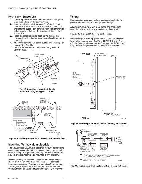
Mounting Surface Mount Models<br />
The <strong>L4006</strong>H and L<strong>60</strong>06C are designed for surface mounting<br />
on piping or tanks. Mount the controller directly on the tank<br />
surface using the adjustable mounting bracket as shown in<br />
Fig. 18. The controller can be mounted in any position.<br />
When mounting the <strong>L4006</strong>H or L<strong>60</strong>06C on piping, the pipe<br />
should be 1 in. (25 mm) diameter or larger for accurate<br />
temperature sensing. Remove any insulation from the pipe.<br />
Thoroughly scrape off all scale, rust, or paint. Mount the<br />
controller using adjustable bracket provided. Turn on power.<br />
2<br />
1<br />
24 VOLT<br />
THERMOSTAT<br />
LOW WATER<br />
CUTOFF<br />
<strong>L4006</strong>A OR<br />
L4007A<br />
LOW LIMIT<br />
AQUASTAT ®<br />
CONTROLLER<br />
GAS<br />
VALVE<br />
PRESSURE<br />
CONTROL<br />
PILOTSTAT<br />
CONTROL<br />
POWER SUPPLY. PROVIDE DISCONNECT MEANS AND<br />
OVERLOAD PROTECTION AS REQUIRED.<br />
L1<br />
(HOT)<br />
L2<br />
1<br />
2 USE <strong>L4006</strong>E FOR MANUAL RESET.<br />
M2856B<br />
Fig. 19. Typical gas-fired system with domestic hot water.<br />
<strong>60</strong>-<strong>2<strong>10</strong>4</strong>—<strong>10</strong> 12


