Reference Manual - clv490.pdf - Machine Vision Components
Reference Manual - clv490.pdf - Machine Vision Components
Reference Manual - clv490.pdf - Machine Vision Components

Create successful ePaper yourself
Turn your PDF publications into a flip-book with our unique Google optimized e-Paper software.
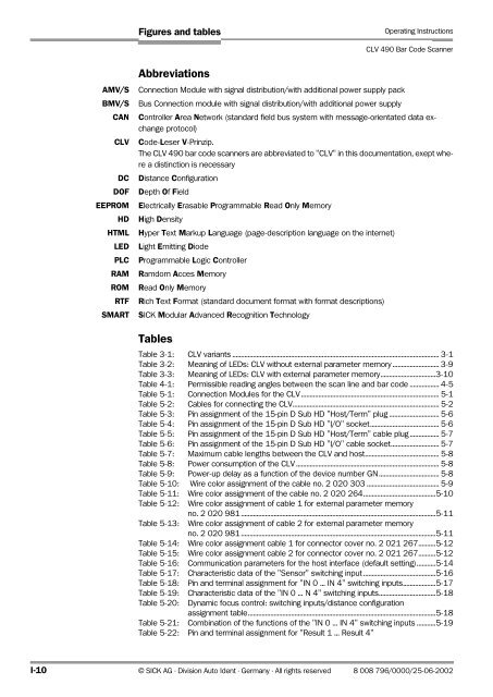
Figures and tables<br />
Operating Instructions<br />
CLV 490 Bar Code Scanner<br />
AMV/S<br />
BMV/S<br />
CAN<br />
CLV<br />
DC<br />
DOF<br />
EEPROM<br />
HD<br />
HTML<br />
LED<br />
PLC<br />
RAM<br />
ROM<br />
RTF<br />
SMART<br />
Abbreviations<br />
Connection Module with signal distribution/with additional power supply pack<br />
Bus Connection module with signal distribution/with additional power supply<br />
Controller Area Network (standard field bus system with message-orientated data exchange<br />
protocol)<br />
Code-Leser V-Prinzip.<br />
The CLV 490 bar code scanners are abbreviated to "CLV" in this documentation, exept where<br />
a distinction is necessary<br />
Distance Configuration<br />
Depth Of Field<br />
Electrically Erasable Programmable Read Only Memory<br />
High Density<br />
Hyper Text Markup Language (page-description language on the internet)<br />
Light Emitting Diode<br />
Programmable Logic Controller<br />
Ramdom Acces Memory<br />
Read Only Memory<br />
Rich Text Format (standard document format with format descriptions)<br />
SICK Modular Advanced Recognition Technology<br />
Tables<br />
Table 3-1: CLV variants ........................................................................................................................ 3-1<br />
Table 3-2: Meaning of LEDs: CLV without external parameter memory........................... 3-9<br />
Table 3-3: Meaning of LEDs: CLV with external parameter memory................................3-10<br />
Table 4-1: Permissible reading angles between the scan line and bar code ................. 4-5<br />
Table 5-1: Connection Modules for the CLV ................................................................................ 5-1<br />
Table 5-2: Cables for connecting the CLV..................................................................................... 5-2<br />
Table 5-3: Pin assignment of the 15-pin D Sub HD "Host/Term" plug ............................. 5-6<br />
Table 5-4: Pin assignment of the 15-pin D Sub HD "I/O" socket........................................ 5-6<br />
Table 5-5: Pin assignment of the 15-pin D Sub HD "Host/Term" cable plug ................. 5-7<br />
Table 5-6: Pin assignment of the 15-pin D Sub HD "I/O" cable socket............................ 5-7<br />
Table 5-7: Maximum cable lengths between the CLV and host........................................... 5-8<br />
Table 5-8: Power consumption of the CLV ................................................................................... 5-8<br />
Table 5-9: Power-up delay as a function of the device number GN................................... 5-8<br />
Table 5-10: Wire color assignment of the cable no. 2 020 303 .......................................... 5-9<br />
Table 5-11: Wire color assignment of the cable no. 2 020 264..........................................5-10<br />
Table 5-12: Wire color assignment of cable 1 for external parameter memory<br />
no. 2 020 981 .................................................................................................................5-11<br />
Table 5-13: Wire color assignment of cable 2 for external parameter memory<br />
no. 2 020 981 .................................................................................................................5-11<br />
Table 5-14: Wire color assignment cable 1 for connector cover no. 2 021 267..........5-12<br />
Table 5-15: Wire color assignment cable 2 for connector cover no. 2 021 267..........5-12<br />
Table 5-16: Communication parameters for the host interface (default setting)...........5-14<br />
Table 5-17: Characteristic data of the "Sensor" switching input ..........................................5-16<br />
Table 5-18: Pin and terminal assignment for "IN 0 ... IN 4" switching inputs...................5-17<br />
Table 5-19: Characteristic data of the "IN 0 ... N 4" switching inputs.................................5-18<br />
Table 5-20: Dynamic focus control: switching inputs/distance configuration<br />
assignment table.............................................................................................................5-18<br />
Table 5-21: Combination of the functions of the "IN 0 ... IN 4" switching inputs ...........5-19<br />
Table 5-22: Pin and terminal assignment for "Result 1 ... Result 4"<br />
I-10 © SICK AG · Division Auto Ident · Germany · All rights reserved 8 008 796/0000/25-06-2002