Reference Manual - clv490.pdf - Machine Vision Components
Reference Manual - clv490.pdf - Machine Vision Components
Reference Manual - clv490.pdf - Machine Vision Components

Create successful ePaper yourself
Turn your PDF publications into a flip-book with our unique Google optimized e-Paper software.
Chapter 4<br />
Installation<br />
Operating Instructions<br />
CLV 490 Bar Code Scanner<br />
Show CP Limits<br />
The "Show CP Limits" operating mode allows you to test whether the desired effect was produced<br />
by narrowing the scan line’s active evaluation range. The CLV alternatively hides certain<br />
parts of the scan line in accordance with the selected min. and max. values of the code<br />
position.<br />
For activation of this operating mode and for checking, See Chapter 6.5.5 Show CP-limits,<br />
Page 6-26.<br />
4.4 Mounting the external components<br />
4.4.1 Mounting the AMV/S 60 Connection Module<br />
1. Mount the AMV/S 60 Connection Module near the CLV.<br />
The distance between the AMV/S 60 and CLV should not exceed max. 10 m.<br />
2. Mount the AMV/S 60 in such a way that accessed to the open device is always possible.<br />
The terminal interface of the CLV is accessed via the internal "Service" plug.<br />
Detailed information on the mounting and electrical installation procedures is provided in the<br />
Operating Instructions for the "AMV/S 60 Connection Module" (order no. 8 008 296).<br />
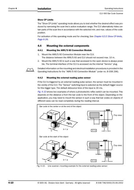
4.4.2 Mounting the external reading pulse sensor<br />
If the CLV is triggered by an external reading pulse sensor, the sensor must be mounted in<br />
the vicinity of the CLV. The "Sensor" switching input is selected as the default trigger source<br />
for this trigger type. The default debounce time of the input is 30 ms.<br />
Fig. 4-10 shows two examples of where a photoelectric reflex switch can be mounted. This<br />
depends on the distance a from the bar code to the front of the object. Depending on the<br />
application, you may need to mount the sensor in such a way that bar codes on objects of<br />
different sizes can be read completely during the reading interval.<br />
Bar code in the center or at the end of the object<br />
a<br />
(Top view)<br />
a<br />
b<br />
b < a<br />
b < a<br />
b<br />
Bar code at the start of the object<br />
aa<br />
(Top view)<br />
a<br />
b<br />
b < a<br />
b < a<br />
b<br />
Fig. 4-10:<br />
Line scanner: mounting example for the external reading pulse sensor<br />
4-10 © SICK AG · Division Auto Ident · Germany · All rights reserved 8 008 796/0000/25-06-2002