NI USB 6008.pdf
NI USB 6008.pdf
NI USB 6008.pdf

Create successful ePaper yourself
Turn your PDF publications into a flip-book with our unique Google optimized e-Paper software.
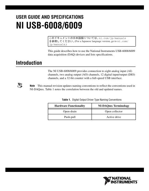
USER GUIDE AND SPECIFICATIONS<br />
<strong>NI</strong> <strong>USB</strong>-6008/6009<br />
Introduction<br />
This guide describes how to use the National Instruments <strong>USB</strong>-6008/6009<br />
data acquisition (DAQ) devices and lists specifications.<br />
The <strong>NI</strong> <strong>USB</strong>-6008/6009 provides connection to eight analog input (AI)<br />
channels, two analog output (AO) channels, 12 digital input/output (DIO)<br />
channels, and a 32-bit counter with a full-speed <strong>USB</strong> interface.<br />
Note This manual revision updates naming conventions to reflect the conventions used in<br />
<strong>NI</strong>-DAQmx. Table 1 notes the correlation between the old and updated names.<br />
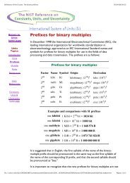
Table 1. Digital Output Driver Type Naming Conventions<br />
Hardware Functionality<br />
Open-drain<br />
Push-pull<br />
<strong>NI</strong>-DAQmx Terminology<br />
Open collector<br />
Active drive
AI Resolution<br />
Table 2. Differences Between the <strong>NI</strong> <strong>USB</strong>-6008 and <strong>NI</strong> <strong>USB</strong>-6009<br />
Feature <strong>NI</strong> <strong>USB</strong>-6008 <strong>NI</strong> <strong>USB</strong>-6009<br />
12 bits differential,<br />
11 bits single-ended<br />
14 bits differential,<br />
13 bits single-ended<br />
Maximum AI Sample Rate,<br />
10 kS/s 48 kS/s<br />
Single Channel *<br />
Maximum AI Sample Rate,<br />
10 kS/s 48 kS/s<br />
Multiple Channels (Aggregate) *<br />
DIO Configuration Open collector Open collector or active drive<br />
*<br />
System dependent.<br />
1<br />
1 Analog 16<br />
<strong>NI</strong> <strong>USB</strong>-6009<br />
8 Inputs, 14-bit, Multifunction I/O<br />
32 Digital 17<br />
1 <strong>USB</strong> Cable Strain Relief<br />
Figure 1. <strong>NI</strong> <strong>USB</strong>-6008/6009<br />
Figure 2. <strong>NI</strong> <strong>USB</strong>-6008/6009 Back View<br />
<strong>NI</strong> <strong>USB</strong>-6008/6009 User Guide and Specifications 2 ni.com
Safety Guidelines<br />
Caution<br />
Operate the hardware only as described in these operating instructions.<br />
The following section contains important safety information that you must<br />
follow when installing and using the <strong>NI</strong> <strong>USB</strong>-6008/6009.<br />
Do not operate the <strong>NI</strong> <strong>USB</strong>-6008/6009 in a manner not specified in this<br />
document. Misuse of the device can result in a hazard. You can compromise<br />
the safety protection built into the device if the device is damaged in any<br />
way. If the device is damaged, contact National Instruments for repair.<br />
Do not substitute parts or modify the device except as described in this<br />
document. Use the device only with the chassis, modules, accessories, and<br />
cables specified in the installation instructions. You must have all covers<br />
and filler panels installed during operation of the device.<br />
Do not operate the device in an explosive atmosphere or where there may<br />
be flammable gases or fumes. If you must operate the device in such an<br />
environment, it must be in a suitably rated enclosure.<br />
If you need to clean the device, use a dry cloth. Make sure that the device<br />
is completely dry and free from contaminants before returning it to service.<br />
Operate the device only at or below Pollution Degree 2. Pollution is foreign<br />
matter in a solid, liquid, or gaseous state that can reduce dielectric strength<br />
or surface resistivity. The following is a description of pollution degrees:<br />
• Pollution Degree 1 means no pollution or only dry, nonconductive<br />
pollution occurs. The pollution has no influence.<br />
• Pollution Degree 2 means that only nonconductive pollution occurs in<br />
most cases. Occasionally, however, a temporary conductivity caused<br />
by condensation must be expected.<br />
• Pollution Degree 3 means that conductive pollution occurs, or dry,<br />
nonconductive pollution occurs that becomes conductive due to<br />
condensation.<br />
You must insulate signal connections for the maximum voltage for which<br />
the device is rated. Do not exceed the maximum ratings for the device. Do<br />
not install wiring while the device is live with electrical signals. Do not<br />
remove or add connector blocks when power is connected to the system.<br />
Avoid contact between your body and the connector block signal when hot<br />
swapping modules. Remove power from signal lines before connecting<br />
them to or disconnecting them from the device.<br />
© National Instruments Corporation 3 <strong>NI</strong> <strong>USB</strong>-6008/6009 User Guide and Specifications
Operate the device at or below the Measurement Category I 1 . Measurement<br />
circuits are subjected to working voltages 2 and transient stresses<br />
(overvoltage) from the circuit to which they are connected during<br />
measurement or test. Measurement categories establish standard impulse<br />
withstand voltage levels that commonly occur in electrical distribution<br />
systems. The following is a description of measurement categories:<br />
• Measurement Category I is for measurements performed on circuits<br />
not directly connected to the electrical distribution system referred to<br />
as MAINS 3 voltage. This category is for measurements of voltages<br />
from specially protected secondary circuits. Such voltage<br />
measurements include signal levels, special equipment, limited-energy<br />
parts of equipment, circuits powered by regulated low-voltage sources,<br />
and electronics.<br />
• Measurement Category II is for measurements performed on circuits<br />
directly connected to the electrical distribution system. This category<br />
refers to local-level electrical distribution, such as that provided by a<br />
standard wall outlet (for example, 115 V for U.S. or 230 V for Europe).<br />
Examples of Measurement Category II are measurements performed<br />
on household appliances, portable tools, and similar E Series devices.<br />
• Measurement Category III is for measurements performed in the<br />
building installation at the distribution level. This category refers to<br />
measurements on hard-wired equipment such as equipment in fixed<br />
installations, distribution boards, and circuit breakers. Other examples<br />
are wiring, including cables, bus-bars, junction boxes, switches,<br />
socket-outlets in the fixed installation, and stationary motors with<br />
permanent connections to fixed installations.<br />
• Measurement Category IV is for measurements performed at the<br />
primary electrical supply installation (
Software<br />
Software support for the <strong>NI</strong> <strong>USB</strong>-6008/6009 for Windows 2000/XP/Vista<br />
is provided by <strong>NI</strong>-DAQmx.<br />
The <strong>NI</strong>-DAQmx CD contains example programs that you can use to get<br />
started programming with the <strong>NI</strong> <strong>USB</strong>-6008/6009. Refer to the <strong>NI</strong>-DAQmx<br />
for <strong>USB</strong> Devices Getting Started Guide, that shipped with your device and<br />
is also accessible from Start»All Programs»National Instruments»<br />
<strong>NI</strong>-DAQ for more information.<br />
Note For information about non-Windows operating system support, refer to<br />
ni.com/info and enter rddqld.<br />
LabVIEW SignalExpress for DAQ<br />
The <strong>NI</strong>-DAQmx CD includes LabVIEW SignalExpress for DAQ which is<br />
an interactive, measurement software tool for quickly acquiring, analyzing,<br />
and presenting data with no programming required. The application is<br />
available at Start»All Programs»National Instruments»<strong>NI</strong> DAQ»<br />
LabVIEW SignalExpress.<br />
© National Instruments Corporation 5 <strong>NI</strong> <strong>USB</strong>-6008/6009 User Guide and Specifications
Hardware<br />
The following block diagram shows key functional components of the<br />
<strong>NI</strong> <strong>USB</strong>-6008/6009.<br />
Full-Speed <strong>USB</strong> Interface<br />
Vbus<br />
<strong>USB</strong><br />
External<br />
Power<br />
Supply<br />
<strong>USB</strong> Microcontroller<br />
+5 V/200 mA<br />
PFI 0<br />
P1.<br />
P0.<br />
Digital I/O Terminal Block<br />
+2.5 V/CAL<br />
8 Channel<br />
12/14b ADC<br />
SPI<br />
12b DAC<br />
12b DAC<br />
AI <br />
AO 0<br />
AO 1<br />
Analog I/O Terminal Block<br />
Figure 3. Device Block Diagram<br />
<strong>NI</strong> <strong>USB</strong>-6008/6009 User Guide and Specifications 6 ni.com
Setting Up Hardware<br />
Complete the following steps to set up the hardware:<br />
1. Install combicon screw terminal blocks by inserting them into the<br />
combicon jacks.<br />
2. Figure 4 illustrates the signal labels that ship in the <strong>NI</strong> <strong>USB</strong>-6008/6009<br />
kit. You can apply the signal labels to the screw terminal blocks for<br />
easy signal identification.<br />
3<br />
4<br />
1<br />
ANALOG<br />
DIGITAL<br />
2<br />
1 Terminal Number Labels (Use Both Together)<br />
2 Digital I/O Label<br />
3 Single-Ended Label (Use Either)<br />
4 Differential Label (Use Either)<br />
Figure 4. <strong>NI</strong> <strong>USB</strong>-6008/6009 Signal Labels<br />
3. Refer to Table 3 and Figures 4 and 5 for signal label orientation and<br />
affix the provided signal labels to the screw terminal blocks. Until the<br />
signal labels are applied, you can insert the screw terminal blocks into<br />
either of the combicon jacks.<br />
© National Instruments Corporation 7 <strong>NI</strong> <strong>USB</strong>-6008/6009 User Guide and Specifications
igita<br />
1<br />
4<br />
2 3<br />
1<br />
D 7<br />
3 l<br />
3<br />
2<br />
<strong>NI</strong> <strong>USB</strong>-6009<br />
8 Inputs, 14-bit, Multifunction I/O<br />
2<br />
1 A nalo g<br />
1 6<br />
1 Overlay Label with Pin Orientation Guides<br />
2 Combicon Jack<br />
3 Signal Labels<br />
4 <strong>USB</strong> Cable<br />
Figure 5. Signal Label Application Diagram<br />
Note Once you label the screw terminal blocks, you must only insert them into the<br />
matching combicon jack, as indicated by the overlay label on the <strong>NI</strong> <strong>USB</strong>-6008/6009<br />
device.<br />
4. Connect the wiring to the appropriate screw terminals.<br />
<strong>NI</strong> <strong>USB</strong>-6008/6009 User Guide and Specifications 8 ni.com
I/O Connector<br />
The <strong>NI</strong> <strong>USB</strong>-6008/6009 ships with one detachable screw terminal block for<br />
analog signals and one detachable screw terminal block for digital signals.<br />
These terminal blocks provide 16 connections that use 16 AWG to<br />
28 AWG wire.<br />
Table 3 lists the analog terminal assignments, and Table 4 lists the digital<br />
terminal assignments.<br />
Table 3. Analog Terminal Assignments<br />
Module<br />
Terminal<br />
Signal,<br />
Single-Ended Mode<br />
Signal,<br />
Differential Mode<br />
1 GND GND<br />
2 AI 0 AI 0+<br />
3 AI 4 AI 0–<br />
4 GND GND<br />
1 2 3 4 5 6 7 8 9 10 11 12 13 14 15 16<br />
5 AI 1 AI 1+<br />
6 AI 5 AI 1–<br />
7 GND GND<br />
8 AI 2 AI 2+<br />
9 AI 6 AI 2–<br />
10 GND GND<br />
11 AI 3 AI 3+<br />
12 AI 7 AI 3–<br />
13 GND GND<br />
14 AO 0 AO 0<br />
15 AO 1 AO 1<br />
16 GND GND<br />
© National Instruments Corporation 9 <strong>NI</strong> <strong>USB</strong>-6008/6009 User Guide and Specifications
Table 4. Digital Terminal Assignments<br />
Module Terminal Signal<br />
17 P0.0<br />
18 P0.1<br />
19 P0.2<br />
32 31 30 29 28 27 26 25 24 23 22 21 20 19 18 17<br />
20 P0.3<br />
21 P0.4<br />
22 P0.5<br />
23 P0 6<br />
24 P0.7<br />
25 P1.0<br />
26 P1.1<br />
27 P1.2<br />
28 P1.3<br />
29 PFI 0<br />
30 +2.5 V<br />
31 +5 V<br />
32 GND<br />
<strong>NI</strong> <strong>USB</strong>-6008/6009 User Guide and Specifications 10 ni.com
Signal Descriptions<br />
Table 5 describes the signals available on the I/O connectors.<br />
Table 5. Signal Descriptions<br />
Signal Name Reference Direction Description<br />
GND — — Ground—The reference point for the<br />
single-ended AI measurements, bias<br />
current return point for differential mode<br />
measurements, AO voltages, digital<br />
signals at the I/O connector, +5 VDC<br />
supply, and the +2.5 VDC reference.<br />
AI Varies Input Analog Input Channels 0 to 7—For<br />
single-ended measurements, each signal is<br />
an analog input voltage channel. For<br />
differential measurements, AI 0 and AI 4<br />
are the positive and negative inputs of<br />
differential analog input channel 0.<br />
The following signal pairs also form<br />
differential input channels:<br />
, , and<br />
.<br />
AO 0 GND Output Analog Channel 0 Output—Supplies the<br />
voltage output of AO channel 0.<br />
AO 1 GND Output Analog Channel 1 Output—Supplies the<br />
voltage output of AO channel 1.<br />
P1.<br />
P0.<br />
GND<br />
Input or<br />
Output<br />
Digital I/O Signals—You can<br />
individually configure each signal as an<br />
input or output.<br />
+2.5 V GND Output +2.5 V External Reference—Provides a<br />
reference for wrap-back testing.<br />
+5 V GND Output +5 V Power Source—Provides +5 V<br />
power up to 200 mA.<br />
PFI 0 GND Input PFI 0—This pin is configurable as either a<br />
digital trigger or an event counter input.<br />
© National Instruments Corporation 11 <strong>NI</strong> <strong>USB</strong>-6008/6009 User Guide and Specifications
LED<br />
The <strong>NI</strong> <strong>USB</strong>-6008/6009 device has a green LED next to the <strong>USB</strong><br />
connector. When the device is connected to a <strong>USB</strong> port, the LED blinks<br />
steadily to indicate that the device is initialized and is receiving power from<br />
the connection.<br />
If the LED is not blinking, it may mean that the device is not initialized or<br />
the computer is in standby mode. In order for the device to be recognized,<br />
the device must be connected to a computer that has <strong>NI</strong>-DAQmx installed<br />
on it. If your device is not blinking, make sure your computer has the latest<br />
version of <strong>NI</strong>-DAQmx installed on it, and the computer is not in standby<br />
mode.<br />
Analog Input<br />
Analog Input Circuitry<br />
You can connect analog input signals to the <strong>NI</strong> <strong>USB</strong>-6008/6009 through<br />
the I/O connector. Refer to Table 5 for more information about connecting<br />
analog input signals.<br />
Figure 6 illustrates the analog input circuitry of the <strong>NI</strong> <strong>USB</strong>-6008/6009.<br />
+2.5 V REF<br />
AI<br />
127 kΩ<br />
30.9 kΩ MUX PGA<br />
ADC<br />
AI FIFO<br />
39.2 kΩ<br />
Input Range<br />
Selection<br />
MUX<br />
Figure 6. Analog Input Circuitry<br />
The <strong>NI</strong> <strong>USB</strong> 6008/6009 has one analog-to-digital converter (ADC). The<br />
multiplexer (MUX) routes one AI channel at a time to the PGA.<br />
<strong>NI</strong> <strong>USB</strong>-6008/6009 User Guide and Specifications 12 ni.com
Analog Input Modes<br />
PGA<br />
The progammable-gain amplifier provides input gains of 1, 2, 4, 5, 8,<br />
10, 16, or 20 when configured for differential measurements and gain<br />
of 1 when configured for single-ended measurements. The PGA gain is<br />
automatically calculated based on the voltage range selected in the<br />
measurement application.<br />
A/D Converter<br />
The analog-to-digital converter (ADC) digitizes the AI signal by<br />
converting the analog voltage into a digital code.<br />
AI FIFO<br />
The <strong>NI</strong> <strong>USB</strong>-6008/6009 can perform both single and multiple A/D<br />
conversions of a fixed or infinite number of samples. A first-in-first-out<br />
(FIFO) buffer holds data during AI acquisitions to ensure that no data<br />
is lost.<br />
You can configure the AI channels on the <strong>NI</strong> <strong>USB</strong>-6008/6009 to take<br />
single-ended or differential measurements. Refer to Table 5 for more<br />
information about I/O connections for single-ended or differential<br />
measurements.<br />
Connecting Differential Voltage Signals<br />
For differential signals, connect the positive lead of the signal to the AI+<br />
terminal, and the negative lead to the AI– terminal.<br />
AI+<br />
Voltage<br />
Source<br />
<strong>NI</strong> <strong>USB</strong>-6008/6009<br />
AI–<br />
Figure 7. Connecting a Differential Voltage Signal<br />
© National Instruments Corporation 13 <strong>NI</strong> <strong>USB</strong>-6008/6009 User Guide and Specifications
The differential input mode can measure ±20 V signals in the ±20 V range.<br />
However, the maximum voltage on any one pin is ±10 V with respect to<br />
GND. For example, if AI 1 is +10 V and AI 5 is –10 V, then the<br />
measurement returned from the device is +20 V.<br />
20<br />
15<br />
10<br />
Amplitude (V)<br />
5<br />
0<br />
–5<br />
–10<br />
AI 1<br />
AI 5<br />
Result<br />
–15<br />
–20<br />
Figure 8. Example of a Differential 20 V Measurement<br />
Connecting a signal greater than ±10 V on either pin results in a clipped<br />
output.<br />
20<br />
15<br />
10<br />
Amplitude (V)<br />
5<br />
0<br />
–5<br />
–10<br />
AI 1<br />
AI 5<br />
Result<br />
–15<br />
–20<br />
Figure 9. Exceeding ±10 V on AI Returns Clipped Output<br />
<strong>NI</strong> <strong>USB</strong>-6008/6009 User Guide and Specifications 14 ni.com
Connecting Reference Single-Ended Voltage Signals<br />
To connect reference single-ended voltage signals (RSE) to the<br />
<strong>NI</strong> <strong>USB</strong>-6008/6009, connect the positive voltage signal to the desired<br />
AI terminal, and the ground signal to a GND terminal.<br />
When no signals are connected to the analog input terminal, the internal<br />
resistor divider may cause the terminal to float to approximately 1.4 V<br />
when the analog input terminal is configured as RSE. This behavior is<br />
normal and does not affect the measurement when a signal is connected.<br />
AI<br />
Voltage<br />
Source<br />
<strong>NI</strong> <strong>USB</strong>-6008/6009<br />
GND<br />
Figure 10. Connecting a Reference Single-Ended Voltage Signal<br />
Digital Trigger<br />
When an AI task is defined, you can configure PFI 0 as a digital trigger<br />
input. When the digital trigger is enabled, the AI task waits for a rising or<br />
falling edge on PFI 0 before starting the acquisition. To use ai/Start Trigger<br />
with a digital source, specify PFI 0 as the source and select rising or falling<br />
edge.<br />
© National Instruments Corporation 15 <strong>NI</strong> <strong>USB</strong>-6008/6009 User Guide and Specifications
Analog Output<br />
Analog Output Circuitry<br />
The <strong>NI</strong> <strong>USB</strong>-6008/6009 has two independent AO channels that can<br />
generate outputs from 0–5 V. All updates of AO lines are software-timed.<br />
Figure 11 illustrates the analog output circuitry for the <strong>NI</strong> <strong>USB</strong>-6008/6009.<br />
+5 V<br />
REF(+) REF(–)<br />
12-Bit<br />
DAC<br />
Output<br />
Buffer<br />
50 Ω<br />
AO<br />
GND<br />
DACs<br />
Connecting Analog Output Loads<br />
Figure 11. Analog Output Circuitry<br />
Digital-to-analog converts (DACs) convert digital codes to analog<br />
voltages.<br />
To connect loads to the <strong>NI</strong> <strong>USB</strong>-6008/6009, connect the positive lead of the<br />
load to the AO terminal, and connect the ground of the load to a GND<br />
terminal.<br />
AI<br />
Voltage<br />
Source<br />
<strong>NI</strong> <strong>USB</strong>-6008/6009<br />
GND<br />
Figure 12. Connecting a Load<br />
<strong>NI</strong> <strong>USB</strong>-6008/6009 User Guide and Specifications 16 ni.com
Minimizing Glitches on the Output Signal<br />
Digital I/O<br />
Digital I/O Circuitry<br />
When you use a DAC to generate a waveform, you may observe glitches in<br />
the output signal. These glitches are normal; when a DAQ switches from<br />
one voltage to another, it produces glitches due to released charges. The<br />
largest glitches occur when the most significant bit of the DAC code<br />
changes. You can build a lowpass deglitching filter to remove some of<br />
these glitches, depending on the frequency and nature of the output signal.<br />
Refer to ni.com/support for more information about minimizing<br />
glitches.<br />
The <strong>NI</strong> <strong>USB</strong>-6008/6009 has 12 digital lines, P0. and P1.,<br />
which comprise the DIO port. GND is the ground-reference signal for the<br />
DIO port. You can individually program all lines as inputs or outputs.<br />
Figure 13 shows P0. connected to example signals configured as<br />
digital inputs and digital outputs. You can configure P1. similarly.<br />
+5 V<br />
1<br />
LED<br />
2<br />
3<br />
4<br />
LED<br />
+5 V<br />
Switch<br />
TTL Signal<br />
P0.0<br />
P0.1<br />
P0.2<br />
P0.3<br />
P0.4<br />
P0.5<br />
P0.6<br />
P0.7<br />
I/O Connector<br />
GND<br />
1 P0.0 configured as an open collector digital output driving a LED<br />
2 P0.2 configured as a active drive digital output driving a LED<br />
3 P0.4 configured as a digital input receiving a TTL signal from a gated invertor<br />
4 P0.7 configured as a digital input receiving a 0 V or 5 V signal from a switch<br />
Figure 13. Example of Connecting a Load<br />
© National Instruments Corporation 17 <strong>NI</strong> <strong>USB</strong>-6008/6009 User Guide and Specifications
Caution Exceeding the maximum input voltage ratings or maximum output ratings, which<br />
are listed in the Specifications section, can damage the DAQ device and the computer.<br />
National Instruments is not liable for any damage resulting from such signal connections.<br />
Source/Sink Information<br />
The default configuration of the <strong>NI</strong> <strong>USB</strong>-6008/6009 DIO ports is open<br />
collector, allowing 5 V operation, with an onboard 4.7 kΩ pull-up resistor.<br />
An external, user-provided, pull-up resistor can be added to increase the<br />
source current drive up to a 8.5 mA limit per line as shown in Figure 14.<br />
The <strong>NI</strong> <strong>USB</strong>-6009 ports can also be configured as active drive using the<br />
DAQmx API, allowing 3.3 V operation with a source/sink current limit of<br />
±8.5 mA. Refer to the <strong>NI</strong>-DAQmx Help for more information about how to<br />
set the DIO configuration.<br />
+5 V<br />
<strong>NI</strong> <strong>USB</strong>-6008/6009<br />
+5 V<br />
Re<br />
External<br />
Pull-up<br />
Resistor<br />
P0.0<br />
Rp<br />
4.7 KΩ Onboard Resistor<br />
Port Pad<br />
Rl<br />
Load<br />
A<br />
GND<br />
Figure 14. Example of Connecting External User-Provided Resistor<br />
Complete the following steps to determine the value of the user-provided<br />
pull-up resistor:<br />
1. Place an ammeter in series with the load.<br />
2. Place a variable resistor between the digital output line and the +5 V.<br />
3. Adjust the variable resistor until the ammeter current reads as the<br />
intended current. The intended current must be less than 8.5 mA.<br />
4. Remove the ammeter and variable resistor from your circuit.<br />
5. Measure the resistance of the variable resistor. The measured<br />
resistance is the ideal value of the pull-up resistor.<br />
<strong>NI</strong> <strong>USB</strong>-6008/6009 User Guide and Specifications 18 ni.com
6. Select a static resistor value for your pull-up resistor that is greater than<br />
or equal to the ideal resistance.<br />
7. Re-connect the load circuit and the pull-up resistor.<br />
I/O Protection<br />
To protect the <strong>NI</strong> <strong>USB</strong>-6008/6009 against overvoltage, undervoltage, and<br />
overcurrent conditions, as well as ESD events, you should avoid these fault<br />
conditions by using the following guidelines:<br />
• If you configure a DIO line as an output, do not connect it to any<br />
external signal source, ground signal, or power supply.<br />
• If you configure a DIO line as an output, understand the current<br />
requirements of the load connected to these signals. Do not exceed<br />
the specified current output limits of the DAQ device.<br />
National Instruments has several signal conditioning solutions for<br />
digital applications requiring high current drive.<br />
• If you configure a DIO line as an input, do not drive the line with<br />
voltages outside of its normal operating range. The DIO lines have<br />
a smaller operating range than the AI signals.<br />
• Treat the DAQ device as you would treat any static sensitive device.<br />
Always properly ground yourself and the equipment when handling<br />
the DAQ device or connecting to it.<br />
Power-On States<br />
Static DIO<br />
At system startup and reset, the hardware sets all DIO lines to<br />
high-impedance inputs. The DAQ device does not drive the signal<br />
high or low. Each line has a weak pull-up resistor connected to it.<br />
Each of the <strong>NI</strong> <strong>USB</strong>-6008/6009 DIO lines can be used as a static DI or DO<br />
line. You can use static DIO lines to monitor or control digital signals. All<br />
samples of static DI lines and updates of DO lines are software-timed.<br />
Event Counter<br />
You can configure PFI 0 as a source for a gated invertor counter input edge<br />
count task. In this mode, falling-edge events are counted using a 32-bit<br />
counter. For more information about event timing requirements, refer to the<br />
Specifications section.<br />
© National Instruments Corporation 19 <strong>NI</strong> <strong>USB</strong>-6008/6009 User Guide and Specifications
Reference and Power Sources<br />
+2.5 External References<br />
+5 V Power Source<br />
The <strong>NI</strong> <strong>USB</strong>-6008/6009 creates an external reference and supplies a power<br />
source. All voltages are relative to COM unless otherwise noted.<br />
The <strong>NI</strong> <strong>USB</strong>-6008/6009 creates a high-purity reference voltage supply for<br />
the ADC using a multi-state regulator, amplifier, and filter circuit. The<br />
resulting +2.5 V reference voltage can be used as a signal for self test.<br />
The <strong>NI</strong> <strong>USB</strong>-6008/6009 supplies a 5 V, 200 mA output. This source can be<br />
used to power external components.<br />
Note<br />
While the device is in <strong>USB</strong> suspend, the output is disabled.<br />
Specifications<br />
The following specifications are typical at 25 °C, unless otherwise noted.<br />
Analog Input<br />
Converter type ........................................Successive approximation<br />
Analog inputs..........................................8 single-ended, 4 differential,<br />
software selectable<br />
Input resolution<br />
<strong>NI</strong> <strong>USB</strong>-6008...................................12 bits differential,<br />
11 bits single-ended<br />
<strong>NI</strong> <strong>USB</strong>-6009...................................14 bits differential,<br />
13 bits single-ended<br />
Max sampling rate 1<br />
<strong>NI</strong> <strong>USB</strong>-6008...................................10 kS/s<br />
<strong>NI</strong> <strong>USB</strong>-6009...................................48 kS/s<br />
AI FIFO ..................................................512 bytes<br />
Timing resolution ...................................41.67 ns (24 MHz timebase)<br />
1<br />
System dependent.<br />
<strong>NI</strong> <strong>USB</strong>-6008/6009 User Guide and Specifications 20 ni.com
Timing accuracy..................................... 100 ppm of actual sample rate<br />
Input range<br />
Single-ended ................................... ±10 V<br />
Differential...................................... ±20 V 1 , ±10 V, ±5 V, ±4 V,<br />
±2.5 V, ±2 V, ±1.25 V, ±1 V<br />
Working voltage..................................... ±10 V<br />
Input impedance..................................... 144 kΩ<br />
Overvoltage protection........................... ±35<br />
Trigger source ........................................ Software or external digital<br />
trigger<br />
System noise 2<br />
Single-ended<br />
±10 V range ............................. 5 mVrms<br />
Differential<br />
±20 V range............................. 5 mVrms<br />
±1 V range ............................... 0.5 mVrms<br />
Absolute accuracy at full scale, single ended<br />
Range<br />
Typical at 25 °C<br />
(mV)<br />
Maximum over Temperature<br />
(mV)<br />
±10 14.7 138<br />
Absolute accuracy at full scale, differential 3<br />
Range<br />
Typical at 25 °C<br />
(mV)<br />
Maximum over Temperature<br />
(mV)<br />
±20 14.7 138<br />
±10 7.73 84.8<br />
±5 4.28 58.4<br />
±4 3.59 53.1<br />
±2.5 2.56 45.1<br />
1<br />
±20 V means that |AI+ – (AI–)|
Range<br />
Typical at 25 °C<br />
(mV)<br />
Maximum over Temperature<br />
(mV)<br />
Analog Output<br />
±2 2.21 42.5<br />
±1.25 1.70 38.9<br />
±1 1.53 37.5<br />
Analog outputs........................................2<br />
Output resolution ....................................12 bits<br />
Maximum update rate.............................150 Hz, software-timed<br />
Output range ...........................................0 to +5 V<br />
Output impedance...................................50 Ω<br />
Output current drive................................5 mA<br />
Power-on state ........................................0 V<br />
Slew rate .................................................1 V/μs<br />
Short circuit current ................................50 mA<br />
Absolute accuracy (no load) ...................7 mV typical, 36.4 mV maximum<br />
at full scale<br />
Digital I/O<br />
Digital I/O<br />
P0. .........................................8 lines<br />
P1. .........................................4 lines<br />
Direction control.....................................Each channel individually<br />
programmable as input or output<br />
Output driver type<br />
<strong>NI</strong> <strong>USB</strong>-6008...................................Open collector (open-drain)<br />
<strong>NI</strong> <strong>USB</strong>-6009...................................Each channel individually<br />
programmable as active drive<br />
(push-pull) or open collector<br />
(open-drain)<br />
<strong>NI</strong> <strong>USB</strong>-6008/6009 User Guide and Specifications 22 ni.com
Compatibility ......................................... TTL, LVTTL, CMOS<br />
Absolute maximum voltage range ......... –0.5 to 5.8 V with respect to GND<br />
Pull-up resistor ....................................... 4.7 kΩ to 5 V<br />
Power-on state........................................ Input<br />
Digital logic levels<br />
Level Min Max Units<br />
Input low voltage<br />
Input high voltage<br />
Input leakage current<br />
–0.3<br />
2.0<br />
—<br />
0.8<br />
5.8<br />
50<br />
V<br />
V<br />
μA<br />
Output low voltage (I = 8.5 mA)<br />
Output high voltage<br />
Active drive (push-pull), I = –8.5 mA<br />
Open collector (open-drain), I = –0.6 mA, nominal<br />
Open collector (open-drain), I = –8.5 mA, with external<br />
pull-up resistor<br />
—<br />
2.0<br />
2.0<br />
2.0<br />
0.8<br />
3.5<br />
5.0<br />
—<br />
V<br />
V<br />
V<br />
V<br />
External Voltage<br />
+5 V output (200 mA maximum) .......... +5 V typical, +4.85 V minimum<br />
+2.5 V output (1 mA maximum) ........... +2.5 V typical<br />
+2.5 V accuracy ..................................... 0.25% max<br />
Reference temperature drift ................... 50 ppm/°C max<br />
Counter<br />
Number of counters................................ 1<br />
Resolution .............................................. 32 bits<br />
Counter measurements........................... Edge counting (falling-edge)<br />
Counter direction.................................... Count up<br />
Pull-up resistor ....................................... 4.7 kΩ to 5 V<br />
Maximum input frequency..................... 5 MHz<br />
Minimum high pulse width.................... 100 ns<br />
Minimum low pulse width ..................... 100 ns<br />
© National Instruments Corporation 23 <strong>NI</strong> <strong>USB</strong>-6008/6009 User Guide and Specifications
Input high voltage...................................2.0 V<br />
Input low voltage ....................................0.8 V<br />
Bus Interface<br />
<strong>USB</strong> specification ...................................<strong>USB</strong> 2.0 full-speed<br />
Power Requirements<br />
Physical Characteristics<br />
<strong>USB</strong> bus speed........................................12 Mb/s<br />
<strong>USB</strong><br />
4.10 to 5.25 VDC.............................80 mA typical, 500 mA max<br />
<strong>USB</strong> suspend ...................................300 μA typical, 500 μA max<br />
If you need to clean the module, wipe it with a dry towel.<br />
Dimensions<br />
Without connectors..........................6.35 cm × 8.51 cm × 2.31 cm<br />
(2.50 in. × 3.35 in. × 0.91 in.)<br />
With connectors...............................8.18 cm × 8.51 cm × 2.31 cm<br />
(3.22 in. × 3.35 in. × 0.91 in.)<br />
I/O connectors.........................................<strong>USB</strong> series B receptacle,<br />
(2) 16 position terminal block<br />
plug headers<br />
Weight<br />
With connectors...............................84 g (3 oz)<br />
Without connectors..........................54 g (1.9 oz)<br />
Screw-terminal wiring ............................16 to 28 AWG<br />
Torque for screw terminals.....................0.22–0.25 N · m<br />
(2.0–2.2 lb · in.)<br />
<strong>NI</strong> <strong>USB</strong>-6008/6009 User Guide and Specifications 24 ni.com
Safety<br />
Standards<br />
The <strong>NI</strong> <strong>USB</strong>-6008/6009 is designed to meet the requirements of the<br />
following standards of safety for electrical equipment for measurement,<br />
control, and laboratory use:<br />
• IEC 61010-1, EN 61010-1<br />
• UL 61010-1, CSA 61010-1<br />
Note For UL and other safety certifications, refer to the product label, or visit<br />
ni.com/certification, search by model number or product line, and click the<br />
appropriate link in the Certification column.<br />
Voltages<br />
Connect only voltages that are within these limits.<br />
Channel-to-GND.................................... ±30 V max,<br />
Measurement Category I<br />
Measurement Category I is for measurements performed on circuits not<br />
directly connected to the electrical distribution system referred to as<br />
MAINS voltage. MAINS is a hazardous live electrical supply system that<br />
powers equipment. This category is for measurements of voltages from<br />
specially protected secondary circuits. Such voltage measurements include<br />
signal levels, special equipment, limited-energy parts of equipment,<br />
circuits powered by regulated low-voltage sources, and electronics.<br />
Caution Do not use this module for connection to signals or for measurements within<br />
Measurement Categories II, III, or IV.<br />
Hazardous Locations<br />
The <strong>NI</strong> <strong>USB</strong>-6008/6009 are not certified for use in hazardous locations.<br />
Environmental<br />
The <strong>NI</strong> <strong>USB</strong>-6008/6009 device is intended for indoor use only.<br />
Operating temperature<br />
(IEC 60068-2-1 and IEC 60068-2-2) ..... 0 to 55 °C<br />
Operating humidity<br />
(IEC 60068-2-56)................................... 5 to 95% RH, noncondensing<br />
Maximum altitude .................................. 2,000 m (at 25 °C ambient<br />
temperature)<br />
© National Instruments Corporation 25 <strong>NI</strong> <strong>USB</strong>-6008/6009 User Guide and Specifications
Electromagnetic Compatibility<br />
Storage temperature<br />
(IEC 60068-2-1 and IEC 60068-2-2)......–40 to 85 °C<br />
Storage humidity<br />
(IEC 60068-2-56) ..................................5 to 90% RH, noncondensing<br />
Pollution Degree (IEC 60664)................2<br />
This product is designed to meet the requirements of the following<br />
standards of EMC for electrical equipment for measurement, control,<br />
and laboratory use:<br />
• EN 61326 EMC requirements; Minimum Immunity<br />
• EN 55011 Emissions; Group 1, Class A<br />
• CE, C-Tick, ICES, and FCC Part 15 Emissions; Class A<br />
Note The <strong>NI</strong> <strong>USB</strong>-6008/6009 may experience temporary variations in analog input<br />
readings when exposed to radiated and conducted RF noise. The device returns to normal<br />
operation after RF exposure is removed.<br />
Note<br />
For EMC compliance, operate this device according to product documentation.<br />
CE Compliance<br />
This product meets the essential requirements of applicable European<br />
Directives, as amended for CE marking, as follows:<br />
• 73/23/EEC; Low-Voltage Directive (safety)<br />
• 89/336/EEC; Electromagnetic Compatibility Directive (EMC)<br />
Note Refer to the Declaration of Conformity (DoC) for this product for any additional<br />
regulatory compliance information. To obtain the DoC for this product, visit ni.com/<br />
certification, search by model number or product line, and click the appropriate link<br />
in the Certification column.<br />
Waste Electrical and Electronic Equipment (WEEE)<br />
EU Customers At the end of their life cycle, all products must be sent to a WEEE recycling<br />
center. For more information about WEEE recycling centers and National Instruments<br />
WEEE initiatives, visit ni.com/environment/weee.htm.<br />
<strong>NI</strong> <strong>USB</strong>-6008/6009 User Guide and Specifications 26 ni.com
Where to Go for Support<br />
The National Instruments Web site is your complete resource for technical<br />
support. At ni.com/support you have access to everything from<br />
troubleshooting and application development self-help resources to email<br />
and phone assistance from <strong>NI</strong> Application Engineers.<br />
A Declaration of Conformity (DoC) is our claim of compliance with the<br />
Council of the European Communities using the manufacturer’s<br />
declaration of conformity. This system affords the user protection for<br />
electronic compatibility (EMC) and product safety. You can obtain the DoC<br />
for your product by visiting ni.com/certification. If your product<br />
supports calibration, you can obtain the calibration certificate for your<br />
product at ni.com/calibration.<br />
National Instruments corporate headquarters is located at<br />
11500 North Mopac Expressway, Austin, Texas, 78759-3504.<br />
National Instruments also has offices located around the world to help<br />
address your support needs. For telephone support in the United States,<br />
create your service request at ni.com/support and follow the calling<br />
instructions or dial 512 795 8248. For telephone support outside the United<br />
States, contact your local branch office:<br />
Australia 1800 300 800, Austria 43 662 457990-0,<br />
Belgium 32 (0) 2 757 0020, Brazil 55 11 3262 3599,<br />
Canada 800 433 3488, China 86 21 5050 9800,<br />
Czech Republic 420 224 235 774, Denmark 45 45 76 26 00,<br />
Finland 385 (0) 9 725 72511, France 01 57 66 24 24,<br />
Germany 49 89 7413130, India 91 80 41190000, Israel 972 3 6393737,<br />
Italy 39 02 413091, Japan 81 3 5472 2970, Korea 82 02 3451 3400,<br />
Lebanon 961 (0) 1 33 28 28, Malaysia 1800 887710,<br />
Mexico 01 800 010 0793, Netherlands 31 (0) 348 433 466,<br />
New Zealand 0800 553 322, Norway 47 (0) 66 90 76 60,<br />
Poland 48 22 3390150, Portugal 351 210 311 210, Russia 7 495 783 6851,<br />
Singapore 1800 226 5886, Slovenia 386 3 425 42 00,<br />
South Africa 27 0 11 805 8197, Spain 34 91 640 0085,<br />
Sweden 46 (0) 8 587 895 00, Switzerland 41 56 2005151,<br />
Taiwan 886 02 2377 2222, Thailand 662 278 6777,<br />
Turkey 90 212 279 3031, United Kingdom 44 (0) 1635 523545<br />
National Instruments, <strong>NI</strong>, ni.com, and LabVIEW are trademarks of National Instruments Corporation.<br />
Refer to the Terms of Use section on ni.com/legal for more information about National<br />
Instruments trademarks. Other product and company names mentioned herein are trademarks or trade<br />
names of their respective companies. For patents covering National Instruments products, refer to the<br />
appropriate location: Help»Patents in your software, the patents.txt file on your CD, or<br />
ni.com/patents.<br />
© 2004–2007 National Instruments Corporation. All rights reserved. 371303H-01 Jun07