weider club 560 - Fitness Equipment
weider club 560 - Fitness Equipment
weider club 560 - Fitness Equipment

You also want an ePaper? Increase the reach of your titles
YUMPU automatically turns print PDFs into web optimized ePapers that Google loves.
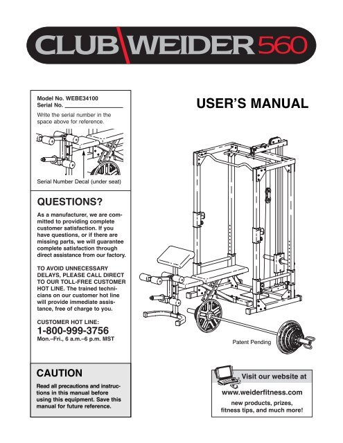
Model No. WEBE34100<br />
Serial No.<br />
Write the serial number in the<br />
space above for reference.<br />
USERÕS MANUAL<br />
Serial Number Decal (under seat)<br />
QUESTIONS<br />
As a manufacturer, we are committed<br />
to providing complete<br />
customer satisfaction. If you<br />
have questions, or if there are<br />
missing parts, we will guarantee<br />
complete satisfaction through<br />
direct assistance from our factory.<br />
TO AVOID UNNECESSARY<br />
DELAYS, PLEASE CALL DIRECT<br />
TO OUR TOLL-FREE CUSTOMER<br />
HOT LINE. The trained technicians<br />
on our customer hot line<br />
will provide immediate assistance,<br />
free of charge to you.<br />
CUSTOMER HOT LINE:<br />
1-800-999-3756<br />
Mon.ÐFri., 6 a.m.Ð6 p.m. MST<br />
Patent Pending<br />
CAUTION<br />
Read all precautions and instructions<br />
in this manual before<br />
using this equipment. Save this<br />
manual for future reference.<br />
Visit our website at<br />
www.<strong>weider</strong>fitness.com<br />
new products, prizes,<br />
fitness tips, and much more!
Table of Contents<br />
Warning Decal Placement . . . . . . . . . . . . . . . . . . . . . . . . . . . . . . . . . . . . . . . . . . . . . . . . . . . . . . . . . . . . . . . . 2<br />
Important Precautions . . . . . . . . . . . . . . . . . . . . . . . . . . . . . . . . . . . . . . . . . . . . . . . . . . . . . . . . . . . . . . . . . . . 3<br />
Before You Begin . . . . . . . . . . . . . . . . . . . . . . . . . . . . . . . . . . . . . . . . . . . . . . . . . . . . . . . . . . . . . . . . . . . . . . 4<br />
Part Identification Chart . . . . . . . . . . . . . . . . . . . . . . . . . . . . . . . . . . . . . . . . . . . . . . . . . . . . . . . . . . . . . . . . . . 5<br />
Assembly . . . . . . . . . . . . . . . . . . . . . . . . . . . . . . . . . . . . . . . . . . . . . . . . . . . . . . . . . . . . . . . . . . . . . . . . . . . . 6<br />
Adjusting the Weight Bench . . . . . . . . . . . . . . . . . . . . . . . . . . . . . . . . . . . . . . . . . . . . . . . . . . . . . . . . . . . . . . 14<br />
Exercise Guidelines . . . . . . . . . . . . . . . . . . . . . . . . . . . . . . . . . . . . . . . . . . . . . . . . . . . . . . . . . . . . . . . . . . . 17<br />
Muscle Chart . . . . . . . . . . . . . . . . . . . . . . . . . . . . . . . . . . . . . . . . . . . . . . . . . . . . . . . . . . . . . . . . . . . . . . . . . 18<br />
Ordering Replacement Parts . . . . . . . . . . . . . . . . . . . . . . . . . . . . . . . . . . . . . . . . . . . . . . . . . . . . . .Back Cover<br />
Limited Warranty . . . . . . . . . . . . . . . . . . . . . . . . . . . . . . . . . . . . . . . . . . . . . . . . . . . . . . . . . . . . . . . Back Cover<br />
Note: A Part List/Exploded Drawing is attached in the center of this manual. Remove the Part List/Exploded<br />
Drawing before beginning assembly.<br />
Warning Decal Placement<br />
The decals shown at right<br />
have been placed on the<br />
weight bench. If a decal is<br />
missing or illegible, call<br />
our Customer Service<br />
Department toll-free at<br />
1-800-999-3756, Monday<br />
through Friday, 6 a.m. until<br />
6 p.m. Mountain Time, to<br />
order a free replacement<br />
decal. Apply the replacement<br />
decal in the location<br />
shown.<br />
! WARNING<br />
¥ Misuse of this product may result in serious<br />
injury.<br />
¥ Read userÕs manual and follow all warnings<br />
and operating instructions prior to use.<br />
¥ Do not allow children on or around machine.<br />
¥ Replace label if damaged, illegible, or removed.<br />
!<br />
WARNING<br />
¥ Misuse of this<br />
product may result in<br />
serious injury.<br />
¥ Read userÕs manual<br />
and follow all warnings<br />
and operating instructions<br />
prior to use.<br />
¥ Do not allow children<br />
on or around machine.<br />
¥ Replace label if<br />
damaged, illegible,<br />
or removed.<br />
WEIDER is a registered trademark of ICON Health & <strong>Fitness</strong>, Inc.<br />
2
Important Precautions<br />
WARNING: To reduce the risk of serious injury, read the following important precautions<br />
before using the weight bench.<br />
1. Read all instructions in this manual before<br />
using the weight bench. Use the weight<br />
bench only as described in this manual.<br />
2. It is the responsibility of the owner to ensure<br />
that all users of the weight bench are adequately<br />
informed of all precautions.<br />
3. The weight bench is intended for home use<br />
only. Do not use the weight bench in any<br />
commercial, rental, or institutional setting.<br />
4. Use the weight bench only on a level surface.<br />
Cover the floor beneath the weight bench for<br />
protection.<br />
5. Inspect and tighten all parts each time you<br />
use the weight bench. Replace any worn<br />
parts immediately.<br />
6. Keep children under 12 and pets away from<br />
the weight bench at all times.<br />
7. Keep hands and feet away from moving parts.<br />
8. Always wear athletic shoes for foot protection<br />
while exercising.<br />
9. Always make sure there is an equal amount<br />
of weight on each end of the barbell.<br />
10. Always secure the weights with the weight<br />
clips when they are mounted on the barbell<br />
or the weight carriage.<br />
11. The weight bench is designed to support a<br />
maximum of 550 pounds, including the user,<br />
a barbell, and weights. Do not place more<br />
than 300 pounds, including the barbell, on<br />
the weight rests. Do not place more than 150<br />
pounds on the weight carriage. Do not place<br />
more than 150 pounds on the leg lever for<br />
normal use.<br />
12. Make sure that the cables remain on the pulleys<br />
at all times. If the cables bind as you are<br />
exercising, stop immediately and make sure<br />
that the cables are on the pulleys.<br />
13. Always set both weight rests and both<br />
weight spotters at the same height.<br />
14. Always exercise with a partner. When you<br />
are performing bench press exercises, squat<br />
exercises, or toe raise exercises, your partner<br />
should stand behind you to catch the<br />
barbell if you cannot complete a repetition.<br />
15. If you feel pain or dizziness at any time while<br />
exercising, stop immediately and begin cooling<br />
down.<br />
16. Always move the bench out of the way when<br />
performing squat exercises.<br />
17. Always disconnect the lat bar from the<br />
weight bench when performing an exercise<br />
that does not require the lat bar.<br />
WARNING: Before beginning this or any exercise program, consult your physician. This<br />
is especially important for persons over the age of 35 or persons with pre-existing health problems.<br />
Read all instructions before using. ICON assumes no responsibility for personal injury or property<br />
damage sustained by or through the use of this product.<br />
3
Before You Begin<br />
Thank you for selecting the versatile CLUB WEIDER¨<br />
<strong>560</strong> weight bench. The CLUB WEIDER¨ <strong>560</strong> is<br />
designed to help you develop every major muscle<br />
group of the body. Whether your goal is a shapely figure,<br />
dramatic increase in muscle size and strength, or<br />
a healthier cardiovascular system, the CLUB<br />
WEIDER¨ <strong>560</strong> will help you achieve the specific results<br />
you want.<br />
For your benefit, read this manual carefully before<br />
using the CLUB WEIDER¨ <strong>560</strong> weight bench. If you<br />
have additional questions, please call our Customer<br />
Service Department toll-free at 1-800-999-3756,<br />
Monday through Friday, 6 a.m. until 6 p.m. Mountain<br />
Time (excluding holidays). To help us assist you,<br />
please note the product model number and serial<br />
number before calling. The model number is<br />
WEBE34100. The serial number can be found on a<br />
decal attached to the weight bench (see the front<br />
cover of this manual).<br />
Before reading further, please review the drawing<br />
below and familiarize yourself with the parts that are<br />
labeled.<br />
High Pulley Station<br />
Lat Bar<br />
Chin-up Bar<br />
Right Side<br />
Left Side<br />
Weight Rest<br />
Weight Spotter<br />
Weight Carriage<br />
Curl Pad<br />
Seat<br />
Leg Lever<br />
Weight Tube<br />
Weight Tube<br />
Backrest<br />
Low Pulley<br />
Station<br />
300-lb. Olympic<br />
Weight Set<br />
Note: The terms Òright sideÓ and Òleft sideÓ are determined<br />
relative to a person sitting on the bench; they do not correspond<br />
to right and left on the drawings in the manual.<br />
4
Part Identification ChartÑModel No. WEBE34100 R0700A<br />
10mm Spacer (88)Ð1<br />
M10 Flat Washer (76)Ð16<br />
M8 Flat Washer (75)Ð10<br />
M6 Washer (86)Ð4<br />
M10 x 45mm Bolt (71)Ð3<br />
51mm Spacer (78)Ð1<br />
18mm Spacer (80)Ð4<br />
M10 x 50mm Bolt (91)Ð2<br />
28mm Spacer (79)Ð2<br />
24mm Spacer (77)Ð2<br />
M10 x 58mm Carriage Bolt (84)Ð4<br />
M6 x 16mm Screw (82)Ð6<br />
M10 Nylon Locknut (68)Ð54<br />
M10 x 65mm Bolt (83)Ð3<br />
M6 x 38mm Screw (85)Ð4<br />
M8 Nylon Locknut (69)Ð5<br />
M10 x 66mm Bolt (74)Ð2<br />
M8 x 58mm Bolt (87)Ð1<br />
M10 x 75mm Bolt (73)Ð3<br />
M8 x 72mm Bolt (72)Ð4<br />
M10 x 78mm Bolt (70)Ð36<br />
M10 x 178mm Bolt (81)Ð1<br />
5
Assembly<br />
Make Things Easier for Yourself!<br />
Everything in this manual is designed to ensure<br />
that the weight bench can be assembled successfully<br />
by anyone. However, it is important to<br />
realize that the versatile weight bench has many<br />
parts and that the assembly process will take<br />
time. Most people find that by setting aside plenty<br />
of time, assembly will go smoothly.<br />
Before beginning assembly, carefully read the<br />
following information and instructions:<br />
¥ Assembly requires two people.<br />
¥ Place all parts in a cleared area and remove the<br />
packing materials. Do not dispose of the packing<br />
materials until assembly is completed.<br />
¥ Tighten all parts as you assemble them, unless<br />
instructed to do otherwise.<br />
¥ As you assemble the weight bench, make sure all<br />
parts are oriented as shown in the drawings.<br />
¥ For help identifying small parts, use the PART<br />
IDENTIFICATION CHART on page 5.<br />
The following tools (not included) are required<br />
for assembly:<br />
¥ Two adjustable wrenches<br />
¥ One rubber mallet<br />
¥ One standard screwdriver<br />
¥ One Phillips screwdriver<br />
¥ Lubricant, such as grease or petroleum jelly,<br />
and soapy water.<br />
Assembly will be more convenient if you have a<br />
socket set, a set of open-end or closed-end<br />
wrenches, or a set of ratchet wrenches.<br />
1. Before beginning assembly, make sure you<br />
understand the information in the box above.<br />
Important: Some of the parts described in the<br />
assembly steps may be pre-assembled.<br />
Press a 50mm Square Outer Cap (63) onto each<br />
end of the ÒUÓ Base (33).<br />
1<br />
33<br />
68<br />
30<br />
Attach the Bench Leg (30) to the ÒUÓ Base (33)<br />
using two M10 x 58mm Carriage Bolts (84) and two<br />
M10 Nylon Locknuts (68).<br />
68<br />
63<br />
84<br />
2. Attach the Bench Frame (26) to the Bench Leg (30)<br />
using two M10 x 65mm Bolts (83), two M10 Flat<br />
Washers (76), and two M10 Nylon Locknuts (68).<br />
2<br />
83<br />
76<br />
68<br />
83<br />
26<br />
30<br />
76<br />
6
3. Press a 51mm x 76mm Outer Cap (62) onto each<br />
end of the Bench Base (34).<br />
3<br />
26<br />
68<br />
Attach the Bench Base (34) to the Bench Frame<br />
(26) using two M10 x 58mm Carriage Bolts (84) and<br />
two M10 Nylon Locknuts (68).<br />
62<br />
34<br />
84<br />
62<br />
4. Press three 45mm Square inner Caps (61) into the<br />
Leg Lever (31). Press a 1Ó Round Inner Cap (65)<br />
into the indicated end of the Weight Tube (32).<br />
Insert the Weight Tube into the Leg Lever (31) and<br />
press an Angled Cap (66) onto the other end of the<br />
Weight Tube. Secure the Weight Tube using an M8<br />
x 58mm Bolt (87), two M8 Flat Washers (75), a<br />
10mm Spacer (88), and an M8 Nylon Locknut (69).<br />
4<br />
37<br />
36<br />
61<br />
37<br />
87<br />
61<br />
88<br />
68<br />
31<br />
66<br />
30<br />
83<br />
Press two Weight Adapter Bushings (37) into the<br />
ends of the Weight Adapter (36). Slide the Weight<br />
Adapter onto the Weight Tube (32) and secure it<br />
with the Weight Adapter Pin (67).<br />
65<br />
67<br />
75<br />
32<br />
61<br />
69<br />
Lubricate an M10 x 65mm Bolt (83). Attach the Leg<br />
Lever (31) to the bracket on the Bench Leg (30)<br />
with the Bolt and an M10 Nylon Locknut (68). Do<br />
not overtighten the Nylon Locknut; the Leg<br />
Lever must pivot freely.<br />
5<br />
Wide End<br />
25<br />
5. Press the four 1Ó Square Inner Caps (58) into the<br />
ends of the Right and Left Backrest Frames (23,<br />
24). Press the two 1Ó x 2Ó Inner Caps (59) into the<br />
adjustment tubes of the Backrest Frames.<br />
23<br />
58<br />
85<br />
58 58<br />
86<br />
86<br />
Attach the Backrest (25) to the Backrest Frames<br />
(23, 24) with four M6 x 38mm Screws (85) and four<br />
M6 Washers (86). The Backrest Frames and the<br />
Backrest must be oriented as shown.<br />
86<br />
85<br />
59<br />
58<br />
86<br />
85<br />
59<br />
24<br />
85<br />
6. Lubricate the M10 x 178mm Bolt (81). Attach the<br />
Backrest Frames (23, 24) to the Bench Frame (26)<br />
with the Bolt, two M10 Flat Washers (76), and an<br />
M10 Nylon Locknut (68).<br />
6<br />
25<br />
Secure the Backrest (25) at the desired height by<br />
inserting the Backrest Pin (40) through one of the<br />
sets of holes in the Backrest Frames (23, 24) and<br />
through the hole in the Bench Frame (26).<br />
Make sure the Backrest Pin is completely inserted<br />
through both Backrest Frames.<br />
81<br />
76<br />
23<br />
24<br />
26<br />
76 68<br />
40<br />
7
7. With the wide end of the Seat (27) positioned as<br />
shown, attach the Seat to the brackets on the<br />
Bench Frame (26) using four M6 x 16mm Screws<br />
(82).<br />
7<br />
Wide End<br />
27<br />
26<br />
82<br />
9. Attach the Curl Pad (29) to the Curl Post (28) with<br />
two M6 x 16mm Screws (82).<br />
Slide the Curl Post (28) into the Bench Leg (30).<br />
Align one of the adjustment holes in the Curl Post<br />
with the adjustment hole in the Bench Leg. Tighten<br />
the Curl Post Adjustment Knob (90) into the holes<br />
in the Curl Post and the Bench Leg. Make sure you<br />
fully tighten the Curl Post Adjustment Knob.<br />
10. Press 60mm Square Outer Caps (56) onto the ends<br />
of the Right and Left Bases (1, 3).<br />
10<br />
56<br />
Attach the Right and Left Bases (1, 3) to the Center<br />
Base (2) using four M10 x 78mm Bolts (70) and<br />
four M10 Nylon Locknuts (68). Do not tighten the<br />
Nylon Locknuts yet.<br />
1<br />
70<br />
68<br />
2<br />
68<br />
56<br />
56<br />
70<br />
56<br />
3<br />
8
11. Identify the two Rear Uprights (8), which are slightly<br />
shorter than the Front Uprights (not shown).<br />
Attach the Rear Uprights (8) to the Left and Right<br />
Bases (1, 3) using four M10 x 78mm Bolts (70) and<br />
four M10 Nylon Locknuts (68). Do not tighten the<br />
Nylon Locknuts yet. Make sure the Uprights are<br />
oriented exactly as shown, with the adjustment<br />
holes on the indicated side near the bottom.<br />
Press a 60mm Square Outer Cap (56) onto the end<br />
of the Weight Guide Base (4).<br />
11<br />
1<br />
70<br />
8<br />
68<br />
2<br />
Adjustment<br />
Holes<br />
68<br />
4<br />
8<br />
56<br />
Orient the Foot Plate (5) and the Weight Guide<br />
Base (4) as shown. Attach the Foot Plate and the<br />
Weight Guide Base to the Center Base (2) using<br />
two M10 x 78mm Bolts (70) and two M10 Nylon<br />
Locknuts (68). Do not tighten the Nylon Locknuts<br />
yet.<br />
70<br />
5<br />
68<br />
3<br />
12. Attach one of the Front Uprights (7) and two Joint<br />
Plates (6) to the Left Base (3) using four M10 x<br />
78mm Bolts (70) and four M10 Nylon Locknuts (68).<br />
Make sure the Front Upright is oriented so that<br />
the holes on the bottom of the Front Upright<br />
and the holes in the Joint Plates line up. If they<br />
do not line up, turn the Front Upright upsidedown.<br />
Do not tighten the Nylon Locknuts yet.<br />
Make sure the Front Upright is turned so the<br />
adjustment holes are facing the Rear Upright<br />
(8).<br />
12<br />
1<br />
57<br />
7<br />
8<br />
Attach the other Front Upright (7, not shown) and<br />
two Joint Plates (6, not shown) to the Right Base<br />
(1) in the same manner.<br />
70<br />
68<br />
Tap a 60mm Square Inner Cap (57) into each of the<br />
Front Uprights (7).<br />
6<br />
3<br />
13. Refer to drawing 13a. Press Square Bushings (21)<br />
into one of the Weight Rests (19) and one of the<br />
Weight Spotters (20) as shown. Pull out the<br />
Adjustment Knobs (22) and slide the Weight Spotter<br />
and the Weight Rest down over the right Uprights<br />
(7, 8) as indicated.<br />
Refer to drawing 13b. Secure the Weight Spotter<br />
(20) and the Weight Rest (19) to the right Uprights<br />
(7, 8) by tightening each of the three Adjustment<br />
Knobs (22) into one of the adjustment holes in the<br />
Uprights.<br />
Assemble the other Weight Spotter (20) and Weight<br />
Rest (19) to the left Uprights (7, 8) in the same<br />
manner. Make sure both Weight Spotters and<br />
both Weight Rests are at the same height.<br />
9<br />
6<br />
13a<br />
13b<br />
21<br />
19 22<br />
21<br />
19<br />
20<br />
22<br />
20<br />
21<br />
8<br />
7<br />
68<br />
8<br />
7<br />
22<br />
22
14. Attach the Chin-up Bar (13) and two Joint Plates (6)<br />
to the Front Uprights (7) using four M10 x 78mm<br />
Bolts (70) and four M10 Nylon Locknuts (68). Do<br />
not tighten the Nylon Locknuts yet.<br />
14<br />
6<br />
70<br />
68<br />
13<br />
6<br />
7<br />
68<br />
7<br />
70<br />
15. Press a 60mm Square Inner Cap (57) into the Left<br />
Frame (12). Attach the Left Frame to the left<br />
Uprights (7, 8) using four M10 x 78mm Bolts (70)<br />
and four M10 Nylon Locknuts (68). Do not tighten<br />
the Nylon Locknuts yet.<br />
Assemble the Right Frame (10) to the right Uprights<br />
(7, 8) in the same manner.<br />
Attach the Center Frame (11) to the Left Frame (12)<br />
and the Right Frame (10) using four M10 x 78mm<br />
Bolts (70) and four M10 Nylon Locknuts (68).<br />
Tighten all Nylon Locknuts used in steps 10Ð15.<br />
15<br />
10<br />
7<br />
70<br />
68<br />
8<br />
70<br />
7<br />
12<br />
11<br />
70<br />
70<br />
68<br />
68<br />
57<br />
68<br />
8<br />
16. Press the two 51mm Round Inner Caps (89) into<br />
the weight tubes on the Weight Carriage (15).<br />
16<br />
89<br />
16<br />
Press the two Carriage Bushings (16) into the<br />
Weight Carriage (15). Make sure the Weight<br />
Carriage is turned so the weight tubes are near<br />
the top, as shown. Attach the lower Carriage<br />
Bushing using an M10 x 66mm Bolt (74), two M10<br />
Flat Washers (76), the 51mm Spacer (78), and an<br />
M10 Nylon Locknut (68).<br />
68<br />
76<br />
16<br />
78<br />
15<br />
76<br />
Weight Tube<br />
74<br />
89<br />
17. Set the two Weight Bumpers (18) over the indicated<br />
holes in the Weight Guide Base (4). Hold the<br />
Weight Carriage (15) on top of the Weight<br />
Bumpers.<br />
17<br />
9<br />
Insert the two Weight Guides (9) into the Weight<br />
Carriage (15), the Weight Bumpers (18), and the<br />
Weight Guide Base (4). Attach the Weight Guides<br />
using two M8 x 72mm Bolts (72), four M8 Flat<br />
Washers (75), and two M8 Nylon Locknuts (69).<br />
69<br />
15<br />
18<br />
4<br />
75<br />
72<br />
10
18. Press a 60mm Square Inner Cap (57) into the end<br />
of the Weight Guide Frame (14).<br />
18<br />
69<br />
75<br />
57<br />
Hold the Weight Guide Frame (14) on top of the<br />
Center Frame (11) and the Weight Guides (9).<br />
Attach the Weight Guides to the Weight Guide<br />
Frame using two M8 x 72mm Bolts (72), four M8<br />
Flat Washers (75), and two M8 Nylon Locknuts (69).<br />
14<br />
70<br />
75<br />
72<br />
Attach the Weight Guide Frame (14) to the Center<br />
Frame (11) using two M10 x 78mm Bolts (70), two<br />
M10 Flat Washers (76), and two M10 Nylon<br />
Locknuts (68).<br />
76<br />
68<br />
11<br />
9<br />
19. Locate the High Cable (54), which is the longer of<br />
the two Cables. Notice that there is a ball on one<br />
end of the High Cable and a metal sleeve on the<br />
other end.<br />
19<br />
14<br />
Route the metal-sleeve end of the High Cable (54)<br />
up under the lat bar rest on the Weight Guide<br />
Frame (14), down through the indicated hole, back<br />
up through the next hole, and then down through<br />
the hole between the Weight Guides (9) as shown.<br />
Lat Bar<br />
Rest<br />
54<br />
9<br />
20. Insert the end of the High Cable (54) into the hole<br />
in the center of the Weight Carriage (15). Attach the<br />
High Cable using an M10 x 66mm Bolt (74), two<br />
M10 Flat Washers (76), two 24mm Spacers (77),<br />
and an M10 Nylon Locknut (68).<br />
20<br />
68<br />
76<br />
77<br />
54<br />
77<br />
76<br />
15<br />
74<br />
21. Lift the High Cable (54) in the location shown.<br />
Attach two Pulleys (53) inside the bracket on the<br />
Weight Guide Frame (14) using two M10 x 50mm<br />
Bolts (91) and two M10 Nylon Locknuts (68).<br />
21<br />
68<br />
53<br />
54<br />
14<br />
91<br />
11
22. Lift the High Cable (54) in the location shown.<br />
Attach two Pulleys (53) inside the Weight Guide<br />
Frame (14) using two M10 x 75mm Bolts (73), four<br />
M10 Flat Washers (76), four 18mm Spacers (80),<br />
and two M10 Nylon Locknuts (68).<br />
22<br />
68<br />
76<br />
80<br />
53<br />
54<br />
14<br />
76<br />
80<br />
80<br />
76<br />
80<br />
76<br />
73<br />
23. Pull the High Cable (54) down in the indicated location,<br />
so there is no slack at the ends of the High<br />
Cable.<br />
23<br />
Locate the Low Cable (55). Insert the metal-sleeve<br />
end of the Low Cable into the indicated hole in the<br />
Weight Guide Base (4). Attach the Low Cable using<br />
an M10 x 75mm Bolt (73), two M10 Flat Washers<br />
(76), two 28mm Spacers (79), and an M10 Nylon<br />
Locknut (68).<br />
54<br />
Route the ball-end of the Low Cable (55) through<br />
the bracket on the Center Base (2). Attach a Pulley<br />
inside the bracket using an M10 x 45mm Bolt (71)<br />
and an M10 Nylon Locknut (68).<br />
55<br />
53<br />
76 79<br />
68<br />
2<br />
71<br />
79<br />
4<br />
76<br />
73<br />
24. Hold a Pulley (53) in the High Cable (54) as shown.<br />
Attach a Cable Trap (52) and the two Pulley Plates<br />
(17) to the Pulley using an M10 x 45mm Bolt (71)<br />
and an M10 Nylon Locknut (68).<br />
Lay the Low Cable (55) over a Pulley (53) as<br />
shown. Attach the Pulley and a Cable Trap (52) to<br />
the Pulley Plates (17) using an M10 x 45mm Bolt<br />
(71) and an M10 Nylon Locknut (68). Make sure<br />
the Bolts are inserted through the highest and<br />
lowest holes in the Pulley Plates. In addition,<br />
make sure the Cables are between the Cable<br />
Traps and the Pulleys.<br />
24<br />
68<br />
54<br />
55<br />
17<br />
53<br />
52<br />
17<br />
52<br />
71<br />
12
25. Wet the ends of the Lat Bar (38) with a small<br />
amount of soapy water. Slide the Handgrips (60)<br />
onto the ends of the Lat Bar.<br />
25<br />
60<br />
38<br />
60<br />
26. Make sure all parts of the weight bench are properly tightened. In addition, pull each cable a few<br />
times to make sure the cables move smoothly over the pulleys. If the cables do not move smoothly,<br />
locate and correct the problem. When weights are used, the cables may be damaged if they are<br />
incorrectly routed.<br />
The use of all remaining parts will be explained in ADJUSTING THE WEIGHT BENCH, beginning on page 14.<br />
13
Adjusting the Weight Bench<br />
This section explains how to adjust the weight bench. See the Exercise Guidelines on page 17 for important<br />
information about how to get the most benefit from your exercise program. Also, refer to the accompanying exercise<br />
poster to see the correct form for each exercise.<br />
Inspect and tighten all parts each time you use the weight bench. Replace any worn parts immediately. The<br />
weight bench can be cleaned with a damp cloth and a mild, non-abrasive detergent. Do not use solvents.<br />
USING THE WEIGHT RESTS AND SAFETY<br />
SPOTTERS<br />
Before beginning an exercise, move the Weight Rests<br />
(19) and the Safety Spotters (20) to sets of holes in the<br />
uprights that are best suited for that exercise. The<br />
selected holes for the Safety Spotters should represent<br />
the lowest point to which you want the barbell to go during<br />
the exercise. The selected holes for the Weight<br />
Rests should be at a comfortable height for lifting and<br />
replacing the barbell. Perform the exercise as shown in<br />
the accompanying Exercise Guide. Note: Make sure<br />
the Adjustment Knobs (22) are fully tightened.<br />
19<br />
22<br />
20<br />
WARNING: Always set both Weight<br />
Rests (19) at the same height and both Safety<br />
Spotters (20) at the same height.<br />
SETTING UP THE BENCH FOR SQUAT EXERCISES<br />
Squat exercises should be performed inside the rack<br />
(behind the dotted line in the picture). When performing<br />
squat exercises, set the Weight Rests (19) and the<br />
Safety Spotters (20) at a comfortable height, and move<br />
the bench away from the rack.<br />
WARNING: Always move the bench<br />
when you are performing squat exercises inside<br />
the rack.<br />
19<br />
20<br />
19 20<br />
Squat<br />
Area<br />
14
ADJUSTING THE BACKREST<br />
The Backrest (25) can be used in a decline position, a<br />
level position, or either of two incline positions. To<br />
adjust the Backrest to the decline position, remove the<br />
Adjustment Pin (40) and insert it through the top set of<br />
holes in the Backrest Frames (23, 24).<br />
25<br />
To adjust the Backrest (25) to the level position, insert<br />
the Adjustment Pin (40) through the second set of holes<br />
in the Backrest Frames (23, 24).<br />
To adjust the Backrest (25) to an incline position, insert<br />
the Adjustment Pin (40) through one of the lower two<br />
sets of holes in the Backrest Frames (23, 24).<br />
23<br />
24<br />
40<br />
26<br />
WARNING: When adjusting the position<br />
of the Backrest (25), make sure that the<br />
Adjustment Pin (40) is fully inserted through both<br />
Backrest Frames (23, 24) and the holes in the<br />
Bench Frame (26).<br />
ATTACHING WEIGHTS TO THE LEG LEVER<br />
31<br />
To use the Leg Lever (31), slide the desired amount of<br />
weight onto the Weight Adapter (36).<br />
36<br />
WARNING: Do not place more than<br />
150 pounds on the Leg Lever (31).<br />
ATTACHING WEIGHTS TO THE WEIGHT CARRIAGE<br />
OR THE BARBELL<br />
To use the high or low pulley station, slide the desired<br />
amount of weight onto the weight tubes of the Weight<br />
Carriage (15) and secure the weights with Weight Clips<br />
(43). To use the Barbell (42, not shown), slide the<br />
desired amount of weight onto each side of the Barbell<br />
and secure both sides with a Weight Clip (43).<br />
Weight<br />
Tube<br />
Weight<br />
Tube<br />
15<br />
WARNING: Do not place more than<br />
150 pounds on the Weight Carriage (15). Always<br />
place the same amount of weight on each side of<br />
the Weight Carriage and on each side of the<br />
Barbell (42, not shown). Always secure the<br />
weights on the Weight Carriage and the Barbell<br />
with the Weight Clips (43).<br />
43<br />
15
ATTACHING THE LAT BAR TO THE HIGH PULLEY<br />
STATION OR THE LOW PULLEY STATION<br />
54<br />
To use the high pulley station or the low pulley station,<br />
first place the desired weights on the weight carriage<br />
(see ATTACHING WEIGHTS TO THE WEIGHT CAR-<br />
RIAGE OR THE BARBELL on page 15). Next, attach<br />
the Lat Bar (38) to the High Cable (54) or the Low<br />
Cable (not shown) with a Cable Clip (51).<br />
WARNING: Always disconnect the<br />
Lat Bar (38) when performing an exercise that<br />
does not require using the Lat Bar.<br />
51<br />
38<br />
REMOVING THE CURL POST<br />
When the Curl Post (28) is not in use, it should be<br />
stored away from the weight bench so as not to interfere<br />
with other exercises. To remove the Curl Post,<br />
loosen the Curl Post Adjustment Knob (90) and slide<br />
the Curl Post out of the Bench Leg (30).<br />
28<br />
30<br />
90<br />
REMOVING THE PAD TUBE<br />
For certain exercises, the indicated Pad Tube (35) and<br />
Foam Pads (41) must be removed. To do this, first slide<br />
one of the Foam Pads off the Pad Tube, then pull the<br />
Pad Tube out of the indicated hole in the Bench Leg<br />
(30).<br />
41<br />
30<br />
35<br />
41<br />
TIGHTENING THE CABLES<br />
Woven cable, the type of cable used on the weight<br />
bench, can stretch slightly after it is first used. If there is<br />
slack in the cables, tighten them as described below.<br />
Remove the M10 x 45mm Bolt (71) and the M10 Nylon<br />
Locknut (68) attaching the lower Pulley (53) and Cable<br />
Trap (52) to the two Pulley Plates (17). Reattach the<br />
lower Pulley and Cable Trap to the higher holes in the<br />
Pulley Plates using the Bolt and Nylon Locknut.<br />
If moving just the lower Pulley (53) does not sufficiently<br />
tighten the cables, you can also move the upper Pulley<br />
down one set of holes in the Pulley Plates (17).<br />
68<br />
17<br />
53<br />
52<br />
17<br />
52<br />
71<br />
16
Exercise Guidelines<br />
THE FOUR BASIC TYPES OF WORKOUTS<br />
Muscle Building<br />
The only way to increase the size and strength of<br />
your muscles is to push them close to their maximum<br />
capacity. When you progressively increase the intensity<br />
of your exercise, your muscles will continually<br />
adapt and grow. You can tailor the individual exercise<br />
to the proper intensity level in two ways:<br />
¥ by changing the amount of weight used<br />
¥ by changing the number of repetitions or sets performed<br />
(A ÒrepetitionÓ is one complete cycle of an<br />
exercise, such as one sit-up. A ÒsetÓ is a series of<br />
repetitions).<br />
The proper amount of weight for each exercise obviously<br />
depends upon the individual user. You must<br />
gauge your limits and select the amount of weight that<br />
is right for you. Begin with 3 sets of 8 repetitions for<br />
each exercise you perform. Rest for 3 minutes after<br />
each set. When you can complete 3 sets of 12 repetitions<br />
without difficulty, increase the amount of weight.<br />
Toning<br />
You can tone your muscles by pushing them to a<br />
moderate percentage of their capacity. Select a moderate<br />
amount of weight and increase the number of<br />
repetitions in each set. Complete as many sets of 15<br />
to 20 repetitions as possible without discomfort. Rest<br />
for 1 minute after each set. Work your muscles by<br />
completing more sets rather than by using high<br />
amounts of weight.<br />
Weight Loss<br />
To lose weight, use a low amount of weight and<br />
increase the number of repetitions in each set.<br />
Exercise for 20 to 30 minutes, resting for a maximum<br />
of 30 seconds between sets.<br />
Cross Training<br />
Many people desire a complete and balanced fitness<br />
program. Cross training is an efficient way to accomplish<br />
this. One example of a balanced program is:<br />
¥ Plan weight training workouts on Monday,<br />
Wednesday, and Friday.<br />
¥ Plan 20 to 30 minutes of aerobic exercise, such as<br />
cycling, running, or swimming on Tuesday and<br />
Thursday.<br />
¥ Rest from both weight training and aerobic exercise<br />
for at least one full day each week to give your body<br />
time to regenerate.<br />
The combination of weight training and aerobic exercise<br />
will reshape and strengthen your body and develop<br />
your heart and lungs.<br />
PERSONALIZING YOUR EXERCISE PROGRAM<br />
Specifying the exact length of time for each workout,<br />
as well as the number of repetitions or sets for each<br />
exercise, is a highly individual matter. It is very important<br />
to avoid overdoing it during the first few months<br />
of your exercise program. You should progress at<br />
your own pace and be sensitive to your bodyÕs signals.<br />
If you experience pain or dizziness at any time<br />
while exercising, stop immediately and begin cooling<br />
down. Find out what is wrong before continuing.<br />
Remember that adequate rest and a proper diet are<br />
important factors in any exercise program.<br />
WARMING UP<br />
Begin each workout with 5 to 10 minutes of stretching<br />
and light exercise to warm up. Warming up prepares<br />
your body for more strenuous exercise by increasing<br />
circulation, raising your body temperature and delivering<br />
more oxygen to your muscles.<br />
WORKING OUT<br />
Each workout should include 6 to 10 different exercises.<br />
Select exercises for every major muscle group<br />
with emphasis on the areas that you want to develop<br />
the most. To give balance and variety to your workouts,<br />
vary the exercises from session to session.<br />
Schedule your workouts for the time of day when your<br />
energy level is the highest. Each workout should be<br />
followed by at least one day of rest. Once you find the<br />
schedule that is right for you, stick with it.<br />
EXERCISE FORM<br />
You will gain the greatest benefits from exercising by<br />
maintaining proper form. This requires moving<br />
through the full range of motion for each exercise and<br />
moving only the appropriate parts of the body.<br />
Exercising in an uncontrolled manner will leave you<br />
feeling exhausted. On the exercise poster accompanying<br />
this manual, you will find photographs showing<br />
the correct form for several exercises. A description of<br />
each exercise is also provided, along with a list of the<br />
muscles affected. Refer to the muscle chart on page<br />
18 to find the locations of the muscles.<br />
The repetitions in each set should be performed<br />
smoothly and without pausing. The exertion stage of<br />
each repetition should last about half as long as the<br />
return stage. Proper breathing is important. Exhale<br />
during the exertion stage of each repetition and inhale<br />
during the return stroke. Never hold your breath!<br />
17
Make sure to rest for a short period of time after each<br />
set. The ideal resting periods are:<br />
¥ Rest three minutes after each set for a muscle building<br />
workout.<br />
¥ Rest one minute after each set for a toning workout.<br />
¥ Rest 30 seconds after each set for a weight loss<br />
workout.<br />
Plan to spend the first couple of weeks familiarizing<br />
yourself with the equipment and learning the proper<br />
form for each exercise.<br />
COOLING DOWN<br />
End each workout with 5 to 10 minutes of stretching.<br />
Include stretches for both your arms and legs. Move<br />
slowly as you stretch and do not bounce. Ease into<br />
each stretch gradually and go only as far as you can<br />
without strain. Stretching at the end of each workout<br />
is very effective for increasing flexibility.<br />
STAYING MOTIVATED<br />
For motivation, keep a record of each workout. The<br />
chart on page 19 of this manual can be photocopied<br />
and used to schedule and record your workouts. List<br />
the date, the exercises performed, the weight plus the<br />
numbers of sets and repetitions completed. Record<br />
your weight and key body measurements at the end<br />
of every month.<br />
Remember, the key to achieving the greatest results<br />
is to make exercise a regular and enjoyable part of<br />
your everyday life.<br />
MUSCLE CHART<br />
Trapezius<br />
Deltoid<br />
Biceps<br />
Brachioradials<br />
Abductor<br />
Hip Flexors<br />
Quadriceps<br />
Adductor<br />
Soleus<br />
Pectoralis<br />
Major<br />
Rectus<br />
Abdominus<br />
Obliques<br />
Gluteus<br />
Medius<br />
Trapezius<br />
Deltoid<br />
Rhomboideus<br />
Triceps<br />
Latissimus Dorsi<br />
Spinae Erectors<br />
Brachioradials<br />
Gluteus<br />
Maximus<br />
Abductors<br />
Hamstring<br />
Gastrocnemius<br />
18
MONDAY<br />
Date:<br />
/ /<br />
EXERCISE WEIGHT SETS REPS<br />
TUESDAY<br />
Date:<br />
/ /<br />
WEDNESDAY<br />
Date:<br />
/ /<br />
AEROBIC EXERCISE<br />
EXERCISE WEIGHT SETS REPS<br />
THURSDAY<br />
Date:<br />
/ /<br />
AEROBIC EXERCISE<br />
FRIDAY<br />
Date:<br />
/ /<br />
EXERCISE WEIGHT SETS REPS<br />
Make photocopies of this page for scheduling and recording your workouts.<br />
19
Ordering Replacement Parts<br />
To order replacement parts, simply call our Customer Service Department toll-free at 1-800-999-3756, Monday<br />
through Friday, 6 a.m. until 6 p.m. Mountain Time (excluding holidays). To help us assist you, please be prepared<br />
to give the following information when calling:<br />
¥ The MODEL NUMBER of the product (WEBE34100)<br />
¥ The NAME of the product (CLUB WEIDER¨ <strong>560</strong> weight bench)<br />
¥ The SERIAL NUMBER of the product (see the front cover of this manual)<br />
¥ The KEY NUMBER and DESCRIPTION of the desired part(s) (see the PART LIST and the EXPLODED<br />
DRAWING at the center of this manual).<br />
Limited Warranty<br />
ICON Health & <strong>Fitness</strong>, Inc. (ICON), warrants this product to be free from defects in workmanship and material,<br />
under normal use and service conditions, for a period of ninety (90) days from the date of purchase. This<br />
warranty extends only to the original purchaser. ICON's obligation under this warranty is limited to replacing<br />
or repairing, at ICON's option, the product at one of its authorized service centers. All products for which warranty<br />
claim is made must be received by ICON at one of its authorized service centers with all freight and other<br />
transportation charges prepaid, accompanied by sufficient proof of purchase. All returns must be pre-authorized<br />
by ICON. This warranty does not extend to any product or damage to a product caused by or attributable<br />
to freight damage, abuse, misuse, improper or abnormal usage or repairs not provided by an ICON<br />
authorized service center, products used for commercial or rental purposes, or products used as store display<br />
models. No other warranty beyond that specifically set forth above is authorized by ICON.<br />
ICON is not responsible or liable for indirect, special or consequential damages arising out of or in connection<br />
with the use or performance of the product or damages with respect to any economic loss, loss of property,<br />
loss of revenues or profits, loss of enjoyment or use, costs of removal, installation or other consequential damages<br />
of whatsoever nature. Some states do not allow the exclusion or limitation of incidental or consequential<br />
damages. Accordingly, the above limitation may not apply to you.<br />
The warranty extended hereunder is in lieu of any and all other warranties and any implied warranties of merchantability<br />
or fitness for a particular purpose is limited in its scope and duration to the terms set forth herein.<br />
Some states do not allow limitations on how long an implied warranty lasts. Accordingly, the above limitation<br />
may not apply to you.<br />
This warranty gives you specific legal rights. You may also have other rights which vary from state to state.<br />
ICON HEALTH & FITNESS, INC., 1500 S. 1000 W., LOGAN, UT 84321-9813<br />
Part No. 167767 R0700A<br />
Printed in China © 2000 ICON Health & <strong>Fitness</strong>, Inc.
REMOVE THIS PART LIST/EXPLODED<br />
DRAWING FROM THE MANUAL<br />
SAVE THIS PART LIST/EXPLODED DRAWING FOR FUTURE REFERENCE
Part ListÑModel No. WEBE34100<br />
R0700A<br />
Key No. Qty. Description Key No. Qty. Description<br />
1 1 Right Base<br />
2 1 Center Base<br />
3 1 Left Base<br />
4 1 Weight Guide Base<br />
5 1 Foot Plate<br />
6 6 Joint Plate<br />
7 2 Front Upright<br />
8 2 Rear Upright<br />
9 2 Weight Guide<br />
10 1 Right Frame<br />
11 1 Center Frame<br />
12 1 Left Frame<br />
13 1 Chin-up Bar<br />
14 1 Weight Guide Frame<br />
15 1 Weight Carriage<br />
16 2 Carriage Bushing<br />
17 2 Pulley Plate<br />
18 2 Weight Bumper<br />
19 2 Weight Rest<br />
20 2 Weight Spotter<br />
21 12 Square Bushing<br />
22 6 Adjustment Knob<br />
23 1 Right Backrest Frame<br />
24 1 Left Backrest Frame<br />
25 1 Backrest<br />
26 1 Bench Frame<br />
27 1 Seat<br />
28 1 Curl Post<br />
29 1 Curl Pad<br />
30 1 Bench Leg<br />
31 1 Leg Lever<br />
32 1 Weight Tube<br />
33 1 ÒUÓ Base<br />
34 1 Bench Base<br />
35 3 Pad Tube<br />
36 1 Weight Adapter<br />
37 2 Weight Adapter Bushing<br />
38 1 Lat Bar<br />
39 1 Strap<br />
40 1 Backrest Pin<br />
41 6 Foam Pad<br />
42 1 Weight Bar<br />
43 4 Weight Clip<br />
44 8 Weight Clip Sleeve<br />
45 2 2.5-lb. Weight<br />
46 4 5-lb. Weight<br />
47 2 10-lb. Weight<br />
48 2 25-lb. Weight<br />
49 2 35-lb. Weight<br />
50 2 45-lb. Weight<br />
51 2 Cable Clip<br />
52 2 Cable Trap<br />
53 7 Pulley<br />
54 1 High Cable<br />
55 1 Low Cable<br />
56 5 60mm Square Outer Cap<br />
57 5 60mm Square Inner Cap<br />
58 4 1Ó Square Inner Cap<br />
59 2 1Ó x 2Ó Inner Cap<br />
60 2 Handgrip<br />
61 3 45mm Square Inner Cap<br />
62 2 51mm x 76mm Outer Cap<br />
63 2 50mm Square Outer Cap<br />
64 6 3/4Ó Round Inner Cap<br />
65 1 1Ó Round Inner Cap<br />
66 1 Angled Cap<br />
67 1 Weight Adapter Pin<br />
68 54 M10 Nylon Locknut<br />
69 5 M8 Nylon Locknut<br />
70 36 M10 x 78mm Bolt<br />
71 3 M10 x 45mm Bolt<br />
72 4 M8 x 72mm Bolt<br />
73 3 M10 x 75mm Bolt<br />
74 2 M10 x 66mm Bolt<br />
75 10 M8 Flat Washer<br />
76 16 M10 Flat Washer<br />
77 2 24mm Spacer<br />
78 1 51mm Spacer<br />
79 2 28mm Spacer<br />
80 4 18mm Spacer<br />
81 1 M10 x 178mm Bolt<br />
82 6 M6 x 16mm Screw<br />
83 3 M10 x 65mm Bolt<br />
84 4 M10 x 58mm Carriage Bolt<br />
85 4 M6 x 38mm Screw<br />
86 4 M6 Washer<br />
87 1 M8 x 58mm Bolt<br />
88 1 10mm Spacer<br />
89 2 51mm Round Inner Cap<br />
90 1 Curl Post Adjustment Knob<br />
91 2 M10 x 50mm Bolt<br />
# 1 UserÕs Manual<br />
# 1 Exercise Chart<br />
Note: Ò#Ó indicates a non-illustrated part. Specifications are subject to change without notice. See the back cover<br />
of the userÕs manual for information about ordering replacement parts.