4th International Conference on Principles and Practices ... - MADOC
4th International Conference on Principles and Practices ... - MADOC
4th International Conference on Principles and Practices ... - MADOC

You also want an ePaper? Increase the reach of your titles
YUMPU automatically turns print PDFs into web optimized ePapers that Google loves.
UML sequence diagrams are am<strong>on</strong>g the most widely used<br />
diagrams of the Unified Model Language (UML) [32]. The UML<br />
is now c<strong>on</strong>sidered the lingua franca of software modeling<br />
supporting both structural (static) <strong>and</strong> behavioral (dynamic)<br />
models <strong>and</strong> their representati<strong>on</strong> as diagrams. Behavioral diagrams<br />
include activity, communicati<strong>on</strong>, <strong>and</strong> sequence diagrams. Such<br />
sequence diagrams are a popular form to illustrate participants of<br />
an interacti<strong>on</strong> <strong>and</strong> the messages between these participants. They<br />
are widely used in specificati<strong>on</strong> documents <strong>and</strong> testing activities<br />
[24] as well as in the scientific <strong>and</strong> technical literature <strong>on</strong> software<br />
engineering.<br />
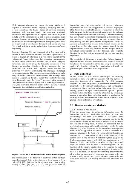
Sequence diagrams [32] are composed of a few basic <strong>and</strong> a<br />
number of more advanced elements. The basic ingredients of a<br />
sequence diagram are illustrated in a very simple example in the<br />
right part of Figure 2 al<strong>on</strong>g with their respective counterparts in<br />
the Java source code <strong>on</strong> the left-h<strong>and</strong> side. In such a diagram<br />
participants are shown al<strong>on</strong>g the horiz<strong>on</strong>tal dimensi<strong>on</strong> of the<br />
diagram as so-called ‘life-lines’. In the example, the two<br />
participants are ‘Editor’ <strong>and</strong> ‘Diagram’. These life-lines are<br />
c<strong>on</strong>nected by arrows symbolizing the messages exchanged<br />
between participants. The messages are ordered chr<strong>on</strong>ologically<br />
al<strong>on</strong>g the vertical dimensi<strong>on</strong>. In the example, two messages from<br />
Editor to Diagram are depicted, namely the c<strong>on</strong>structor message<br />
‘new Diagram()’ <strong>and</strong> the ‘open()’ message. More advanced<br />
c<strong>on</strong>cepts (not shown in the figure) such as modeling alternatives,<br />
loops, <strong>and</strong> c<strong>on</strong>current behavior, can be factored out into so-called<br />
‘fragments’ for modularizati<strong>on</strong> <strong>and</strong> better readability.<br />
Figure 2. Behavior as Java source code <strong>and</strong> sequence diagram<br />
The rec<strong>on</strong>structi<strong>on</strong> of the behavior of a software system has been<br />
studied extensively both in the static case (from source or byte<br />
code) [36], [37], [38] <strong>and</strong> in the dynamic case (from tracing<br />
running systems) [6], [33], [34]. [42] <strong>and</strong> [7] focus more <strong>on</strong><br />
interacti<strong>on</strong> with <strong>and</strong> underst<strong>and</strong>ing of sequence diagrams,<br />
respectively. An overview of approaches is provided by [25] <strong>and</strong><br />
[20]. Despite this c<strong>on</strong>siderable amount of work there is often little<br />
informati<strong>on</strong> <strong>on</strong> implementati<strong>on</strong>-centric questi<strong>on</strong>s or the rati<strong>on</strong>ale<br />
behind implementati<strong>on</strong> decisi<strong>on</strong>s. Our study is intended to remedy<br />
this lack of such a systematic investigati<strong>on</strong> <strong>and</strong> is motivated by<br />
our experiences in implementing our own sequence diagram<br />
reengineering tool. This paper has two main purposes. Firstly, we<br />
describe <strong>and</strong> analyze the possible technological opti<strong>on</strong>s for the<br />
required areas. We also report the less<strong>on</strong>s learned by our<br />
implementati<strong>on</strong>. In this way, the more abstract analysis based <strong>on</strong><br />
theoretical c<strong>on</strong>siderati<strong>on</strong>s <strong>and</strong> the technical <strong>and</strong> scientific<br />
literature is verified <strong>and</strong> complemented by our own practical<br />
experience.<br />
The remainder of this paper is organized as follows. Secti<strong>on</strong> 2<br />
explores methods to collect relevant data <strong>and</strong> secti<strong>on</strong> 3 describes<br />
the choices for representati<strong>on</strong> of this data using a suitable metamodel.<br />
We describe opti<strong>on</strong>s for visualizati<strong>on</strong> <strong>and</strong> model or<br />
graphics export in secti<strong>on</strong> 4 <strong>and</strong> 5, respectively.<br />
2. Data Collecti<strong>on</strong><br />
In this secti<strong>on</strong> we will discuss technologies for retrieving<br />
informati<strong>on</strong> from Java software systems with the purpose of<br />
generating instances of a meta-model for UML sequence<br />
diagrams. We focus <strong>on</strong> dynamic (or executi<strong>on</strong>-time) methods but<br />
cover static (or development-time) methods as well for the sake of<br />
completeness. Static methods gather informati<strong>on</strong> from a n<strong>on</strong>running,<br />
(source or byte) code-represented system. Dynamic<br />
methods <strong>on</strong> the other h<strong>and</strong> record the interacti<strong>on</strong> by observing a<br />
system in executi<strong>on</strong>. Data collecti<strong>on</strong> requires a mechanism for<br />
filtering relevant executi<strong>on</strong>-time events which supports a finegrained<br />
selecti<strong>on</strong> of method invocati<strong>on</strong>s.<br />
2.1 Development-time Methods<br />
2.1.1 Source Code Based<br />
Using the source code for collecting informati<strong>on</strong> about the<br />
interacti<strong>on</strong> within an applicati<strong>on</strong> will have at least <strong>on</strong>e<br />
disadvantage: <strong>on</strong>e must have access to the source code.<br />
Nevertheless source code analysis is a comm<strong>on</strong> practice in the<br />
reverse engineering of software systems <strong>and</strong> supported by most of<br />
the available modeling tools. It should be menti<strong>on</strong>ed that the<br />
analysis of source code will provide satisfactory results for static<br />
diagrams (e.g., class diagrams), but the suitability for the dynamic<br />
behavior of an applicati<strong>on</strong> is limited. If <strong>on</strong>e is interested in a<br />
sequence diagram in the form of a comm<strong>on</strong> forward engineered<br />
diagram (i.e., a visualizati<strong>on</strong> of all possible branches of the<br />
c<strong>on</strong>trol flow in the so-called CombinedFragment [32] of the<br />
UML), source code analysis will fulfill this requirement. In [37]<br />
Rountev, Volgin, <strong>and</strong> Reddoch introduce an algorithm which<br />
maps the c<strong>on</strong>trol flow to these CombinedFragments. If the<br />
intenti<strong>on</strong> of the reverse engineering is to visualize the actual<br />
interacti<strong>on</strong> any approach of static code analysis is doomed to fail,<br />
since it is inherently not possible to completely deduce the state<br />
of a system in executi<strong>on</strong> by examining the source code <strong>on</strong>ly<br />
without actually running the system. Obvious problems include<br />
c<strong>on</strong>diti<strong>on</strong>al behavior, late binding, <strong>and</strong> sensor or interactive user<br />
input.<br />
126