33 70 02 Electrical Distribution System, Underground.pdf - WPC
33 70 02 Electrical Distribution System, Underground.pdf - WPC
33 70 02 Electrical Distribution System, Underground.pdf - WPC

Create successful ePaper yourself
Turn your PDF publications into a flip-book with our unique Google optimized e-Paper software.
JBLM DESIGN STANDARDS<br />
SECTION <strong>33</strong> <strong>70</strong> <strong>02</strong>.00 10 - ELECTRICAL DISTRIBUTION SYSTEM, UNDERGROUND<br />
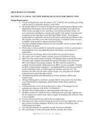
Design Requirements<br />
a. JBLM’ distribution system is a single-point-grounded system operating at 13,800 volts.<br />
JBLM has adopted Tacoma Public Utilities (TPU) design criteria as “industry standards”<br />
for utility construction where such criteria do not conflict with NESC requirements.<br />
Construction details and specifications can be found at TacomaPower.com and may be<br />
utilized in a case by case basis with Public Works permission.<br />
b. <strong>Underground</strong> electrical installations shall be per the National <strong>Electrical</strong> Safety Code<br />
(NESC ANSI C-2), NFPA <strong>70</strong>, and TPU design standards.<br />
c. Cable construction shall be Type MV, with EPR insulation at 1<strong>33</strong>% level.<br />
d. Where primary splicing is required, provide junction assemblies, in an appropriately<br />
sized vault, with a hinged diamond-plate lid. Angle assemblies upward for above-ground<br />
operation. All medium-voltage separable insulated connectors shall be of the loadbreak<br />
type.<br />
e. All transformers shall be set on a vault, with an external man access to the inside of the<br />
vault. Minimum size vault shall be 7’ x 7’ x 6’.<br />
f. All conductors, in any vault, shall be fire-taped or painted. Conductors shall be looped<br />
and racked a minimum of 360 degrees in vaults. Conductors shall be secured to<br />
insulators on racks on all four walls of the vault.<br />
g. All primary duct banks shall consist of a minimum of two 4” conduits for 200-Amp<br />
laterals and 2-5” conduits or larger for conductors of ampacity greater than 200 amps.<br />
Conduits shall be encased in Controlled Density Fill (CDF) except under roads or paved<br />
areas subject to vehicular traffic, with a minimum 1/0 bare copper ground wire embedded<br />
in the encasement for 200 amp and below feeders and laterals and 4/0 bare copper ground<br />
wire for 600 amp feeders and conductors of ampacity greater than 200 amps. When<br />
installing new duct backs or conduits, install a minimum of one spare conduit of the same<br />
size as the conduit being installed. Provide metallic warning tape above ducts and locate<br />
12” below finished grade. Duct banks under roads, paved areas, or railroads subject to<br />
vehicular traffic shall be encased in reinforced concrete. A 24-inch minimum burial<br />
depth is required to the top of the CDF encasement. Maximum depth to the top of<br />
electrical duct banks shall be 30 inches as discussed in the note associated with Figure<br />
310.60 of NFPA <strong>70</strong>.<br />
h. All transformers shall be of the loop-feed type with arrestors on the unused side of the<br />
loop (if applicable).<br />
i. Connections for both primary and secondary conductors shall be of the compression type,<br />
except below-grade ground connections shall be of the exothermic type and pad-mounted<br />
transformer arrestor grounds shall be removable.<br />
j. Transformers shall be new, dead-front, and comply with ANSI C57.12.26. Transformers<br />
shall be equipped with current limiting bayonet oil-immersed fuses, five taps (two above<br />
and two below nominal), and a loadbreak switch to facilitate opening and closing of<br />
either side of the loop, and the ability to de-energize the transformer with the loop<br />
remaining energized. High-voltage warning signs shall be permanently attached to each<br />
side of the transformer. Copper-faced steel or stainless steel ground connection pads<br />
SECTION <strong>33</strong> <strong>70</strong> <strong>02</strong> Page 1
shall be provided in both the high and low-voltage compartments. Dial-type<br />
thermometer, pressure relief valve, liquid-level gauge, and drain valve with built-in<br />
sampling device shall be provided. Insulated-bushing-type parking stands shall be<br />
provided adjacent to each separable load-break elbow to provide for cable isolation.<br />
k. Provide medium-voltage cable test on all new primary conductors.<br />
l. Provide coordination study to demonstrate that the equipment selected and system<br />
constructed meets the contract requirements for equipment ratings, coordination, and<br />
protection. The study shall be performed by a registered professional engineer with<br />
demonstrated experience in power system coordination.<br />
m. Provide detailed as-built drawings.<br />
n. Non-free-breathing electrical equipment containing dielectric fluid shall be furnished<br />
with Natural (Vegetable Oil) Ester Fluid per ASTM D 6871 – 03 (2008) and IEEE<br />
C57.147.<br />
SECTION <strong>33</strong> <strong>70</strong> <strong>02</strong>.00 10<br />
ELECTRICAL DISTRIBUTION SYSTEM, UNDERGROUND<br />
PART 1<br />
GENERAL<br />
1.1 REFERENCES<br />
The publications listed below form a part of this specification to the<br />
extent referenced. The publications are referred to within the text by the<br />
basic designation only.<br />
ALLIANCE FOR TELECOMMUNICATIONS INDUSTRY SOLUTIONS (ATIS)<br />
ATIS O5.1<br />
(20<strong>02</strong>; Supple A 2003; Supple B 2003; Supple C<br />
2004) Specifications and Dimensions (for Wood<br />
Poles)<br />
ASSOCIATION OF EDISON ILLUMINATING COMPANIES (AEIC)<br />
AEIC CS8<br />
(2000) Extruded Dielectric Shielded Power<br />
Cables Rated 5 Through 46 kV<br />
ASTM INTERNATIONAL (ASTM)<br />
ASTM A 123/A 123M<br />
ASTM A 153/A 153M<br />
ASTM A 48/A 48M<br />
ASTM B 117<br />
(2008) Standard Specification for Zinc (Hot-<br />
Dip Galvanized) Coatings on Iron and Steel<br />
Products<br />
(2005) Standard Specification for Zinc<br />
Coating (Hot-Dip) on Iron and Steel Hardware<br />
(2003) Standard Specification for Gray Iron<br />
Castings<br />
(2007a) Standing Practice for Operating Salt<br />
Spray (Fog) Apparatus<br />
SECTION <strong>33</strong> <strong>70</strong> <strong>02</strong> Page 2
ASTM B 3<br />
ASTM B 496<br />
ASTM B 8<br />
ASTM C 478<br />
ASTM C 478M<br />
ASTM D 1654<br />
ASTM D 2472<br />
ASTM D 4059<br />
(2001; R 2007) Standard Specification for<br />
Soft or Annealed Copper Wire<br />
(2004) Standard Specification for Compact<br />
Round Concentric-Lay-Stranded Copper<br />
Conductors<br />
(2004) Standard Specification for Concentric-<br />
Lay-Stranded Copper Conductors, Hard, Medium-<br />
Hard, or Soft<br />
(2008) Standard Specification for Precast<br />
Reinforced Concrete Manhole Sections<br />
(2008e1) Standard Specification for Precast<br />
Reinforced Concrete Manhole Sections (Metric)<br />
(2008) Evaluation of Painted or Coated<br />
Specimens Subjected to Corrosive Environments<br />
(2000; R 2006) Standard Specification for<br />
Sulphur Hexafluoride<br />
(2000; R 2005e1) Analysis of Polychlorinated<br />
Biphenyls in Insulating Liquids by Gas<br />
Chromatography<br />
ASTM D 6871 (2003) Standard Specification for Natural<br />
(Vegetable Oil) Ester Fluids Used in<br />
<strong>Electrical</strong> Apparatus<br />
ASTM D 923<br />
(2007) Standard Practice for Sampling<br />
<strong>Electrical</strong> Insulating Liquids<br />
FM GLOBAL (FM)<br />
FM P7825a<br />
(2005) Approval Guide Fire Protection<br />
INSTITUTE OF ELECTRICAL AND ELECTRONICS ENGINEERS (IEEE)<br />
IEEE C135.30<br />
IEEE C2<br />
IEEE C37.1<br />
IEEE C37.121<br />
IEEE C37.13<br />
(1988) Zinc-Coated Ferrous Ground Rods for<br />
Overhead or <strong>Underground</strong> Line Construction<br />
(2007; Errata 2007; INT 2008) National<br />
<strong>Electrical</strong> Safety Code<br />
(2007) Definition, Specification, and<br />
Analysis of <strong>System</strong>s Used for Supervisory<br />
Control, Data Acquisition, and Automatic<br />
Control<br />
(1989; R 2006) American National Standard for<br />
Switchgear Unit Substations Requirements<br />
(1990; R 1995) Standard for Low-Voltage AC<br />
Power Circuit Breakers Used in Enclosures<br />
SECTION <strong>33</strong> <strong>70</strong> <strong>02</strong> Page 3
IEEE C37.16<br />
IEEE C37.2<br />
IEEE C37.20.1<br />
IEEE C37.20.2<br />
IEEE C37.20.3<br />
IEEE C37.23<br />
IEEE C37.30<br />
IEEE C37.34<br />
IEEE C37.41<br />
IEEE C37.46<br />
IEEE C37.63<br />
IEEE C37.90<br />
IEEE C37.90.1<br />
IEEE C57.12.00<br />
IEEE C57.12.21<br />
(2000) Recommendations for Low-Voltage Power<br />
Circuit Breakers and AC Power Circuit<br />
Protectors, - Preferred Ratings, Related<br />
Requirements, and Application<br />
(1996; R 2001) <strong>Electrical</strong> Power <strong>System</strong> Device<br />
Function Numbers and Contact Designations<br />
(20<strong>02</strong>; Addenda A 2005; Addenda B 2006; R<br />
2007) Standard for Metal-Enclosed Low-Voltage<br />
Power Circuit-Breaker Switchgear<br />
(1999) Metal-Clad Switchgear<br />
(2001; R 2006) Metal-Enclosed Interrupter<br />
Switchgear<br />
(2003) Guide for Metal-Enclosed Bus and<br />
Calculating Losses in Isolated-Phase Bus<br />
(1997) Requirements for High-Voltage Switches<br />
(1994) Test Code for High-Voltage Air<br />
Switches<br />
(2000) Design Tests for High-Voltage Fuses,<br />
<strong>Distribution</strong> Enclosed Single-Pole Air<br />
Switches, Fuse Disconnecting Switches, and<br />
Accessories<br />
(2000) For High Voltage Expulsion and<br />
Current-Limiting Type Power Class Fuses and<br />
Fuse Disconnecting Switches<br />
(2005) Requirements for Overhead, Pad-<br />
Mounted, Dry-Vault, and Submersible Automatic<br />
Line Sectionalizers for AC <strong>System</strong>s<br />
(2005) Standard for Relays and Relay <strong>System</strong>s<br />
Associated With Electric Power Apparatus<br />
(20<strong>02</strong>; Errata 2003) Surge Withstand<br />
Capability (SWC) Tests for Relays and Relay<br />
<strong>System</strong>s Associated with Electric Power<br />
Apparatus<br />
(2006) Standard General Requirements for<br />
Liquid-Immersed <strong>Distribution</strong>, Power, and<br />
Regulating Transformers<br />
(1992) Requirements for Pad-Mounted,<br />
Compartmental-Type, Self-Cooled, Single-Phase<br />
<strong>Distribution</strong> Transformers with High-Voltage<br />
Bushings; High Voltage, 34 500 Grd Y/199200<br />
Volts and Below; Low Voltage, 2400/120 Volts;<br />
167 kVA and Smaller<br />
SECTION <strong>33</strong> <strong>70</strong> <strong>02</strong> Page 4
IEEE C57.12.26<br />
(1992; Addenda 1993) Transformers - Pad-<br />
Mounted Compartmental-Type, Self-Cooled,<br />
Three-Phase <strong>Distribution</strong> Transformers for Use<br />
with Separable Insulated High-Voltage<br />
Connectors, High Voltage, (34 500 Grd Y/19<br />
920 and Below; 2500 kVA and Smaller)<br />
IEEE C57.12.28 (2005) Standard for Pad-Mounted Equipment -<br />
Enclosure Integrity<br />
IEEE C57.13<br />
IEEE C57.98<br />
IEEE C57.147<br />
IEEE C62.11<br />
IEEE Std 386<br />
IEEE Std 404<br />
IEEE Std 48<br />
IEEE Std 81<br />
(2008) Standard Requirements for Instrument<br />
Transformers<br />
(1993; R 1999) Guide for Transformer Impulse<br />
Tests<br />
(2008) Guide for Acceptance and Maintenance<br />
of Natural Ester Fluids in Transformers<br />
(2005; Amendment A 2008) Standard for Metal-<br />
Oxide Surge Arresters for Alternating Current<br />
Power Circuits (>1kV)<br />
(2006) Standard for Separable Insulated<br />
Connector <strong>System</strong>s for Power <strong>Distribution</strong><br />
<strong>System</strong>s Above 600V<br />
(2006) Extruded and Laminated Dielectric<br />
Shielded Cable Joints Rated 2500 V Through<br />
500 000 V<br />
(1996; R 2003) Test Procedures and<br />
Requirements for Alternating-Current Cable<br />
Terminations 2.5 kV through 765 kV<br />
(1983) Guide for Measuring Earth Resistivity,<br />
Ground Impedance, and Earth Surface<br />
Potentials of a Ground <strong>System</strong> (Part 1)Normal<br />
Measurements<br />
INTERNATIONAL ELECTROTECHNICAL COMMISSION (IEC)<br />
IEC 6<strong>02</strong>55-21-3 (1993) <strong>Electrical</strong> Relays - Part 21:<br />
Vibration, Shock, Bump And Seismic Tests On<br />
Measuring Relays And Protection Equipment -<br />
Section 3: Seismic Tests<br />
NATIONAL ELECTRICAL MANUFACTURERS ASSOCIATION (NEMA)<br />
NEMA AB 1<br />
NEMA BU 1.1<br />
(20<strong>02</strong>) Molded-Case Circuit Breakers, Molded<br />
Case Switches, and Circuit-Breaker Enclosures<br />
(2005) General Instructions for Proper<br />
Handling, Installation, Operation, and<br />
Maintenance of Busway Rated 600 Volts or Less<br />
SECTION <strong>33</strong> <strong>70</strong> <strong>02</strong> Page 5
NEMA C119.1<br />
NEMA C12.10<br />
NEMA C12.11<br />
NEMA C12.4<br />
NEMA C29.1<br />
NEMA C37.50<br />
NEMA C80.1<br />
NEMA FB 1<br />
NEMA FU 1<br />
NEMA LA 1<br />
NEMA PB 1<br />
NEMA PB 2<br />
NEMA SG 2<br />
NEMA TC 6 & 8<br />
NEMA TC 7<br />
(2006) Sealed Insulated <strong>Underground</strong> Connector<br />
<strong>System</strong>s Rated 600 Volts<br />
(2004) Physical Aspects of Watthour Meters<br />
(2007) Instrument Transformers for Revenue<br />
Metering, 10 kV BIL through 350 kV BIL (0.6<br />
kV NSV through 69 kV NSV)<br />
(1984; R 20<strong>02</strong>) Mechanical Demand Registers<br />
(1988; R 20<strong>02</strong>) Test Methods for <strong>Electrical</strong><br />
Power Insulators<br />
(1989; R 2000) Low-Voltage AC Power Circuit<br />
Breakers Used in Enclosures - Test Procedures<br />
(2005) Standard for <strong>Electrical</strong> Rigid Steel<br />
Conduit (ERSC)<br />
(2007) Standard for Fittings, Cast Metal<br />
Boxes, and Conduit Bodies for Conduit,<br />
<strong>Electrical</strong> Metallic Tubing, and Cable<br />
(20<strong>02</strong>; R 2007) Low Voltage Cartridge Fuses<br />
(1992; R 1999) Standard for Surge Arresters<br />
(2006; Errata 2008) Standard for Panelboards<br />
(2006) Deadfront <strong>Distribution</strong> Switchboards<br />
(1993) Standard for High-Voltage Fuses<br />
(2003) Standard for Polyvinyl Chloride PVC<br />
Plastic Utilities Duct for <strong>Underground</strong><br />
Installations<br />
(2005) Standard for Smooth-Wall Coilable<br />
Polyethylene <strong>Electrical</strong> Plastic Duct<br />
NATIONAL FIRE PROTECTION ASSOCIATION (NFPA)<br />
NFPA <strong>70</strong> (2007; AMD 1 2008) National <strong>Electrical</strong> Code -<br />
2008 Edition<br />
UNDERWRITERS LABORATORIES (UL)<br />
UL 1072<br />
UL 1242<br />
(2006; Rev thru Sep 2007) Medium-Voltage<br />
Power Cables<br />
(2006; Rev thru Jul 2007) Standard for<br />
<strong>Electrical</strong> Intermediate Metal Conduit --<br />
Steel<br />
SECTION <strong>33</strong> <strong>70</strong> <strong>02</strong> Page 6
UL 1684<br />
UL 198M<br />
UL 467<br />
UL 486A-486B<br />
UL 489<br />
UL 510<br />
UL 514A<br />
UL 6<br />
UL 651<br />
UL 854<br />
UL 857<br />
(2000; Rev thru Aug 2004) Reinforced<br />
Thermosetting Resin Conduit (RTRC) and<br />
Fittings<br />
(2003; Rev thru Oct 2007) Mine-Duty Fuses<br />
(2007) Standard for Grounding and Bonding<br />
Equipment<br />
(2003; Rev thru Aug 2006) Standard for Wire<br />
Connectors<br />
(20<strong>02</strong>; Rev thru Jun 2006) Standard for<br />
Molded-Case Circuit Breakers, Molded-Case<br />
Switches and Circuit-Breaker Enclosures<br />
(2005; Rev thru Aug 2005) Polyvinyl Chloride,<br />
Polyethylene, and Rubber Insulating Tape<br />
(2004; Rev thru Aug 2007) Standard for<br />
Metallic Outlet Boxes<br />
(2007) Standard for <strong>Electrical</strong> Rigid Metal<br />
Conduit-Steel<br />
(2005; Rev thru May 2007) Standard for<br />
Schedule 40 and 80 Rigid PVC Conduit and<br />
Fittings<br />
(2004; Rev thru Oct 2007) Service-Entrance<br />
Cables<br />
(2001; Rev thru Nov 20<strong>02</strong>) Busways<br />
1.2 SYSTEM DESCRIPTION<br />
Items provided under this section shall be specifically suitable for the<br />
service conditions stated in the Delivery or Task Order. Seismic details<br />
shall conform to UFC 3-310-04 SEISMIC DESIGN FOR BUILDINGS and Sections 13<br />
48 00 SEISMIC PROTECTION FOR MISCELLANEOUS EQUIPMENT and 26 05 48.00 10<br />
SEISMIC PROTECTION FOR ELECTRICAL EQUIPMENT.<br />
1.3 SUBMITTALS<br />
Government approval is required for submittals with a "G" designation;<br />
submittals not having a "G" designation are for information only. When<br />
used, a designation following the "G" designation identifies the office that<br />
will review the submittal for the Government. Submit the following in<br />
accordance with Section 01 <strong>33</strong> 00 SUBMITTAL PROCEDURES:<br />
SD-<strong>02</strong> Shop Drawings<br />
Detail Drawings<br />
As-Built Drawings<br />
SECTION <strong>33</strong> <strong>70</strong> <strong>02</strong> Page 7
Two complete hard copies and one electronic copy in Adobe Acrobat<br />
(.<strong>pdf</strong>) and AutoCAD (.dwg) format on CD or DVD of drawings, as<br />
specified.<br />
SD-03 Product Data<br />
Nameplates; G<br />
Catalog cuts, brochures, circulars, specifications, product data,<br />
and printed information in sufficient detail and scope to verify<br />
compliance with the requirements of the contract documents.<br />
Material and Equipment; G<br />
A complete itemized listing of equipment and materials proposed<br />
for incorporation into the work. Each entry shall include an item<br />
number, the quantity of items proposed, and the name of the<br />
manufacturer of each such item.<br />
Installation Requirements; G<br />
As a minimum, installation procedures for transformers,<br />
substations, switchgear, and splices. Procedures shall include<br />
cable pulling plans, diagrams, instructions, and precautions<br />
required to install, adjust, calibrate, and test the devices and<br />
equipment.<br />
Insulation<br />
Submit manufacturer documentation indicating type of recovered<br />
materials and the percentage of such material that is recovered.<br />
Alternately, submit written justification of non-use per Section 01<br />
62 35 RECYCLED / RECOVERED MATERIALS.<br />
Insulating Dielectric Fluid<br />
Submit manufacturer documentation indicating type and percentage of<br />
biobased content or written justification of non-use per<br />
Subparagraph 2.9.1.2.<br />
SD-06 Test Reports<br />
Factory Tests<br />
Certified factory test reports shall be submitted when the<br />
manufacturer performs routine factory tests, including tests<br />
required by standards listed in paragraph REFERENCES. Results of<br />
factory tests performed shall be certified by the manufacturer, or<br />
an approved testing laboratory, and submitted within 7 days<br />
following successful completion of the tests. The manufacturer's<br />
pass-fail criteria for tests specified in paragraph FIELD TESTING<br />
shall be included.<br />
Field Testing<br />
A proposed field test plan, 30 days prior to testing the<br />
installed system. No field test shall be performed until the test<br />
SECTION <strong>33</strong> <strong>70</strong> <strong>02</strong> Page 8
plan is approved. The test plan shall consist of complete field<br />
test procedures including tests to be performed, test equipment<br />
required, and tolerance limits.<br />
Operating Tests<br />
Two copies of the tests report in 8-1/2 by 11 inch binders having<br />
a minimum of three rings, including a separate section for each<br />
test. Sections shall be separated by heavy plastic dividers with<br />
tabs.<br />
Cable Installation<br />
Two copies of the information described below in 8-1/2 by 11 inch<br />
binders having a minimum of three rings from which material may<br />
readily be removed and replaced, including a separate section for<br />
each cable pull. Sections shall be separated by heavy plastic<br />
dividers with tabs, with all data sheets signed and dated by the<br />
person supervising the pull.<br />
a. Site layout drawing with cable pulls numerically identified.<br />
b. A list of equipment used, with calibration certifications.<br />
The manufacturer and quantity of lubricant used on pull.<br />
c. The cable manufacturer and type of cable.<br />
d. The dates of cable pulls, time of day, and ambient<br />
temperature.<br />
e. The length of cable pull and calculated cable pulling<br />
tensions.<br />
f. The actual cable pulling tensions encountered during pull.<br />
SD-07 Certificates<br />
Material and Equipment<br />
Where materials or equipment are specified to conform to the<br />
standards of the Underwriters Laboratories (UL) or to be<br />
constructed or tested, or both, in accordance with the standards of<br />
the American National Standards Institute (ANSI), the Institute of<br />
<strong>Electrical</strong> and Electronics Engineers (IEEE), or the National<br />
<strong>Electrical</strong> Manufacturers Association (NEMA), submit proof that the<br />
items provided conform to such requirements. The label of, or<br />
listing by, UL will be acceptable as evidence that the items<br />
conform. Either a certification or a published catalog<br />
specification data statement, to the effect that the item is in<br />
accordance with the referenced ANSI or IEEE standard, will be<br />
acceptable as evidence that the item conforms. A similar<br />
certification or published catalog specification data statement to<br />
the effect that the item is in accordance with the referenced NEMA<br />
standard, by a company listed as a member company of NEMA, will be<br />
acceptable as evidence that the item conforms. In lieu of such<br />
certification or published data, the Contractor may submit a<br />
certificate from a recognized testing agency equipped and competent<br />
SECTION <strong>33</strong> <strong>70</strong> <strong>02</strong> Page 9
to perform such services, stating that the items have been tested<br />
and that they conform to the requirements listed, including methods<br />
of testing of the specified agencies. Compliance with above-named<br />
requirements does not relieve the Contractor from compliance with<br />
any other requirements of the specifications.<br />
Cable Joints<br />
A certification that contains the names and the qualifications of<br />
people recommended to perform the splicing and termination of<br />
medium-voltage cables approved for installation under this<br />
contract. The certification shall indicate that any person<br />
recommended to perform actual splicing and terminations has been<br />
adequately trained in the proper techniques and have had at least<br />
three recent years of experience in splicing and terminating the<br />
same or similar types of cables approved for installation. In<br />
addition, any person recommended by the Contractor may be required<br />
to perform a practice splice and termination, in the presence of<br />
the Contracting Officer, before being approved as a qualified<br />
installer of medium-voltage cables. If that additional requirement<br />
is imposed, provide short sections of the approved types of cables<br />
along with the approved type of splice and termination kits, and<br />
detailed manufacturer's instruction for the proper splicing and<br />
termination of the approved cable types.<br />
Installation Engineer<br />
Provide at least one onsite person in a supervisory position with<br />
a documented level of competency and experience to supervise all<br />
cable pulling operations. A resume shall be provided showing the<br />
cable installers' experience in the last three years, including a<br />
list of references complete with points of contact, addresses and<br />
telephone numbers.<br />
SD-10 Operation and Maintenance Data<br />
Operation and Maintenance Manuals<br />
Two complete hard copies, in booklet form and indexed, and one<br />
electronic copy in Adobe Acrobat (.<strong>pdf</strong>) format on CD or DVD, of<br />
operation and maintenance manuals, within 7 calendar days following<br />
the completion of tests and including assembly, installation,<br />
operation and maintenance instructions, spare parts data which<br />
provides supplier name, current cost, catalog order number, and a<br />
recommended list of spare parts to be stocked. Manuals shall also<br />
include data outlining detailed procedures for system startup and<br />
operation, and a troubleshooting guide which lists possible<br />
operational problems and corrective action to be taken. A brief<br />
description of all equipment, basic operating features, and routine<br />
maintenance requirements shall also be included. Documents shall<br />
be bound in a binder marked or identified on the spine and front<br />
cover. A table of contents page shall be included and marked with<br />
pertinent contract information and contents of the manual. Tabs<br />
shall be provided to separate different types of documents, such as<br />
catalog ordering information, drawings, instructions, and spare<br />
parts data. Index sheets shall be provided for each section of the<br />
SECTION <strong>33</strong> <strong>70</strong> <strong>02</strong> Page 10
manual when warranted by the quantity of documents included under<br />
separate tabs or dividers.<br />
1.4 QUALITY ASSURANCE<br />
1.4.1 Detail Drawings<br />
Submit detail drawings consisting of equipment drawings, illustrations,<br />
schedules, instructions, diagrams manufacturers standard installation<br />
drawings and other information necessary to define the installation and<br />
enable the Government to check conformity with the requirements of the<br />
contract drawings.<br />
a. If departures from the contract drawings are deemed necessary by<br />
the Contractor, complete details of such departures shall be included<br />
with the detail drawings. Approved departures shall be made at no<br />
additional cost to the Government.<br />
b. Detail drawings shall show how components are assembled, function<br />
together and how they will be installed on the project. Data and<br />
drawings for component parts of an item or system shall be coordinated<br />
and submitted as a unit. Data and drawings shall be coordinated and<br />
included in a single submission. Multiple submissions for the same<br />
equipment or system are not acceptable except where prior approval has<br />
been obtained from the Contracting Officer. In such cases, a list of<br />
data to be submitted later shall be included with the first submission.<br />
Detail drawings shall consist of the following:<br />
1). Detail drawings showing physical arrangement, construction<br />
details, connections, finishes, materials used in fabrication,<br />
provisions for conduit or busway entrance, access requirements for<br />
installation and maintenance, physical size, electrical<br />
characteristics, foundation and support details, and equipment<br />
weight. Drawings shall be drawn to scale and/or dimensioned. All<br />
optional items shall be clearly identified as included or excluded.<br />
2). Internal wiring diagrams of equipment showing wiring as<br />
actually provided for this project. External wiring connections<br />
shall be clearly identified.<br />
3). Detail drawings shall as a minimum depict the installation of<br />
the following items:<br />
(a). Medium-voltage cables and accessories including cable<br />
installation plan.<br />
(b). Transformers.<br />
(c). Substations.<br />
(d). Switchgear.<br />
(e). Pad-mounted loadbreak switches.<br />
(f).<br />
Busways.<br />
(g). Surge arresters.<br />
SECTION <strong>33</strong> <strong>70</strong> <strong>02</strong> Page 11
1.4.2 As-Built Drawings<br />
The as-built drawings shall be a record of the construction as installed.<br />
The drawings shall include the information shown on the contract drawings as<br />
well as deviations, modifications, and changes from the contract drawings,<br />
however minor. The as-built drawings shall be a full sized set of prints<br />
marked to reflect deviations, modifications, and changes. The as-built<br />
drawings shall be complete and show the location, size, dimensions, part<br />
identification, and other information. Additional sheets may be added. The<br />
as-built drawings shall be jointly inspected for accuracy and completeness<br />
by the Contractor's quality control representative and by the Contracting<br />
Officer prior to the submission of each monthly pay estimate. Upon<br />
completion of the work, provide three full sized sets of the marked prints<br />
to the Contracting Officer for approval. If upon review, the as-built<br />
drawings are found to contain errors and/or omissions, they will be returned<br />
to the Contractor for correction. Correct and return the as-built drawings<br />
to the Contracting Officer for approval within 10 calendar days from the<br />
time the drawings are returned to the Contractor.<br />
1.5 DELIVERY, STORAGE, AND HANDLING<br />
Visually inspect devices and equipment when received and prior to acceptance<br />
from conveyance. Protect stored items from the environment in accordance<br />
with the manufacturer's published instructions. Damaged items shall be<br />
replaced. Store oil filled transformers and switches in accordance with the<br />
manufacturer's requirements. Wood poles held in storage for more than 2<br />
weeks shall be stored in accordance with ATIS O5.1. Handle wood poles in<br />
accordance with ATIS O5.1, except that pointed tools capable of producing<br />
indentations more than 1 inch in depth shall not be used. Metal poles shall<br />
be handled and stored in accordance with the manufacturer's instructions.<br />
1.6 EXTRA MATERIALS<br />
One additional spare fuse or fuse element for each furnished fuse or fuse<br />
element shall be delivered to the contracting officer when the electrical<br />
system is accepted. Two complete sets of all special tools required for<br />
maintenance shall be provided, complete with a suitable tool box. Special<br />
tools are those that only the manufacturer provides, for special purposes<br />
(to access compartments, or operate, adjust, or maintain special parts).<br />
PART 2<br />
PRODUCTS<br />
2.1 STANDARD PRODUCT<br />
Provide material and equipment which are the standard product of a<br />
manufacturer regularly engaged in the manufacture of the product and that<br />
essentially duplicate items that have been in satisfactory use for at least<br />
2 years prior to bid opening. Items of the same classification shall be<br />
identical including equipment, assemblies, parts, and components.<br />
Insulation and concrete materials shall conform to EPA requirements in<br />
accordance with 01 62 35 Recycled/Recovered Materials. All references to<br />
oil in this specification section should be interpreted to include any<br />
liquid dielectric or insulating fluid.<br />
2.2 NAMEPLATES<br />
SECTION <strong>33</strong> <strong>70</strong> <strong>02</strong> Page 12
2.2.1 General<br />
Each major component of this specification shall have the manufacturer's<br />
name, address, type or style, model or serial number, and catalog number on<br />
a nameplate securely attached to the equipment. Nameplates shall be made of<br />
noncorrosive metal. Equipment containing liquid dielectrics shall have the<br />
type of dielectric on the nameplate. Sectionalizer switch nameplates shall<br />
have a schematic with all switch positions shown and labeled. As a minimum,<br />
nameplates shall be provided for transformers, circuit breakers, meters,<br />
switches, and switchgear.<br />
2.2.2 Liquid-Filled Transformer Nameplates<br />
Power transformers shall be provided with nameplate information in<br />
accordance with IEEE C57.12.00. Nameplates shall indicate the number of<br />
gallons and composition of liquid-dielectric, and shall be permanently<br />
marked with a statement that the transformer dielectric to be supplied is<br />
non-polychlorinated biphenyl. If transformer nameplate is not so marked,<br />
furnish manufacturer's certification for each transformer that the<br />
dielectric is non-PCB classified, with less than 2 ppm PCB content in<br />
accordance with paragraph LIQUID DIELECTRICS. Certifications shall be<br />
related to serial numbers on transformer nameplates. Transformer dielectric<br />
exceeding the 2 ppm PCB content or transformers without certification will<br />
be considered as PCB insulated and will not be accepted.<br />
2.3 CORROSION PROTECTION<br />
2.3.1 Aluminum Materials<br />
Aluminum shall not be used.<br />
2.3.2 Ferrous Metal Materials<br />
2.3.2.1 Hardware<br />
Ferrous metal hardware shall be hot-dip galvanized in accordance with ASTM A<br />
153/A 153M and ASTM A 123/A 123M.<br />
2.3.2.2 Equipment<br />
Equipment and component items, including but not limited to transformer<br />
stations and ferrous metal luminaries not hot-dip galvanized or porcelain<br />
enamel finished, shall be provided with corrosion-resistant finishes which<br />
shall withstand 120 hours of exposure to the salt spray test specified in<br />
ASTM B 117 without loss of paint or release of adhesion of the paint primer<br />
coat to the metal surface in excess of 1/16 inch from the test mark. The<br />
scribed test mark and test evaluation shall be in accordance with ASTM D<br />
1654 with a rating of not less than 7 in accordance with TABLE 1, (procedure<br />
A). Cut edges or otherwise damaged surfaces of hot-dip galvanized sheet<br />
steel or mill galvanized sheet steel shall be coated with a zinc rich paint<br />
conforming to the manufacturer's standard.<br />
2.3.3 Finishing<br />
Painting required for surfaces not otherwise specified and finish painting<br />
of items only primed at the factory shall be as specified in Section 09 90<br />
00 PAINTS AND COATINGS.<br />
SECTION <strong>33</strong> <strong>70</strong> <strong>02</strong> Page 13
2.4 CABLES<br />
Cables shall be single conductor type unless otherwise indicated.<br />
2.4.1 Medium-Voltage Cables<br />
2.4.1.1 General<br />
Cable construction shall be Type MV, conforming to NFPA <strong>70</strong> and UL 1072.<br />
Cables shall be manufactured for use as stated in the Delivery or Task<br />
Order.<br />
2.4.1.2 Ratings<br />
Cables shall be rated for a circuit voltage of 15 kV or as stated in the<br />
Delivery or Task Order.<br />
2.4.1.3 Conductor Material<br />
<strong>Underground</strong> cables shall be soft drawn copper complying with ASTM B 3 and<br />
ASTM B 8 for regular concentric and compressed stranding or ASTM B 496 for<br />
compact stranding.<br />
2.4.1.4 Insulation<br />
Cable insulation shall be ethylene-propylene-rubber (EPR) insulation<br />
conforming to the requirements of AEIC CS8. A 1<strong>33</strong> percent insulation level<br />
shall be used on 5 kV, 15 kV and 25 kV rated cables. Comply with EPA<br />
requirements in accordance with Section 01 62 35 RECYCLED / RECOVERED<br />
MATERIALS.<br />
2.4.1.5 Shielding<br />
Cables rated for 2 kV and above shall have a semiconducting conductor<br />
shield, a semiconducting insulation shield, and an overall copper tape or<br />
wire shield for each phase. The shield shall be sized to meet IEEE C2<br />
requirements for a ground fault availability in amperes as stated in the<br />
Delivery or Task Order.<br />
2.4.1.6 Neutrals<br />
Neutral conductors of shall be copper employing the same insulation and<br />
jacket materials as phase conductors, except that a 600-volt insulation<br />
rating is acceptable. Concentric neutrals conductors shall be tinned<br />
copper, having a combined ampacity rating as stated in the Delivery or Task<br />
Order.<br />
2.4.1.7 Jackets<br />
Cables shall be provided with a PVC or polyethylene jacket. Direct buried<br />
cables shall be rated for direct burial.<br />
2.4.2 Low-Voltage Cables<br />
SECTION <strong>33</strong> <strong>70</strong> <strong>02</strong> Page 14
Cables shall be rated 600 volts and shall conform to the requirements of<br />
NFPA <strong>70</strong>, and must be UL listed for the application or meet the applicable<br />
section of either ICEA or NEMA standards.<br />
2.4.2.1 Conductor Material<br />
<strong>Underground</strong> cables shall be annealed copper complying with ASTM B 3 and ASTM<br />
B 8. Intermixing of copper and aluminum conductors is not permitted.<br />
2.4.2.2 Insulation<br />
Insulation must be in accordance with NFPA <strong>70</strong>, and must be UL listed for the<br />
application or meet the applicable sections of either ICEA, or NEMA<br />
standards.<br />
2.4.2.3 Jackets<br />
Multiconductor cables shall have an overall PVC outer jacket.<br />
2.4.2.4 Direct Buried<br />
Single and multi-conductor cables shall of a type identified for direct<br />
burial. Service entrance cables shall conform to UL 854 for Type USE<br />
service entrance cable.<br />
2.4.2.5 In Duct<br />
Cables shall be single-conductor cable, in accordance with NFPA <strong>70</strong>. Cables<br />
in factory-installed, coilable-plastic-duct assemblies shall conform to NEMA<br />
TC 7.<br />
2.5 CABLE JOINTS, TERMINATIONS, AND CONNECTORS<br />
2.5.1 Medium-Voltage Cable Joints<br />
Medium-voltage cable joints shall comply with IEEE Std 404. Medium-voltage<br />
cable terminations shall comply with IEEE Std 48. Joints shall be the<br />
standard products of a manufacturer and shall be either of the factory<br />
preformed type or of the kit type containing tapes and other required parts.<br />
Joints shall have ratings not less than the ratings of the cables on which<br />
they are installed. Splice kits may be of the heat-shrinkable type for<br />
voltages up to 15 kV, of the premolded splice and connector type, the<br />
conventional taped type, or the resin pressure-filled overcast taped type<br />
for voltages up to 35 kV; except that for voltages of 7.5 kV or less a resin<br />
pressure-filled type utilizing a plastic-tape mold is acceptable. Joints<br />
used in manholes, handholes, vaults and pull boxes shall be certified by the<br />
manufacturer for waterproof, submersible applications.<br />
2.5.2 Medium-Voltage Separable Insulated Connectors<br />
Separable insulated connectors shall comply with IEEE Std 386 and shall be<br />
of suitable construction or standard splice kits shall be used. Separable<br />
insulated connectors are acceptable for voltages up to 35 kV. Connectors<br />
shall be of the loadbreak type as indicated, of suitable construction for<br />
the application and the type of cable connected, and shall include cable<br />
shield adaptors. Separable insulated connectors shall not be used as<br />
SECTION <strong>33</strong> <strong>70</strong> <strong>02</strong> Page 15
substitutes for conventional permanent splices. External clamping points<br />
and test points shall be provided.<br />
2.5.3 Low-Voltage Cable Splices<br />
Low-voltage cable splices and terminations shall be rated at not less than<br />
600 Volts. Splices in conductors No. 10 AWG and smaller shall be made with<br />
an insulated, solderless, pressure type connector, conforming to the<br />
applicable requirements of UL 486A-486B. Splices in conductors No. 8 AWG<br />
and larger shall be made with noninsulated, solderless, pressure type<br />
connector, conforming to the applicable requirements of UL 486A-486B.<br />
Splices shall then be covered with an insulation and jacket material<br />
equivalent to the conductor insulation and jacket. Splices below grade or<br />
in wet locations shall be sealed type conforming to NEMA C119.1 or shall be<br />
waterproofed by a sealant-filled, thick wall, heat shrinkable, thermosetting<br />
tubing or by pouring a thermosetting resin into a mold that surrounds the<br />
joined conductors.<br />
2.5.4 Terminations<br />
Terminations shall be in accordance with IEEE Std 48, Class 1 or Class 2; of<br />
the molded elastomer, wet-process porcelain, prestretched elastomer, heatshrinkable<br />
elastomer, or taped type. Acceptable elastomers are trackresistant<br />
silicone rubber or track-resistant ethylene propylene compounds,<br />
such as ethylene propylene rubber or ethylene propylene diene monomer.<br />
Separable insulated connectors may be used for apparatus terminations, when<br />
such apparatus is provided with suitable bushings. Terminations shall be of<br />
the outdoor type, except that where installed inside outdoor equipment<br />
housings which are sealed against normal infiltration of moisture and<br />
outside air, indoor, Class 2 terminations are acceptable. Class 3<br />
terminations are not acceptable. Terminations, where required, shall be<br />
provided with mounting brackets suitable for the intended installation and<br />
with grounding provisions for the cable shielding, metallic sheath, and<br />
armor.<br />
2.5.4.1 Factory Preformed Type<br />
Molded elastomer, wet-process porcelain, prestretched, and heat-shrinkable<br />
terminations shall utilize factory preformed components to the maximum<br />
extent practicable rather than tape build-up. Terminations shall have basic<br />
impulse levels as required for the system voltage level. Leakage distances<br />
shall comply with wet withstand voltage test requirements of IEEE Std 48 for<br />
the next higher Basic Insulation Level (BIL) level. Anti-tracking tape shall<br />
be applied over exposed insulation of preformed molded elastomer<br />
terminations.<br />
2.5.4.2 Taped Terminations<br />
Taped terminations shall use standard termination kits providing terminal<br />
connectors, field-fabricated stress cones, and rain hoods. Terminations<br />
shall be at least 35 inches long from the end of the tapered cable jacket to<br />
the start of the terminal connector, or not less than the kit manufacturer's<br />
recommendations, whichever is greater.<br />
2.6 CONDUIT AND DUCTS<br />
SECTION <strong>33</strong> <strong>70</strong> <strong>02</strong> Page 16
Ducts shall be single, round-bore type, with wall thickness and fittings<br />
suitable for the application. All primary duct banks shall be encased in<br />
Controlled Density Fill (CDF) except under roads or paved areas subject to<br />
vehicular traffic, with a minimum 1/0 bare copper ground wire embedded in<br />
the encasement for 200 amp and below feeders and laterals and 4/0 bare<br />
copper ground wire for greater than 200 amp feeders and laterals. Provide<br />
metallic warning tape above ducts and locate 12” below finished grade.<br />
Primary Duct banks under railroads, roads or paved areas subject to<br />
vehicular traffic shall be encased in reinforced concrete as prescribed in<br />
the National Electric Safety Code. Low-voltage lines or Communication lines<br />
run elsewhere may be direct-burial, thick-wall type. Where concrete<br />
encasement is not required, low-voltage circuits may utilize factoryinstalled<br />
cable in coilable plastic duct.<br />
2.6.1 Metallic Conduit<br />
Intermediate metal conduit shall comply with UL 1242. Rigid galvanized<br />
steel conduit shall comply with UL 6 and NEMA C80.1. Metallic conduit<br />
fittings and outlets shall comply with UL 514A and NEMA FB 1.<br />
2.6.2 Nonmetallic Ducts<br />
2.6.2.1 Bituminized Fiber Duct<br />
UL 1684 for Type I (Thinwall).<br />
2.6.2.2 Concrete Encased Ducts<br />
UL 651 Schedule 40 or NEMA TC 6 & 8 Type EB.<br />
2.6.2.3 Direct Burial<br />
UL 651 Schedule 40 and Schedule 80 as indicated, or NEMA TC 6 & 8 Type DB.<br />
2.6.3 Conduit Sealing Compound<br />
Compounds for sealing ducts and conduit shall have a putty-like consistency<br />
workable with the hands at temperatures as low as 35 degrees F, shall<br />
neither slump at a temperature of 300 degrees F, nor harden materially when<br />
exposed to the air. Compounds shall adhere to clean surfaces of fiber or<br />
plastic ducts; metallic conduits or conduit coatings; concrete, masonry, or<br />
lead; any cable sheaths, jackets, covers, or insulation materials; and the<br />
common metals. Compounds shall form a seal without dissolving, noticeably<br />
changing characteristics, or removing any of the ingredients. Compounds<br />
shall have no injurious effect upon the hands of workmen or upon materials.<br />
2.7 MANHOLES, HANDHOLES, AND PULLBOXES<br />
2.7.1 Power Manholes, Handholes, and Pullboxes<br />
Manholes, handholes, and pullboxes shall be as indicated. Strength of<br />
manholes, handholes, and pullboxes and their frames and covers shall conform<br />
to the requirements of IEEE C2. Precast-concrete manholes shall have the<br />
required strength established by ASTM C 478, ASTM C 478M. Frames and covers<br />
shall be made of gray cast iron and a machine-finished seat shall be<br />
provided to ensure a matching joint between frame and cover. Cast iron<br />
shall comply with ASTM A 48/A 48M, Class 30B, minimum. Handholes for low<br />
SECTION <strong>33</strong> <strong>70</strong> <strong>02</strong> Page 17
voltage cables installed in parking lots, sidewalks, and turfed areas shall<br />
be fabricated from an aggregate consisting of sand and with continuous woven<br />
glass strands having an overall compressive strength of at least 10,000 psi<br />
and a flexural strength of at least 5,000 psi. Pullbox and handhole covers<br />
in sidewalks, and turfed areas shall be of the same material as the box.<br />
Concrete pullboxes shall consist of precast reinforced concrete boxes,<br />
extensions, bases, and covers.<br />
2.7.2 Telecommunications Manholes<br />
Manholes shall be precast concrete, Utility Vault model number 38Y 612-7-TCA<br />
or as indicated. Manholes shall be equipped for double racking. Provide<br />
pulling irons installed in the wall opposite each duct line entrance. Each<br />
manhole shall have a ladder and a sump with a cast iron grill type frame and<br />
cover. Provide a ground rod hole and ground rod for grounding cables as<br />
indicated or specified. Provide an entrance collar, frame, and cover. Cover<br />
shall utilize reducing entrance collars as required to provide for a<br />
Contractor furnished and installed 30 inch diameter manhole cover marked<br />
"COMMUNICATIONS." Provide locking security manhole dishpan below cover,<br />
without bolt-down tabs.<br />
2.8 POLES AND HARDWARE<br />
Poles and hardware shall be in accordance with Section <strong>33</strong> 71 01 OVERHEAD<br />
TRANSMISSION AND DISTRIBUTION.<br />
2.9 TRANSFORMERS, SUBSTATIONS, AND SWITCHGEAR<br />
Transformers, substations, and switchgear shall be of the outdoor type<br />
having the ratings and arrangements indicated. Medium-voltage ratings of<br />
cable terminations shall be 15 kV between phases for 1<strong>33</strong> percent insulation<br />
level.<br />
2.9.1 Secondary Unit Substation<br />
Secondary unit substations shall comply with IEEE C37.121 and shall be of<br />
the radial type, radial type with an outgoing section mounted integrally on<br />
the transformer, secondary-selective type, distributed-network type, or<br />
spot-network type as stated in the Delivery or Task Order. Substations<br />
shall be assembled and coordinated by one manufacturer and shall be shipped<br />
in complete sections ready for connection at the site. Complete sections<br />
shall include incoming, transformer, and outgoing sections and, where<br />
practicable, shall be shipped as one unit.<br />
2.9.1.1 Incoming Section<br />
Metal-enclosed interrupter switchgear consisting of fused, air-insulated,<br />
vacuum-insulated or SF6-insulated interrupters in series with automatic,<br />
visible blade disconnects shall be provided for protection of incoming<br />
circuits. SF6 gas shall conform to ASTM D 2472. Metal-enclosed interrupter<br />
switchgear shall comply with IEEE C37.30 for load-interrupter switches, NEMA<br />
SG 2 for power fuses, and shall be of the outdoor no-aisle type that meets<br />
or exceeds the requirements of applicable publications listed. Switch<br />
construction shall be of the manually-operated, "OPEN-CLOSED," airinsulated,<br />
vacuum-insulated, or SF6-insulated, load interrupter type<br />
equipped with a stored energy operator for quick-make quick-break to make<br />
operating speeds independent of manual switch operations. Where indicated,<br />
SECTION <strong>33</strong> <strong>70</strong> <strong>02</strong> Page 18
suitable bus or lug connections shall be provided to mount field-installed,<br />
slip-on, medium-voltage cable terminations for cable entering via conduit<br />
from below and a flanged throat suitable for direct connection to the<br />
associated transformer or a bus throat suitable for connection to the<br />
associated metal-enclosed bus. Surge protection shall be provided in<br />
accordance with paragraph SURGE ARRESTERS. Switches shall be of the 2-<br />
position type, open-closed type or of the single-compartment, 3-position<br />
type, Line 1 - Open - Line 2, consisting of an interrupter switch in series<br />
with a selector switch as stated in the Delivery or Task Order. Duplex<br />
switches shall be of the dual compartment type with 2 interrupter switches.<br />
a. Ratings. Fuse continuous current ratings shall be as indicated for<br />
the transformer for an incoming line unit and for the line tie unit.<br />
Unless otherwise indicated, fuses shall be of the current limiting<br />
type. Switch ratings at 60 Hz shall be as stated in the Delivery or<br />
Task Order.<br />
b. Basic Requirements. The electrical devices listed below shall be<br />
rated for the application and voltage and current indicated. Unless<br />
otherwise noted, manufacturer's standard devices shall be provided and<br />
shall include the following:<br />
(1) A switch-operating handle with provisions for locking in<br />
either the open or closed position.<br />
(2) A switch mechanical position indicator.<br />
(3) A heater continuously energized to prevent condensation over<br />
an ambient temperature range of minus 20 degrees F to 40 degrees F<br />
at 90% relative humidity and wired in series with a cabinet dooractuated<br />
switch, so the heater is de-energized when doors are open.<br />
High-temperature thermal protection shall be included.<br />
(4) One-pole or 2-pole thermal-magnetic, molded-case circuit<br />
breakers suitable for the operating voltage for heater circuits.<br />
(5) Safety devices as necessary to ensure that the load<br />
interrupter switch is in the open position whenever unit doors are<br />
in the open position.<br />
(6) A key interlock if indicated.<br />
(7) An interface terminal block wired for required exterior<br />
connections.<br />
2.9.1.2 Transformer Section<br />
Transformers shall have two separate windings per phase and shall be of the<br />
less-flammable, liquid-insulated type with bio-based biodegradable<br />
dielectric liquid derived from natural esters. Transformers shall be<br />
suitable for outdoor use. Liquid-insulated transformers shall comply with<br />
IEEE C57.12.00, and shall have two 2-1/2 percent full capacity taps above<br />
and two 2-1/2 percent full capacity taps below rated voltage. Transformers<br />
shall be of the sealed tank type construction with welded-on cover. Highvoltage<br />
terminals shall be provided in an air terminal chamber for incoming<br />
top or bottom entry cables or for direct connection to the incoming line<br />
section as shown on the drawings. Low-voltage terminals shall be provided<br />
SECTION <strong>33</strong> <strong>70</strong> <strong>02</strong> Page 19
in an air terminal chamber for incoming top or bottom entry cables or for<br />
direct connection to the outgoing switchgear section or bus duct as shown on<br />
the drawings. Low-voltage terminals shall be located as shown on the<br />
drawings. Transformers shall be equipped with forced air cooling equipment<br />
as stated in the Delivery or Task Order. The equipment shall include the<br />
necessary fans, conduit and wiring, motor starters, and top liquid<br />
thermometer for fan control. The transformer bushings, leads, and other<br />
components shall be designed to carry the increased load. Transformer<br />
accessories and ratings at 60 Hz shall be as stated in the Delivery or Task<br />
Order.<br />
2.9.1.3 Integral Outgoing Section<br />
Integral outgoing section shall be of the busway throat compartment, deadfront<br />
distribution panelboard/switchboard or metal-enclosed switchgear type<br />
as stated in the Delivery or Task Order. Each circuit breaker and auxiliary<br />
compartment shall have a suitable metal or laminated plastic nameplate with<br />
white cut letters at least 1/4 inch high on contrasting backgrounds as shown<br />
on the drawings.<br />
a. Busway Throat Compartment Type: Outgoing section shall consist of<br />
an enclosure containing metering devices on the main secondary circuit<br />
and connections from transformer terminals to suitable busway throats<br />
provided for connections to busway installations entering as shown.<br />
Connection to porcelain bushings shall be made with flexible jumpers.<br />
b. Dead-Front <strong>Distribution</strong> Panelboard/Switchboard Type: Outgoing<br />
section shall be of the panelboard/switchboard type mounted integrally<br />
with the transformer and shall consist of metering devices and main and<br />
branch circuit breakers mounted in panelboard/switchboard enclosures.<br />
Panelboards shall comply with NEMA PB 1. Switchboards shall comply<br />
with NEMA PB 2. Molded-case and low-voltage power circuit breakers<br />
shall comply with paragraph METERING AND PROTECTIVE DEVICES. Plug-in<br />
type circuit breakers are not acceptable. Directories to indicate<br />
loads served by each circuit shall be typed and mounted in holders<br />
provided on panelboard doors behind protective coverings.<br />
c. Metal-Enclosed Switchgear Type: Outgoing section shall be of the<br />
metal-enclosed drawout circuit breaker type, in accordance with IEEE<br />
C37.20.1. Low-voltage power circuit breakers shall comply with the<br />
requirements of paragraph METERING AND PROTECTIVE DEVICES.<br />
d. Metering: The main secondary bus of each outgoing section assembly<br />
shall include a watthour demand meter with the necessary instrument<br />
transformers, and VT and CT test blocks. Metering shall be as<br />
specified in paragraph METERING AND PROTECTIVE DEVICES.<br />
e. Ground Fault Protection: Ground fault protection shall be provided<br />
utilizing sensors of the zero-sequence type or by the residual<br />
connection of phase and neutral current sensors. Ground fault settings<br />
shall be as shown or as determined by the coordination study.<br />
2.9.1.4 Nonintegral (Cable Compartment) Outgoing Section<br />
A cable compartment shall be provided on the transformer for cable<br />
connections as shown. Clamp type terminations for cables shall be provided<br />
for connection to the transformer bushings. Clamp type cable terminations,<br />
SECTION <strong>33</strong> <strong>70</strong> <strong>02</strong> Page 20
suitable for copper conductors, shall be provided for the circuit sizes<br />
shown.<br />
2.9.2 Pad-Mounted Transformers<br />
Pad-mounted transformers shall comply with IEEE C57.12.26 and shall be of<br />
the loop feed type. Pad-mounted transformer stations shall be assembled and<br />
coordinated by one manufacturer and each transformer station shall be<br />
shipped as a complete unit so that field installation requirements are<br />
limited to mounting each unit on a concrete pad and connecting it to primary<br />
and secondary lines. Stainless steel pins and hinges shall be provided.<br />
Barriers shall be provided between high- and low-voltage compartments.<br />
High-voltage compartment doors shall be interlocked with low-voltage<br />
compartment doors to prevent access to any high-voltage section unless its<br />
associated low-voltage section door has first been opened. Compartments<br />
shall be sized to meet the specific dimensional requirements of IEEE<br />
C57.12.26. Pentahead locking bolts shall be provided with provisions for a<br />
padlock.<br />
2.9.2.1 High-Voltage Compartments<br />
The high-voltage compartment shall be dead-front construction. Primary<br />
switching and protective devices shall include loadbreak switching, oilimmersed,<br />
current-limiting, bayonet-type fuses, medium-voltage separable<br />
loadbreak connectors, universal bushing wells and inserts or integral one<br />
piece bushings and surge arresters. Fuses shall comply with the<br />
requirements of paragraph METERING AND PROTECTIVE DEVICES. The switch shall<br />
be mounted inside transformer tank with switch operating handle located in<br />
high-voltage compartment and equipped with metal loop for hook stick<br />
operation. Fuses shall be interlocked with switches so that fuses can be<br />
removed only when the associated switch is in the "OPEN" position. Adjacent<br />
to medium-voltage cable connections, a nameplate or equivalent stenciled<br />
inscription shall be provided inscribed "DO NOT OPEN CABLE CONNECTORS UNLESS<br />
SWITCH IS OPEN." Surge arresters shall be fully insulated and configured to<br />
terminate on the same bushing as the primary cable by means of a loadbreak,<br />
feed-through bushing insert or on a second set of high voltage bushings as<br />
stated in the Delivery or Task Order.<br />
2.9.2.2 Load-Break Switch<br />
a. Loop feed sectionalizer switches: Provide three, two-position, oilimmersed<br />
type switches to permit closed transition loop feed and<br />
sectionalizing. Each switch shall be rated at 15 kV, 95 kV BIL, with a<br />
continuous current rating and load-break rating of 200 amperes, and a makeand-latch<br />
rating of 10,000 rms amperes symmetrical or as stated in the<br />
Delivery or Task Order. Locate the switch handle in the high-voltage<br />
compartment. Operation of switches shall be as follows:<br />
ARRANGEMENT DESCRIPTION OF SWITCH POSITION<br />
# SWITCH LINE A SW LINE B SW XFMR SW<br />
ARRANGEMENT OPEN CLOSE OPEN CLOSE OPEN CLOSE<br />
1 Line A connected to X X X<br />
Line B and both<br />
lines connected to<br />
transformer<br />
_____________________________________________________________________<br />
SECTION <strong>33</strong> <strong>70</strong> <strong>02</strong> Page 21
2 Transformer connected X X X<br />
to Line A only<br />
_____________________________________________________________________<br />
3 Transformer connected X X X<br />
to Line B only<br />
_____________________________________________________________________<br />
4 Transformer open and X X X<br />
loop closed<br />
_____________________________________________________________________<br />
5 Transformer open and X X X<br />
loop open<br />
_____________________________________________________________________<br />
2.9.2.3 Transformer Tank Sections<br />
Transformers shall comply with IEEE C57.12.00 and IEEE C57.12.21 and shall<br />
be of the less-flammable, liquid-insulated type with bio-based biodegradable<br />
dielectric liquid derived from natural esters. Transformers shall be<br />
suitable for outdoor use and shall have 2 separate windings per phase.<br />
Standard NEMA primary taps shall be provided. Where primary taps are not<br />
specified, 4, 2-1/2 percent rated kVA high-voltage taps shall be provided 2<br />
above and 2 below rated, primary voltage. Operating handles for primary tap<br />
changers for de-energized operation shall be located within high-voltage<br />
compartments, externally to transformer tanks. Adjacent to the tap changer<br />
operating handle, a nameplate or equivalent stenciled inscription shall be<br />
provided and inscribed "DO NOT OPERATE UNDER LOAD." Transformer ratings at<br />
60 Hz shall be as stated in the Delivery or Task Order.<br />
2.9.2.4 Low-Voltage Cable Compartments<br />
Neutrals shall be provided with fully-insulated bushings. Clamp type cable<br />
terminations, suitable for copper conductors entering from below, shall be<br />
provided as necessary.<br />
2.9.2.5 Accessories<br />
High-voltage warning signs shall be permanently attached to each side of<br />
transformer stations. Voltage warning signs shall comply with IEEE C2.<br />
Copper-faced steel or stainless steel ground connection pads shall be<br />
provided in both the high- and low-voltage compartments. Dial-type<br />
thermometer, liquid-level gauge, and drain valve with built-in sampling<br />
device shall be provided for each transformer station. Insulated-bushingtype<br />
parking stands shall be provided adjacent to each separable load-break<br />
elbow to provide for cable isolation during sectionalizing operations.<br />
2.9.3 Busways<br />
Busways shall comply with NEMA BU 1.1 and UL 857 and shall be of the<br />
voltage, phase, and continuous current ratings indicated. Neutrals shall be<br />
full size. Busways shall have short-circuit ratings not less than the<br />
maximum short-circuit currents of associated transformers, assuming primary<br />
sources of infinite capacity. Busways shall be feeder-low-impedance type<br />
and of outdoor or indoor service construction as suitable to the location.<br />
SECTION <strong>33</strong> <strong>70</strong> <strong>02</strong> Page 22
Busways shall be complete with elbows, fittings, flanges, end-closures,<br />
tees, crosses, cable-tap boxes, accessories, and other devices required for<br />
the indicated installation, and shall be coordinated for connection to the<br />
indicated equipment. For wet/damp locations, bus duct shall be heated,<br />
nonventilated enclosure, nonsegregated phase type in accordance with IEEE<br />
C37.23. Detail drawings for busway supports and bracing shall be submitted<br />
in accordance with the detail drawings portion of paragraph SUBMITTALS and<br />
shall indicate that busways are adequately supported for the seismic forces<br />
specified in paragraph GENERAL REQUIREMENTS (sub-paragraph Service<br />
Conditions).<br />
2.9.4 Pad-Mounted, Metal-Enclosed, Switchgear<br />
The switchgear shall be configured with 2 incoming compartments for loopfeed<br />
arrangement, equipped with air-insulated, load-interrupter switches,<br />
oil-insulated, load-interrupter switches or SF6-insulated, load-interrupter<br />
switches, as indicated. The outgoing compartments shall be provided with<br />
fused disconnects, non-reclosing vacuum-type interrupters or circuit<br />
breakers, as indicated.<br />
2.9.4.1 Ratings at 60 Hz shall be as stated in the Delivery or Task Order.<br />
2.9.4.2 Operators, Devices, and Controls<br />
Operators and controls shall be provided for the switchgear as follows:<br />
a. Switches shall be provided with a manual, handle-type operator or a<br />
push-button mechanical spring tripping mechanism, utilizing a storedenergy<br />
(spring-driven) mechanism to simultaneously open or close all<br />
phases. The switchgear shall be configured so that the switch actuator<br />
is padlockable, but may be accessed without opening the switch<br />
compartment doors.<br />
b. Fused disconnects shall be hook-stick operated.<br />
c. Switches shall be provided with an automatic switch operator<br />
configured for local and remote opening and closing. An actuator<br />
charging motor shall be provided which operates at the voltage stated<br />
in the Delivery or Task Order. Switches shall be provided with remote<br />
telemetry units (RTUs) for remote operation and integration with<br />
supervisory, control, and data acquisition systems. <strong>System</strong>s,<br />
components, and equipment shall conform to the requirements and<br />
recommendations of IEEE C37.1.<br />
d. Vacuum type interrupters shall be provided with an electronic<br />
controller for trip initiation. Manual trip initiation shall be<br />
provided by a push button or switch. Automatic trip shall be initiated<br />
by detection of excessive current. The electronic controller shall<br />
provide trip current selection capability according to present timecurrent<br />
response curves, as indicated. Each interrupter shall be<br />
provided with a 3 phase, gang-operated handle mechanism for trip and<br />
reset.<br />
2.9.4.3 Enclosures<br />
Switchgear enclosures shall be of freestanding, self-supporting construction<br />
provided with separate incoming and outgoing compartments configured for<br />
SECTION <strong>33</strong> <strong>70</strong> <strong>02</strong> Page 23
ottom cable entry. Enclosures shall be of deadfront construction, provided<br />
with a hinged door for access to each compartment, and conform to the<br />
requirements of IEEE C57.12.28 and IEEE C37.20.3, Category A.<br />
2.9.5 Pad-Mounted Sectionalizers<br />
Pad-mounted, sectionalizing switches shall conform to the requirements of<br />
IEEE C37.63. The switchgear shall be configured with 2 incoming<br />
compartments for loop-feed arrangement equipped with oil-insulated, loadinterrupters<br />
switches, or as indicated. The outgoing compartments shall be<br />
provided with non-reclosing sectionalizers.<br />
2.9.5.1 Ratings<br />
Ratings at 60 Hz shall be as stated in the Delivery or Task Order.<br />
2.9.5.2 Enclosures<br />
Switchgear enclosures shall be of freestanding, self-supporting construction<br />
provided with separate incoming and outgoing compartments configured for<br />
bottom cable entry. Enclosures shall be of deadfront construction, provided<br />
with a hinged door for access to each compartment, and conform to the<br />
requirements of IEEE C57.12.28 and IEEE C37.20.3, Category A.<br />
2.9.6 Cable Terminating Cabinets<br />
Cable terminating cabinets shall be hook-stick operable, deadfront<br />
construction conforming to the requirements of IEEE C37.20.3, Category A.<br />
Cabinets shall be provided with with 200 A. loadbreak junctions and elbowtype<br />
separable loadbreak connectors, cable parking stands, and grounding<br />
lugs as stated in the Delivery or Task Order. The cable terminating<br />
equipments shall conform to IEEE Std 386.<br />
Ratings at 60 Hz shall be as stated in the Delivery or Task Order.<br />
2.10 METERING AND PROTECTIVE DEVICES<br />
2.10.1 Circuit Breakers, Low-Voltage<br />
2.10.1.1 Low-Voltage Power Circuit Breakers<br />
a. Construction. Low-voltage power circuit breakers shall conform to<br />
IEEE C37.13 and IEEE C37.16, and shall be three-pole, single-throw,<br />
stored energy, manually or electrically operated, with drawout mounting<br />
as stated in the Delivery or Task Order. Solid-state trip elements<br />
which require no external power connections shall be provided. Circuit<br />
breakers shall have an open/close contact indicator, primary disconnect<br />
devices, and a mechanical interlock to prevent making or breaking<br />
contact of primary disconnections when the circuit breaker is closed.<br />
Control voltage shall be as indicated. The circuit breaker enclosure<br />
shall be suitable for its intended location.<br />
b. Ratings. Voltage ratings shall be not less than the applicable<br />
circuit voltage. Circuit breakers shall be rated for 100 percent<br />
continuous duty and shall have trip current ratings and frame sizes as<br />
shown. Nominal voltage ratings, maximum continuous-current ratings,<br />
SECTION <strong>33</strong> <strong>70</strong> <strong>02</strong> Page 24
and maximum short-circuit interrupting ratings shall be in accordance<br />
with IEEE C37.16. Tripping features shall be as follows:<br />
1. Long-time current pick-up, adjustable from 50 percent to 100<br />
percent of sensor current rating.<br />
2. Adjustable long-time delay.<br />
3. Short-time current pick-up, adjustable from 1.5 to 9 times<br />
long-time current setting.<br />
4. Adjustable short-time delay.<br />
5. Short-time I2t switch if stated in the Delivery or Task Order.<br />
6. Instantaneous current pick-up, adjustable from 1.5 to 9 times<br />
long-time current setting.<br />
7. Ground-fault pick-up, adjustable from 20 percent to 60 percent<br />
of sensor rating, but in no case greater than 1200 amperes.<br />
Sensing of ground-fault current at the main bonding jumper or<br />
ground strap shall not be permitted. Zone-selective interlocking<br />
shall be provided if stated in the Delivery or Task Order.<br />
8. Fixed or adjustable ground-fault delay as stated in the<br />
Delivery or Task Order.<br />
9. Ground-fault I2t switch if stated in the Delivery or Task<br />
Order.<br />
10. Overload, short-circuit and ground-fault trip indicators shall<br />
be provided as stated in the Delivery or Task Order.<br />
2.10.1.2 Molded-Case Circuit Breakers<br />
NEMA AB 1 and UL 489.<br />
2.10.2 Fuses, Medium-Voltage, Including Current-Limiting<br />
2.10.2.1 Construction<br />
Units shall be suitable for outdoor use. Fuses shall have integral blownfuse<br />
indicators. All ratings shall be clearly visible.<br />
2.10.2.2 Ratings<br />
Expulsion-type and current-limiting power fuses shall have ratings in<br />
accordance with IEEE C37.46 and as stated in the Delivery or Task Order.<br />
2.10.2.3 E-Rated, Current-Limiting Power Fuses<br />
E-rated, current-limiting, power fuses shall conform to IEEE C37.46.<br />
2.10.2.4 C-Rated, Current-Limiting Power Fuses<br />
C-rated, current-limiting power fuses shall open in 1000 seconds at currents<br />
between 1<strong>70</strong> and 240 percent of the C rating.<br />
SECTION <strong>33</strong> <strong>70</strong> <strong>02</strong> Page 25
2.10.3 Fuses, Low-Voltage, Including Current-Limiting<br />
Low-voltage fuses shall conform to NEMA FU 1. Time delay and nontime delay<br />
options shall be as shown. Equipment provided under this contract shall be<br />
provided with a complete set of properly rated fuses when the equipment<br />
manufacturer utilizes fuses in the manufacture of the equipment, or if<br />
current-limiting fuses are required to be installed to limit the ampereinterrupting<br />
capacity of circuit breakers or equipment to less than the<br />
maximum available fault current at the location of the equipment to be<br />
installed. Fuses shall have a voltage rating of not less than the phase-tophase<br />
circuit voltage, and shall have the time-current characteristics<br />
required for effective power system coordination.<br />
2.10.3.1 Cartridge Fuses<br />
Cartridge fuses, current-limiting type, Class and interrupting capacity as<br />
stated in the Delivery or Task Order. Fuse holders shall be the type that<br />
will reject Class H fuses.<br />
a. Class G, J, L and CC fuses shall conform to UL 198M.<br />
b. Class K fuses shall conform to UL 198M.<br />
c. Class R fuses shall conform to UL 198M.<br />
d. Class T fuses shall conform to UL 198M.<br />
2.10.3.2 Transformer Circuit Fuses<br />
Transformer circuit fuses shall be Class RK1 or RK5, current-limiting, timedelay<br />
with 200,000 amperes interrupting capacity.<br />
2.10.4 Instrument Transformers<br />
2.10.4.1 General<br />
Instrument transformers shall comply with NEMA C12.11 and IEEE C57.13.<br />
Instrument transformers shall be configured for mounting in/on the device to<br />
which they are applied. Polarity marks on instrument transformers shall be<br />
visually evident and shown on drawings.<br />
2.10.4.2 Current Transformers<br />
Unless otherwise indicated, bar, wound, or window-type transformers are<br />
acceptable; and except for window-type units installed over insulated buses,<br />
transformers shall have a BIL rating consistent with the rated BIL of the<br />
associated switchgear or electric power apparatus bushings, buses or<br />
conductors. Current transformers shall have the indicated ratios. The<br />
continuous thermal-current rating factor shall not be less than that stated<br />
in the Delivery or Task Order. Other thermal and mechanical ratings of<br />
current transformers and their primary leads shall be coordinated with the<br />
design of the circuit breaker and shall be not less than the momentary<br />
rating of the associated circuit breaker. Circuit protectors shall be<br />
provided across secondary leads of the current transformers to prevent the<br />
accident open-circuiting of the transformers while energized. Each terminal<br />
of each current transformer shall be connected to a short-circuiting<br />
SECTION <strong>33</strong> <strong>70</strong> <strong>02</strong> Page 26
terminal block in the circuit interrupting mechanism cabinet, power<br />
transformer terminal cabinet, and in the associated instrument and relay<br />
cabinets.<br />
2.10.4.3 Current Transformers for Power Transformers<br />
Single-ratio or Multi-ratio bushing type current transformers shall be<br />
provided internally around power transformer bushings as shown. Singleratio<br />
units shall have a minimum relaying accuracy class of 0.6B-0.5. Multiratio<br />
units shall have a minimum relaying accuracy voltage class as stated<br />
in the Delivery or Task Order for either a C or T classification.<br />
2.10.4.4 Current Transformers for Metal-Enclosed Switchgear<br />
Single-ratio units, used for metering and relaying, shall have a metering<br />
accuracy class rating as stated in the Delivery or Task Order. Single-ratio<br />
units, used only for relaying, shall have a relaying accuracy class rating<br />
as stated in the Delivery or Task Order for either a C or T classification.<br />
2.10.4.5 Current Transformers for Kwh and Demand Metering (Low-Voltage)<br />
Current transformers shall conform to IEEE C57.13. Provide current<br />
transformers with a metering accuracy Class as stated in the Delivery or<br />
Task Order, with a minimum RF as stated in the Delivery or Task Order at 30<br />
degrees C, with 600-volt insulations, and 10 kV BIL. Provide butyl-molded,<br />
window-type current transformers mounted on the transformer low-voltage<br />
bushings or as stated in the Delivery or Task Order. Route current<br />
transformer leads in a location as remote as possible from the power<br />
transformer secondary cables to permit current measurements to be taken with<br />
hook-on-ammeters.<br />
2.10.4.6 Voltage Transformers<br />
Voltage transformers shall have indicated ratios. Units shall have an<br />
accuracy class rating as stated in the Delivery or Task Order. Voltage<br />
transformers shall be of the drawout type having current-limiting fuses in<br />
both primary and secondary circuits. Mechanical interlocks shall prevent<br />
removal of fuses, unless the associated voltage transformer is in a drawout<br />
position. Voltage transformer compartments shall have hinged doors.<br />
2.10.5 Watthour Meters<br />
Watthour meters shall conform to NEMA C12.10, except numbered terminal<br />
wiring sequence and case size may be the manufacturer's standard. Watthour<br />
meters shall be of the drawout switchboard type having a 15 minute,<br />
cumulative form, demand register meeting NEMA C12.4 and provided with not<br />
less than 2-1/2 stators. Watthour demand meters shall have factoryinstalled<br />
electronic pulse initiators. Pulse initiators shall be solidstate<br />
devices incorporating light-emitting diodes, phototransistors, and<br />
power transistors, except that mercury-wetted output contacts are<br />
acceptable. Initiators shall be totally contained within watthour demand<br />
meter enclosures, shall be capable of operating up to speeds of 500 pulses<br />
per minute with no false pulses, and shall require no field adjustments.<br />
Initiators shall be calibrated for a pulse rate output of 1 pulse per 1/4<br />
disc revolution of the associated meter and shall be compatible with the<br />
indicated equipment.<br />
SECTION <strong>33</strong> <strong>70</strong> <strong>02</strong> Page 27
2.10.6 Protective Relaying<br />
2.10.6.1 General<br />
Microprocessor-based protective relays shall be provided as shown and shall<br />
be of a type specifically designed for use on power switchgear or associated<br />
electric power apparatus. Protective relays shall conform to IEEE C37.90.<br />
Relays and auxiliaries shall be suitable for operation with the instrument<br />
transformer ratios and connections provided.<br />
2.10.6.2 Construction<br />
Relays shall be dustproof and moisture resistant. Necessary test devices<br />
shall be incorporated within each relay and shall provide a means for<br />
testing either from an external source of electric power or from associated<br />
instrument transformers. Each relay shall be provided with an operation<br />
indicator and an external target reset device. Relays shall have necessary<br />
auxiliaries for proper operation. Relays and auxiliaries shall be suitable<br />
for operation with the instrument transformer ratios and connections<br />
provided.<br />
2.10.6.3 Ratings<br />
Relays shall be the manufacturer's standard items of equipment with<br />
appropriate ranges for time dial, tap, and other settings. Relay device<br />
numbers shall correspond to the function names and descriptions of IEEE<br />
C37.2.<br />
2.11 SURGE ARRESTERS<br />
Surge arresters shall comply with NEMA LA 1, and IEEE C62.11 and shall be<br />
provided where indicated. Arresters shall be station or distribution class,<br />
rated as required. Arresters for use at elevations in excess of 6000 feet<br />
above mean sea level shall be specifically rated for that purpose.<br />
Arresters shall be equipped with mounting brackets suitable for the<br />
indicated installations. Arresters shall be of the metal-oxide varistor<br />
type.<br />
2.12 GROUNDING AND BONDING<br />
2.12.1 Driven Ground Rods<br />
Ground rods shall be copper-clad steel conforming to UL 467 zinc-coated<br />
steel conforming to IEEE C135.30 solid stainless steel not less than 3/4<br />
inch in diameter by 10 feet in length. Sectional type rods may be used.<br />
2.12.2 Grounding Conductors<br />
Grounding conductors shall be bare, except where installed in conduit with<br />
associated phase conductors. Insulated conductors shall be of the same<br />
material as phase conductors and green color-coded, except that conductors<br />
shall be rated no more than 600 volts. Bare conductors shall be ASTM B 8<br />
soft-drawn unless otherwise indicated. Aluminum is not acceptable.<br />
2.13 CONCRETE AND REINFORCEMENT<br />
SECTION <strong>33</strong> <strong>70</strong> <strong>02</strong> Page 28
Concrete work shall have minimum 3000 psi compressive strength and conform<br />
to the requirements of Section 03 31 00.00 10 CAST-IN-PLACE STRUCTURAL<br />
CONCRETE. Concrete reinforcing shall be as specified in Section 03 20 01.00<br />
10 CONCRETE REINFORCEMENT. Controlled Density Fill (CDF) mix design shall<br />
meet the requirements of the WSDOT Section 2-09.3(1)E.<br />
2.14 PADLOCKS<br />
Padlocks shall comply with Section 08 71 00 DOOR HARDWARE.<br />
2.15 CABLE FIREPROOFING SYSTEMS<br />
Cable fireproofing systems shall be listed in FM P7825a as a fire-protective<br />
tape approved for grouped electrical conductors and shall be suitable for<br />
application on the type of medium-voltage cables provided. After being<br />
fully cured, materials shall be suitable for use where exposed to oil,<br />
water, gases, salt water, sewage, and fungus and shall not damage cable<br />
jackets or insulation. Asbestos materials are not acceptable.<br />
2.15.1 Fireproofing Tape<br />
Fireproofing tape shall be at least 2 inches wide and shall be a flexible,<br />
conformable, polymeric, elastomer tape designed specifically for<br />
fireproofing cables.<br />
2.15.2 Plastic Tape<br />
Preapplication plastic tape shall be pressure sensitive, 10 mil thick,<br />
conforming to UL 510.<br />
2.16 LIQUID DIELECTRICS<br />
Liquid dielectrics for transformers, capacitors, reclosers, and other<br />
liquid-filled electrical equipment shall be bio-based biodegradable derived<br />
from natural esters per ASTM D 6871 and IEEE C57.147. Non-polychlorinated<br />
biphenyl dielectric liquid mineral-oil or less-flammable liquid as specified<br />
may be used where the dieletric fluid is exposed to heat or air flow (free<br />
breathing units or apparatus).<br />
Insulating liquid shall meet the minimum biobased content requirement<br />
established by the USDA’s BioPreferred program (20<strong>02</strong> Farm Bill) unless the<br />
designer, requirements generator, or contractor determines that no biobased<br />
product can be obtained within the cost, performance, or availability<br />
requirements of the contract. If such determination of non-use is made, the<br />
designer, requirements generator, contractor or subcontractor shall complete<br />
and submit the JOINT BASE LEWIS-MCCHORD GREEN PROCUREMENT EXCEPTION FORM.<br />
Using this form, the submitting party shall specify the reason for<br />
exception (unreasonable price, inadequate performance, non-availability) and<br />
provide all associated information (including copies of all supporting<br />
evidence). This form is available from the contracting official or the JBLM<br />
Green Procurement Program Coordinator (Building 1210, (253) 966-6466,<br />
JBLMIMCOMDPWGreenProcurement@conus.army.mil). The completed form shall<br />
be submitted via email (with copies of supporting documents included) to the<br />
Contracting Officer’s Representative. The following address shall be<br />
inserted in the carbon copy (“cc”) line of the email:<br />
JBLMIMCOMDPWGreenProcurement@conus.army.mil . Attached file sizes shall be<br />
kept to a minimum to avoid transmission errors associated with JBLM<br />
SECTION <strong>33</strong> <strong>70</strong> <strong>02</strong> Page 29
security. If use of email is not possible, the submitting party shall<br />
coordinate with the Contracting Officer’s Representative and ask that they<br />
forward copies of these documents to the JBLM Green Procurement Coordinator<br />
(Bldg 1210, 966-6466). More information can be found at<br />
http://www.biopreferred.gov/ProposedAndFinalRegulations.aspx.<br />
Nonflammable fluids shall not be used. Tetrachloroethylene<br />
(perchloroethylene) and 1, 2, 4 trichlorobenzene fluids shall not be used.<br />
Liquid dielectrics in retrofitted equipment shall be certified by the<br />
manufacturer as having less than 2 parts per million (ppm) PCB content. In<br />
lieu of the manufacturer's certification, the Contractor may submit a test<br />
sample of the dielectric in accordance with ASTM D 923 and have tests<br />
performed in accordance with ASTM D 4059 at a testing facility approved by<br />
the Contracting Officer. Equipment with test results indicating PCB level<br />
exceeding 2 ppm shall be replaced.<br />
2.17 FACTORY TESTS<br />
Factory tests shall be performed, as follows, in accordance with the<br />
applicable publications and with other requirements of these specifications.<br />
The Contracting Officer shall be notified at least 10 days before the<br />
equipment is ready for testing. The Contracting Officer reserves the right<br />
to witness the tests.<br />
a. Transformers: Manufacturer's standard tests in accordance with<br />
IEEE C57.12.00.<br />
b. Transformers rated 200 kVA and above: Reduced full-wave, choppedwave,<br />
and full-wave impulse test on each line and neutral terminal, in<br />
accordance with IEEE C57.98.<br />
c. High-Voltage Air Switches: Manufacturer's standard tests in<br />
accordance with IEEE C37.34 and IEEE C37.41.<br />
d. Protective Relays: Seismic tests in accordance with IEC 6<strong>02</strong>55-21-<br />
3. Surge withstand tests in accordance with IEEE C37.90.1.<br />
e. Relaying Current Transformers: Manufacturer's standard tests in<br />
accordance with IEEE C57.13.<br />
f. Instrument Current Transformers: Manufacturer's standard tests in<br />
accordance with IEEE C57.13.<br />
g. Factory Preformed Terminations: Wet withstand voltage tests in<br />
accordance with IEEE Std 48 for the next higher BIL level.<br />
h. Outdoor Switchgear: Manufacturer's standard tests in accordance<br />
with IEEE C37.20.1, IEEE C37.20.2, and IEEE C37.20.3.<br />
i. <strong>Electrical</strong> Power Insulators: Manufacturer's standard tests in<br />
accordance with NEMA C29.1.<br />
2.18 FENCING<br />
Fencing shall conform to the requirements of Section 32 31 13 CHAIN LINK<br />
FENCES AND GATES and 32 31 26 WIRE FENCES AND GATES.<br />
SECTION <strong>33</strong> <strong>70</strong> <strong>02</strong> Page 30
2.19 COORDINATED POWER SYSTEM PROTECTION<br />
Conform to the requirements of Section 26 28 01.00 10 COORDINATED POWER<br />
SYSTEM PROTECTION.<br />
PART 3<br />
EXECUTION<br />
3.1 EXAMINATION<br />
After becoming familiar with details of the work, verify dimensions in the<br />
field, and advise the Contracting Officer of any discrepancy before<br />
performing any work.<br />
3.2 INSTALLATION REQUIREMENTS<br />
Equipment and devices shall be installed and energized in accordance with<br />
the manufacturer's published instructions. Circuits installed aerially<br />
shall conform to the requirements of Section <strong>33</strong> 71 01 OVERHEAD TRANSMISSION<br />
AND DISTRIBUTION. Steel conduits installed underground shall be installed<br />
and protected from corrosion in conformance with the requirements of Section<br />
26 20 00 INTERIOR DISTRIBUTION SYSTEM. Except as covered herein,<br />
excavation, trenching, and backfilling shall conform to the requirements of<br />
Section 31 00 00 EARTHWORK. Concrete work shall have minimum 3000 psi<br />
compressive strength and conform to the requirements of Section 03 31 00.00<br />
10 CAST-IN-PLACE STRUCTURAL CONCRETE.<br />
3.2.1 Conformance to Codes<br />
The installation shall comply with the requirements and recommendations of<br />
NFPA <strong>70</strong> and IEEE C2 as applicable.<br />
3.2.2 Disposal of Liquid Dielectrics<br />
PCB-contaminated dielectrics must be marked as PCB and transported to and<br />
incinerated by an approved EPA waste disposal facility. Furnish<br />
certification of proper disposal. Contaminated dielectrics shall not be<br />
diluted to lower the contamination level.<br />
3.3 CABLE AND BUSWAY INSTALLATION<br />
Obtain from the manufacturer an installation manual or set of instructions<br />
which addresses such aspects as cable construction, insulation type, cable<br />
diameter, bending radius, cable temperature, lubricants, coefficient of<br />
friction, conduit cleaning, storage procedures, moisture seals, testing for<br />
and purging moisture, etc. Contractor shall then prepare a checklist of<br />
significant requirements and perform pulling calculations and prepare a<br />
pulling plan which shall be submitted along with the manufacturers<br />
instructions in accordance with SUBMITTALS.<br />
3.3.1 Cable Installation Plan and Procedure<br />
Cable shall be installed strictly in accordance with the cable<br />
manufacturer's recommendations. Each circuit shall be identified by means<br />
of a fiber, laminated plastic, or non-ferrous metal tags, or approved equal,<br />
in each manhole, handhole, junction box, and each terminal. Each tag shall<br />
contain the following information; cable type, conductor size, circuit<br />
number, circuit voltage, cable destination and phase identification.<br />
SECTION <strong>33</strong> <strong>70</strong> <strong>02</strong> Page 31
3.3.1.1 Cable Inspection<br />
The cable reel shall be inspected for correct storage positions, signs of<br />
physical damage, and broken end seals. If end seal is broken, moisture<br />
shall be removed from cable in accordance with the cable manufacturer's<br />
recommendations.<br />
3.3.1.2 Duct Cleaning<br />
Duct shall be cleaned with an assembly that consists of a flexible mandrel<br />
(manufacturers standard product in lengths recommended for the specific size<br />
and type of duct) that is 1/4 inch less than inside diameter of duct, 2 wire<br />
brushes, and a rag. The cleaning assembly shall be pulled through conduit a<br />
minimum of 2 times or until less than a volume of 8 cubic inches of debris<br />
is expelled from the duct.<br />
3.3.1.3 Duct Lubrication<br />
The cable lubricant shall be compatible with the cable jacket for cable that<br />
is being installed. Application of lubricant shall be in accordance with<br />
lubricant manufacturer's recommendations.<br />
3.3.1.4 Cable Installation<br />
Provide a cable feeding truck and a cable pulling winch as required.<br />
Provide a pulling grip or pulling eye in accordance with cable<br />
manufacturer's recommendations. The pulling grip or pulling eye apparatus<br />
shall be attached to polypropylene or manilla rope followed by lubricant<br />
front end packs and then by power cables. A dynamometer shall be used to<br />
monitor pulling tension. Pulling tension shall not exceed cable<br />
manufacturer's recommendations. Do not allow cables to cross over while<br />
cables are being fed into duct. For cable installation in cold weather,<br />
cables shall be kept at 50 degrees F temperature for at least 24 hours<br />
before installation.<br />
3.3.1.5 Cable Installation Plan<br />
Submit a cable installation plan for all cable pulls in accordance with the<br />
detail drawings portion of paragraph SUBMITTALS. Cable installation plan<br />
shall include:<br />
a. Site layout drawing with cable pulls identified in numeric order of<br />
expected pulling sequence and direction of cable pull.<br />
b. List of cable installation equipment.<br />
c. Lubricant manufacturer's application instructions.<br />
d. Procedure for resealing cable ends to prevent moisture from<br />
entering cable.<br />
e. Cable pulling tension calculations of all cable pulls.<br />
f. Cable percentage conduit fill.<br />
g. Cable sidewall thrust pressure.<br />
SECTION <strong>33</strong> <strong>70</strong> <strong>02</strong> Page 32
h. Cable minimum bend radius and minimum diameter of pulling wheels<br />
used.<br />
i. Cable jam ratio.<br />
j. Maximum allowable pulling tension on each different type and size<br />
of conductor.<br />
k. Maximum allowable pulling tension on pulling device.<br />
3.3.2 Duct Line<br />
Cables shall be installed in duct lines where indicated. Cable splices in<br />
low-voltage cables shall be made in manholes only, except as otherwise<br />
noted. Cable joints in medium-voltage cables shall be made in manholes or<br />
approved pullboxes only. Neutral and grounding conductors shall be<br />
installed in the same duct with their associated phase conductors.<br />
3.3.3 Direct-Burial<br />
Cables shall be buried directly in the earth as indicated. Minimum cover<br />
from the top of a cable to finished grade shall be 36 inches but not less<br />
than the depth of the frost line.<br />
3.3.3.1 Trenching<br />
Trenches for direct-burial cables shall be excavated to depths required to<br />
provide the minimum necessary cable cover. Bottoms of trenches shall be<br />
smooth and free of stones and sharp objects. Where bottoms of trenches<br />
comprise materials other than sand, a 3 inch layer of sand shall be laid<br />
first and compacted to approximate densities of surrounding firm soil.<br />
3.3.3.2 Cable Burial<br />
Cables shall be unreeled along the sides of or in trenches and carefully<br />
placed on sand or earth bottoms. Pulling cables into direct-burial trenches<br />
from a fixed reel position will not be permitted, except as required to pull<br />
cables through conduits under paving or railroad tracks. Where cables<br />
cross, a separation of at least 3 inches shall be provided, unless each<br />
cable circuit is protected by a nonmetallic conduit sleeve at the crossing.<br />
Where single-conductor cable is installed, all 3 phases and the neutral<br />
shall be installed in the same sleeve. Bend radius of any cable shall be<br />
not less than 12 times the diameter of the cable. In no case shall cables<br />
be left under longitudinal tension. The first 6 inch layer of backfill<br />
shall be of sand. Machine compaction shall not be used within 6 inches of<br />
the cable.<br />
3.3.3.3 Other Requirements<br />
Where direct-burial cables cross under roads or other paving exceeding 5<br />
feet in width, such cables shall be installed in concrete-encased ducts.<br />
Where direct-burial cables cross under railroad tracks, such cables shall be<br />
installed in reinforced concrete-encased ducts. Ducts shall extend at least<br />
1 foot beyond each edge of any paving and at least 5 feet beyond each side<br />
of any railroad tracks. Cables may be pulled into duct from a fixed reel<br />
where suitable rollers are provided in the trench. Where direct burial<br />
SECTION <strong>33</strong> <strong>70</strong> <strong>02</strong> Page <strong>33</strong>
cable transitions to duct-enclosed cable, direct-burial cables shall be<br />
centered in duct entrances, and a waterproof nonhardening mastic compound<br />
shall be used to facilitate such centering. If paving or railroad tracks<br />
are in place where cables are to be installed, coated rigid steel conduits<br />
driven under the paving or railroad tracks may be used in lieu of concreteencased<br />
ducts. Damage to conduit coatings shall be prevented by providing<br />
ferrous pipe jackets or by predrilling. Where cuts are made in any paving,<br />
the paving and subbase shall be restored to their original condition.<br />
3.3.3.4 Cable Joints or Splices<br />
Cable joints or splices for Medium-Voltage Cable Joints or Low-Voltage Cable<br />
Splices in direct-burial cables are not permitted in runs of 1000 feet or<br />
less, nor at intervals of less than 1000 feet in longer runs, except as<br />
required for taps. Locations of cable joints or splices in shorter<br />
intervals, where required to avoid obstructions or damage to cables, shall<br />
be approved. Cable joints or splices in direct burial installations shall<br />
be installed in above-ground junction boxes or in cast metal splice boxes<br />
suitable for direct burial use. Cable joints or splices in duct banks shall<br />
be made only in manholes, handholes, or pullboxes.<br />
3.3.3.5 Cable Markers<br />
Markers shall be located as indicated near the ends of cable runs, at each<br />
cable joint or splice, at approximately every 150 m (500 ft) along cable<br />
runs, and at changes in direction of cable runs. In addition to markers, a<br />
5 mil, brightly colored plastic tape not less than 3 inches in width and<br />
suitably inscribed at not more than 10 feet on centers, or other approved<br />
dig-in warning indication, shall be placed approximately 12 inches below<br />
finished grade levels of trenches.<br />
3.3.4 Insect and Rodent Damage<br />
Animal guards shall be installed as shown.<br />
3.3.5 Electric Manholes<br />
Cables shall be routed around the interior walls and securely supported from<br />
walls on cables racks. Cable routing shall minimize cable crossover,<br />
provide access space for maintenance and installation of additional cables,<br />
and maintain cable separation in accordance with IEEE C2.<br />
3.3.6 Busway Installation<br />
Busways penetrating walls shall have wall flanges installed on both surfaces<br />
of walls. Wall openings shall be approximately 1/4 inch larger than the<br />
busway on each of the 4 busway sides, and openings shall be sealed with a<br />
suitable compound. Fire barriers shall be provided when penetrating fire<br />
rated walls. Fire barriers shall have a rating equal to the fire wall<br />
rating. A weather barrier shall be used when a busway penetrates an<br />
exterior wall. Busways shall be supported at intervals not exceeding 10<br />
feet and shall be braced to prevent lateral movement.<br />
3.4 CABLE JOINTS<br />
Medium-voltage cable joints shall be made by qualified cable splicers only.<br />
Qualifications of cable splicers shall be submitted in accordance with<br />
SECTION <strong>33</strong> <strong>70</strong> <strong>02</strong> Page 34
paragraph SUBMITTALS. Shields shall be applied as required to continue the<br />
shielding system through each entire cable joint. Shields may be integrally<br />
molded parts of preformed joints. Shields shall be grounded at each joint<br />
or in accordance with manufacturer's recommended practice. Cable joints<br />
shall provide insulation and jacket equivalent to that of the associated<br />
cable. Armored cable joints shall be enclosed in compound-filled, cast-iron<br />
or alloy, splice boxes equipped with stuffing boxes and armor clamps of a<br />
suitable type and size for the cable being installed.<br />
3.5 FIREPROOFING<br />
Each medium-voltage cable and conductor in manholes shall be fire-proofed<br />
for their entire length within the manhole. Where cables and conductors<br />
have been lubricated to enhance pulling into ducts, the lubricant shall be<br />
removed from cables and conductors exposed in the manhole before<br />
fireproofing. Fire-stops shall be installed in each conduit entering or<br />
leaving a manhole.<br />
3.5.1 Tape Method<br />
Before application of fireproofing tape, plastic tape wrapping shall be<br />
applied over exposed metallic items such as the cable ground wire, metallic<br />
outer covering, or armor to minimize the possibility of corrosion from the<br />
fireproofing materials and moisture. Before applying fireproofing tape,<br />
irregularities of cables, such as at cable joints, shall be evened out with<br />
insulation putty. A flexible conformable polymeric elastomer fireproof tape<br />
shall be wrapped tightly around each cable spirally in 1/2 lapped wrapping<br />
or in 2 butt-jointed wrappings with the second wrapping covering the joints<br />
of the first.<br />
3.6 DUCT LINES<br />
3.6.1 Requirements<br />
Numbers and sizes of ducts shall be as indicated. Duct lines shall be laid<br />
with a minimum slope of 4 inches per 100 feet. Depending on the contour of<br />
the finished grade, the high-point may be at a terminal, a manhole, a<br />
handhole, or between manholes or handholes. Short-radius manufactured 90-<br />
degree duct bends may be used only for pole or equipment risers, unless<br />
specifically indicated as acceptable. The minimum manufactured bend radius<br />
shall be 18 inches for ducts of less than 3 inch diameter, and 36 inches for<br />
ducts 3 inches or greater in diameter. Otherwise, long sweep bends having a<br />
minimum radius of 25 feet shall be used for a change of direction of more<br />
than 5 degrees, either horizontally or vertically. Both curved and straight<br />
sections may be used to form long sweep bends, but the maximum curve used<br />
shall be 30 degrees and manufactured bends shall be used. Ducts shall be<br />
provided with end bells whenever duct lines terminate in manholes or<br />
handholes.<br />
3.6.2 Treatment<br />
Ducts shall be kept clean of concrete, dirt, or foreign substances during<br />
construction. Field cuts requiring tapers shall be made with proper tools<br />
and match factory tapers. A coupling recommended by the duct manufacturer<br />
shall be used whenever an existing duct is connected to a duct of different<br />
material or shape. Ducts shall be stored to avoid warping and deterioration<br />
with ends sufficiently plugged to prevent entry of any water or solid<br />
SECTION <strong>33</strong> <strong>70</strong> <strong>02</strong> Page 35
substances. Ducts shall be thoroughly cleaned before being laid. Plastic<br />
ducts shall be stored on a flat surface and protected from the direct rays<br />
of the sun.<br />
3.6.3 Concrete Encasement<br />
All primary duct banks shall be encased in Controlled Density Fill (CDF),<br />
except 3000 psi concrete shall be used under roads or paved areas subject to<br />
vehicular traffic. Provide metallic warning tape above ducts and locate 12”<br />
below finished grade. Provide a minimum 1/0 bare copper ground wire for 200<br />
amp and below feeders and laterals and 4/0 bare copper ground wire for 600<br />
amp feeders, embedded in the encasement and bonded at manholes and entrance<br />
facilities. Ducts requiring concrete encasements shall comply with NFPA <strong>70</strong>,<br />
except that electrical duct bank configurations for ducts 6 inches in<br />
diameter shall be determined by calculation and as shown on the drawings.<br />
The separation between adjacent electric power and communication ducts shall<br />
conform to IEEE C2. Duct line encasements shall be monolithic construction.<br />
Where a connection is made to a previously poured encasement, the new<br />
encasement shall be well bonded or doweled to the existing encasement.<br />
Submit proposed bonding method for approval in accordance with the detail<br />
drawing portion of paragraph SUBMITTALS. At any point, except railroad and<br />
airfield crossings, tops of concrete encasements shall be not less than the<br />
cover requirements listed in NFPA <strong>70</strong>. At railroad and airfield crossings,<br />
duct lines shall be encased with concrete and reinforced as indicated to<br />
withstand specified surface loadings. Tops of concrete encasements shall be<br />
not less than 5 feet below tops of rails or airfield paving unless otherwise<br />
indicated. Where ducts are jacked under existing pavement, rigid steel<br />
conduit will be installed because of its strength. To protect the<br />
corrosion-resistant conduit coating, predrilling or installing conduit<br />
inside a larger iron pipe sleeve (jack-and-sleeve) is required. For<br />
crossings of existing railroads and airfield pavements greater than 50 feet<br />
in length, the predrilling method or the jack-and-sleeve method will be<br />
used. Separators or spacing blocks shall be made of steel, concrete,<br />
plastic, or a combination of these materials placed not farther apart than 4<br />
feet on centers. Ducts shall be securely anchored to prevent movement<br />
during the placement of concrete and joints shall be staggered at least 6<br />
inches vertically.<br />
3.6.4 Nonencased Direct-Burial<br />
Top of duct lines shall be below the frost line depth, but not less than 24<br />
inches but not more than 36 inches below finished grade and shall be<br />
installed with a minimum of 3 inches of earth around each duct, except that<br />
between adjacent electric power and communication ducts, 12 inches of earth<br />
is required. Bottoms of trenches shall be graded toward manholes or<br />
handholes and shall be smooth and free of stones, soft spots, and sharp<br />
objects. Where bottoms of trenches comprise materials other than sand, a 3<br />
inch layer of sand shall be laid first and compacted to approximate<br />
densities of surrounding firm soil before installing ducts. Joints in<br />
adjacent tiers of duct shall be vertically staggered at least 6 inches. The<br />
first 6 inch layer of backfill cover shall be sand compacted as previously<br />
specified. The rest of the excavation shall be backfilled and compacted in<br />
3 to 6 inch layers. Duct banks may be held in alignment with earth.<br />
However, high-tiered banks shall use a wooden frame or equivalent form to<br />
hold ducts in alignment prior to backfilling.<br />
SECTION <strong>33</strong> <strong>70</strong> <strong>02</strong> Page 36
3.6.5 Installation of Couplings<br />
Joints in each type of duct shall be made up in accordance with the<br />
manufacturer's recommendations for the particular type of duct and coupling<br />
selected and as approved.<br />
3.6.5.1 Bituminized-Fiber Ducts<br />
Bituminized-fiber ducts shall be used to interface with existing<br />
bituminized-fiber duct as shown. To ensure a watertight joint, tapered ends<br />
or joints of the same material as the ducts shall be swabbed with bituminous<br />
or joint-sealing compound before couplings are applied. Plastic or<br />
nonmetallic couplings shall be tightly driven onto unswabbed ducts. Due to<br />
the brittleness of plastic couplings at low temperatures, such couplings<br />
shall not be installed when temperatures are below 0 degrees F. Couplings<br />
shall be warmed in hot water or by another approved method when installed at<br />
temperatures below 32 degrees F.<br />
3.6.5.2 Plastic Duct<br />
Duct joints shall be made by brushing a plastic solvent cement on insides of<br />
plastic coupling fittings and on outsides of duct ends. Each duct and<br />
fitting shall then be slipped together with a quick 1/4-turn twist to set<br />
the joint tightly.<br />
3.6.6 Duct Line Markers<br />
Duct line markers shall be provided as indicated. In addition to markers, a<br />
5 mil brightly colored plastic tape, not less than 3 inches in width and<br />
suitably inscribed at not more than 10 feet on centers with a continuous<br />
metallic backing and a corrosion-resistant 1 mil metallic foil core to<br />
permit easy location of the duct line, shall be placed approximately 12<br />
inches below finished grade levels of such lines.<br />
3.7 MANHOLES, HANDHOLES, AND PULLBOXES<br />
3.7.1 General<br />
Manholes shall be constructed approximately where shown. The exact location<br />
of each manhole shall be determined after careful consideration has been<br />
given to the location of other utilities, grading, and paving. The location<br />
of each manhole shall be approved by the Contracting Officer before<br />
construction of the manhole is started. Manholes shall be the type noted on<br />
the drawings and shall be constructed in accordance with the applicable<br />
details as indicated. Top, walls, and bottom shall consist of reinforced<br />
concrete. Walls and bottom shall be of monolithic concrete construction.<br />
The Contractor may, as an option, utilize monolithically constructed<br />
precast-concrete manholes having the required strength and inside dimensions<br />
as required by the drawings or specifications. In paved areas, frames and<br />
covers for manhole and handhole entrances in vehicular traffic areas shall<br />
be flush with the finished surface of the paving. In unpaved areas, the top<br />
of manhole covers shall be approximately 1/2 inch above the finished grade.<br />
Where existing grades that are higher than finished grades are encountered,<br />
concrete assemblies designed for the purpose shall be installed to elevate<br />
temporarily the manhole cover to existing grade level. All duct lines<br />
entering manholes must be installed on compact soil or otherwise supported<br />
when entering a manhole to prevent shear stress on the duct at the point of<br />
SECTION <strong>33</strong> <strong>70</strong> <strong>02</strong> Page 37
entrance to the manhole. Duct lines entering cast-in-place concrete<br />
manholes shall be cast in-place with the manhole. Duct lines entering<br />
precast concrete manholes through a precast knockout penetration shall be<br />
grouted tight with a portland cement mortar. PVC duct lines entering<br />
precast manholes through a PVC endbell shall be solvent welded to the<br />
endbell. A cast metal grille-type sump frame and cover shall be installed<br />
over the manhole sump. A cable-pulling iron shall be installed in the wall<br />
opposite each duct line entrance.<br />
3.7.2 Electric Manholes<br />
Cables shall be securely supported from walls by hot-dip galvanized cable<br />
racks with a plastic coating over the galvanizing and equipped with<br />
adjustable hooks and insulators. The number of cable racks indicated shall<br />
be installed in each manhole and not less than 2 spare hooks shall be<br />
installed on each cable rack. Insulators shall be made of high-glazed<br />
porcelain. Insulators will not be required on spare hooks.<br />
3.7.3 Communications Manholes<br />
Due to subsurface conditions, normal drainage, or other underground<br />
conditions, manholes shall be approved by the Contracting Officer prior to<br />
installation. All new manholes shall be temporarily numbered for clarity.<br />
The Contractor shall obtain the permanent manhole number from the<br />
Contracting Officer and all drawings shall be annotated showing the assigned<br />
number. In paved areas, the top of manhole covers shall be 1/4" above the<br />
finished surface of paving and shall be approved for vehicular loads. In<br />
unpaved areas, the top of the manhole/handhole covers shall be approximately<br />
1/2" above finished grade. One 6" and two 12" risers shall be installed<br />
between the top of the manhole and the manhole frame to elevate the manhole<br />
cover to finished grade. Manholes shall be placed with a minimum of 36 inch<br />
cover above the manhole structure.<br />
3.7.4 Handholes<br />
Handholes shall be located approximately as shown. Handholes shall be of<br />
the type noted on the drawings and shall be constructed in accordance with<br />
the details shown. Telecommunications handholes, where indicated, shall be<br />
temporarily numbered for clarity. The Contractor shall obtain the permanent<br />
handhole number from the Contracting Officer and all drawings shall be<br />
annotated showing the assigned number.<br />
3.7.5 Pullboxes<br />
Pullbox tops shall be flush with sidewalks or curbs or placed 1/2 inch above<br />
surrounding grades when remote from curbed roadways or sidewalks. Covers<br />
shall be marked "Low-Voltage" and provided with 2 lifting eyes and 2 holddown<br />
bolts. Each box shall have a suitable opening for a ground rod.<br />
Conduit, cable, ground rod entrances, and unused openings shall be sealed<br />
with mortar.<br />
3.7.6 Ground Rods<br />
A ground rod shall be installed at the manholes, handholes and pullboxes.<br />
Ground rods shall be driven into the earth before the manhole floor is<br />
poured so that approximately 4 inches of the ground rod will extend above<br />
the manhole floor. When precast concrete manholes are used, the top of the<br />
SECTION <strong>33</strong> <strong>70</strong> <strong>02</strong> Page 38
ground rod may be below the manhole floor and a No. 1/0 AWG ground conductor<br />
brought into the manhole through a watertight sleeve in the manhole wall.<br />
3.8 PAD-MOUNTED EQUIPMENT INSTALLATION<br />
Pad-mounted equipment shall be installed on concrete pads in accordance with<br />
the manufacturer's published, standard installation drawings and procedures,<br />
except that they shall be modified to meet the requirements of this<br />
document. Units shall be installed so that they do not damage equipment or<br />
scratch painted or coated surfaces. After installation, surfaces shall be<br />
inspected and scratches touched up with a paint or coating provided by the<br />
manufacturer especially for this purpose. Three-phase transformers shall be<br />
installed and primary taps shall be set as stated in the Delivery or Task<br />
Order.<br />
3.8.1 Concrete Pads<br />
3.8.1.1 Construction<br />
Concrete pads for pad-mounted electrical equipment may be either prefabricated<br />
or poured-in-place. Pads shall be constructed as indicated,<br />
except that exact pad dimensions and mounting details are equipment specific<br />
and are the responsibility of the Contractor. Tops of concrete pads shall<br />
be level and shall project 4 inches above finished floor, paving or grade<br />
and sloped to drain. Edges of concrete pads shall have 3/4 inch chamfer.<br />
Conduits for primary, secondary, and grounding conductors shall be set in<br />
place prior to placement of concrete pads. Where grounding electrode<br />
conductors are installed through concrete pads, PVC conduit sleeves shall be<br />
installed through the concrete to provide physical protection. To<br />
facilitate cable installation and termination, the concrete pad shall be<br />
provided with a rectangular hole below the primary and secondary<br />
compartments, sized in accordance with the manufacturer's recommended<br />
dimensions. Upon completion of equipment installation the rectangular hole<br />
shall be filled with masonry grout.<br />
3.8.1.2 Concrete and Reinforcement<br />
Controlled density fill (CDF) and concrete work having minimum 3000 psi<br />
compressive strength shall comform to the requirements of Section 03 31<br />
00.00 10 CAST-IN-PLACE STRUCTURAL CONCRETE. Concrete pad reinforcement<br />
shall be in accordance with Section 03 20 01.00 10 CONCRETE REINFORCEMENT.<br />
3.8.1.3 Sealing<br />
When the installation is complete, seal all conduit and other entries into<br />
the equipment enclosure with an approved sealing compound. Seals shall be<br />
of sufficient strength and durability to protect all energized live parts of<br />
the equipment from rodents, insects, or other foreign matter.<br />
3.8.2 Padlocks<br />
Padlocks shall be provided for pad-mounted equipment and for each fence<br />
gate. Padlocks shall be keyed as directed by the Contracting Officer.<br />
3.8.3 Fencing<br />
SECTION <strong>33</strong> <strong>70</strong> <strong>02</strong> Page 39
Fencing shall conform to the requirement of and be installed in accordance<br />
with Section 32 31 13 CHAIN LINK FENCES AND GATES and 32 31 26 WIRE FENCES<br />
AND GATES. Fences shall provide working clearances for operation and<br />
maintenance in accordance with IEEE C2. The entire space between fences and<br />
concrete pads shall be excavated to a minimum depth of 4 inches below<br />
finished gradelines, shall be graded to reasonably level surfaces, and<br />
filled with well-compacted clean coarse gravel or crushed stone of 1/2 to 1-<br />
1/2 inches graded size up to finished gradelines. Space between fences and<br />
concrete pads shall be excavated to a minimum depth of 4 inches below<br />
finished gradelines, shall be graded to reasonably level surfaces, and<br />
filled with well-compacted clean coarse gravel or crushed stone of 1/2 to 1-<br />
1/2 inches graded size up to finished gradelines.<br />
3.9 CONNECTIONS BETWEEN AERIAL AND UNDERGROUND SYSTEMS<br />
Connections between aerial and underground systems shall be made as shown.<br />
<strong>Underground</strong> cables shall be extended up poles in conduit to cable<br />
terminations. Conduits shall be secured to the poles by 2-hole galvanized<br />
steel pipe straps spaced not more than 10 feet apart and with 1 strap not<br />
more than 12 inches from any bend or termination. Conduits shall be<br />
equipped with bushings to protect cables and minimize water entry. Capnut<br />
potheads shall be used to terminate medium-voltage multiple-conductor cable.<br />
Cables shall be supported by devices separate from the conduit, near their<br />
point of exit from the conduit. Pole installation shall be in accordance<br />
with Section <strong>33</strong> 71 01 OVERHEAD TRANSMISSION AND DISTRIBUTION.<br />
3.10 CONNECTIONS TO BUILDINGS<br />
Cables shall be extended into the various buildings as indicated, and shall<br />
be connected to the first applicable termination point in each building.<br />
Interfacing with building interior conduit systems shall be at conduit<br />
stubouts terminating 5 feet outside of a building and 2 feet below finished<br />
grade as specified and provided under Section 26 20 00 INTERIOR DISTRIBUTION<br />
SYSTEM. After installation of cables, conduits shall be sealed to prevent<br />
entrance of moisture or gases into buildings.<br />
3.11 GROUNDING<br />
A ground mat or ring consisting of the indicated configuration of bare<br />
copper conductors and driven ground rods shall be installed under or around<br />
pad-mounted equipment as shown. Equipment frames of metal-enclosed<br />
equipment, and other noncurrent-carrying metal parts, such as cable shields,<br />
cable sheaths and armor, and metallic conduit shall be grounded. At least 2<br />
connections shall be provided from a transformer, switchgear ground bus, or<br />
unit substation to the ground mat or ring. Metallic frames and covers of<br />
handholes and pull boxes shall be grounded by use of a braided, copper<br />
ground strap with equivalent ampacity of No. 6 AWG.<br />
3.11.1 Grounding Electrodes<br />
Grounding electrodes shall be installed as shown on the drawings and as<br />
follows:<br />
a. Driven rod electrodes - Unless otherwise indicated, ground rods<br />
shall be driven into the earth until the tops of the rods are<br />
approximately 1 foot below finished grade.<br />
SECTION <strong>33</strong> <strong>70</strong> <strong>02</strong> Page 40
. Ground mat - A ground mat shall be installed as shown consisting of<br />
bare copper conductors installed 24 inches, plus or minus 3 inches,<br />
below the finished top of soil grade. Mat conductors shall be bonded<br />
to all rod electrodes, electrolytic electrodes, and to all other<br />
intersecting mat conductors. Mat conductors shall be sized as shown on<br />
the drawings.<br />
c. Ground ring - A ground ring shall be installed as shown consisting<br />
of bare copper conductors installed not less than 30 inches below<br />
finished top of soil grade. Ground ring conductors shall be sized as<br />
shown.<br />
d. Additional electrodes - When the required ground resistance is not<br />
met, additional electrodes shall be provided interconnected with<br />
grounding conductors to achieve the specified ground resistance. The<br />
additional electrodes will be up to three 10 foot rods spaced a minimum<br />
of 10 feet apart or a single extension-type rod, 3/4 inch diameter, up<br />
to 30 feet long. In high ground resistance, UL listed chemically<br />
charged ground rods may be used. If the resultant resistance exceeds<br />
25 ohms measured not less than 48 hours after rainfall, the Contracting<br />
Officer shall be notified immediately.<br />
3.11.2 Grounding and Bonding Connections<br />
Connections above grade shall be made by the fusion-welding process or with<br />
bolted solderless connectors, in compliance with UL 467, and those below<br />
grade shall be made by a fusion-welding process. Where grounding conductors<br />
are connected to aluminum-composition conductors, specially treated or lined<br />
copper-to-aluminum connectors suitable for this purpose shall be used.<br />
3.11.3 Grounding and Bonding Conductors<br />
Grounding and bonding conductors include conductors used to bond transformer<br />
enclosures and equipment frames to the grounding electrode system.<br />
Grounding and bonding conductors shall be sized as shown, and located to<br />
provide maximum physical protection. Bends greater than 45 degrees in<br />
ground conductors are not permitted. Routing of ground conductors through<br />
concrete shall be avoided. When concrete penetration is necessary,<br />
nonmetallic conduit shall be cast flush with the points of concrete entrance<br />
and exit so as to provide an opening for the ground conductor, and the<br />
opening shall be sealed with a suitable compound after installation.<br />
3.11.4 Surge Arrester Grounding<br />
Surge arresters and neutrals shall be bonded directly to the transformer<br />
enclosure and then to the grounding electrode system with a bare copper<br />
conductor, sized as shown. Lead lengths shall be kept as short as<br />
practicable with no kinks or sharp bends.<br />
3.11.5 Manhole, Handhole, or Concrete Pullbox Grounding<br />
Ground rods installed in manholes, handholes, or concrete pullboxes shall be<br />
connected to cable racks, cable-pulling irons, the cable shielding, metallic<br />
sheath, and armor at each cable joint or splice by means of a No. 4 AWG<br />
braided tinned copper wire. Connections to metallic cable sheaths shall be<br />
by means of tinned terminals soldered to ground wires and to cable sheaths.<br />
Care shall be taken in soldering not to damage metallic cable sheaths or<br />
SECTION <strong>33</strong> <strong>70</strong> <strong>02</strong> Page 41
shields. Ground rods shall be protected with a double wrapping of pressuresensitive<br />
plastic tape for a distance of 2 inches above and 6 inches below<br />
concrete penetrations. Grounding electrode conductors shall be neatly and<br />
firmly attached to manhole or handhole walls and the amount of exposed bare<br />
wire shall be held to a minimum.<br />
3.11.6 Metal Splice Case Grounding<br />
Metal splice cases for medium-voltage direct-burial cable shall be grounded<br />
by connection to a driven ground rod located within 2 feet of each splice<br />
box using a grounding electrode conductor having a current-carrying capacity<br />
of at least 20 percent of the individual phase conductors in the associated<br />
splice box, but not less than No. 6 AWG.<br />
3.11.7 Riser Pole Grounding<br />
A single continuous vertical grounding electrode conductor shall be<br />
installed on each riser pole and connected directly to the grounding<br />
electrodes indicated on the drawings or required by these specifications.<br />
All equipment, neutrals, surge arresters, and items required to be grounded<br />
shall be connected directly to this vertical conductor. The grounding<br />
electrode conductor shall be sized as shown. Grounding electrode conductors<br />
shall be stapled to wood poles at intervals not exceeding 2 feet.<br />
3.12 FIELD TESTING<br />
3.12.1 General<br />
Field testing shall be performed in the presence of the Contracting Officer.<br />
Notify the Contracting Officer 21 days prior to conducting tests. Furnish<br />
all materials, labor, and equipment necessary to conduct field tests.<br />
Perform all tests and inspections recommended by the manufacturer unless<br />
specifically waived by the Contracting Officer. Maintain a written record<br />
of all tests which includes date, test performed, personnel involved,<br />
devices tested, serial number and name of test equipment, and test results.<br />
Field test reports shall be signed and dated by the Contractor.<br />
3.12.2 Safety<br />
Provide and use safety devices such as rubber gloves, protective barriers,<br />
and danger signs to protect and warn personnel in the test vicinity.<br />
Replace any devices or equipment which are damaged due to improper test<br />
procedures or handling.<br />
3.12.3 Ground-Resistance Tests<br />
Unless otherwise indicated, grounding shall conform to IEEE C2 and NFPA <strong>70</strong>.<br />
The resistance of each grounding electrode system shall be measured using the<br />
fall-of-potential method defined in IEEE Std 81. Ground resistance<br />
measurements shall be made before the electrical distribution system is<br />
energized and shall be made in normally dry conditions not less than 48 hours<br />
after the last rainfall. Resistance measurements of separate grounding<br />
electrode systems shall be made before the systems are bonded together below<br />
grade. The combined resistance of separate systems may be used to meet the<br />
required resistance, but the specified number of electrodes must still be<br />
provided. When work in addition to that indicated or specified is directed<br />
SECTION <strong>33</strong> <strong>70</strong> <strong>02</strong> Page 42
in order to obtain specified ground resistance, provisions of the contract<br />
covering changes shall apply.<br />
a. Single rod electrode - 25 ohms.<br />
b. Multiple rod electrodes - as stated in the Delivery or Task Order.<br />
c. Ground mat - as stated in the Delivery or Task Order.<br />
d. Ground ring - as stated in the Delivery or Task Order.<br />
3.12.4 Ground-Mat Connection Inspection<br />
All below-grade ground-mat connections will be visually inspected by the<br />
Contracting Officer before backfilling. Notify the Contracting Officer 24<br />
hours before the site is ready for inspection.<br />
3.12.5 Medium-Voltage Cable Test<br />
After installation and before the operating test or connection to an<br />
existing system, the medium-voltage cable system shall be given a high<br />
potential test. Direct-current voltage shall be applied on each phase<br />
conductor of the system by connecting conductors as one terminal and<br />
connecting grounds or metallic shieldings or sheaths of the cable as the<br />
other terminal for each test. Prior to making the test, the cables shall be<br />
isolated by opening applicable protective devices and disconnecting<br />
equipment. The test shall be conducted with all splices, connectors, and<br />
terminations in place. The method, voltage, length of time, and other<br />
characteristics of the test for initial installation shall be for the<br />
particular type of cable installed. Should any cable fail due to a weakness<br />
of conductor insulation or due to defects or injuries incidental to the<br />
installation or because of improper installation of cable, cable joints,<br />
terminations, or other connections, make necessary repairs or replace cables<br />
as directed. Repaired or replaced cables shall be retested.<br />
3.12.6 Low-Voltage Cable Test<br />
Low-voltage cable, complete with splices, shall be tested for insulation<br />
resistance after the cables are installed, in their final configuration,<br />
ready for connection to the equipment, and prior to energization. The test<br />
voltage shall be 500 volts dc, applied for one minute between each conductor<br />
and ground and between all possible combinations conductors in the same<br />
trench, duct, or cable, with all other conductors in the same trench, duct,<br />
or conduit. The minimum value of insulation shall be:<br />
R in megohms = (rated voltage in kV + 1) x 1000/(length of cable in feet)<br />
Each cable failing this test shall be repaired or replaced. The repaired<br />
cable shall be retested until failures have been eliminated.<br />
3.12.7 Liquid-Filled Transformer Tests<br />
The following field tests shall be performed on all liquid-filled<br />
transformers. Pass-fail criteria shall be in accordance with transformer<br />
manufacturer's specifications.<br />
a. Insulation resistance test phase-to-ground.<br />
SECTION <strong>33</strong> <strong>70</strong> <strong>02</strong> Page 43
. Turns ratio test.<br />
c. Correct phase sequence.<br />
d. Correct operation of tap changer.<br />
3.12.8 Dry-Type Transformer Tests<br />
The following field tests shall be performed on all dry-type transformers.<br />
Pass-fail criteria shall be in accordance with the transformer<br />
manufacturer's specifications.<br />
a. Insulation resistance test phase-to-ground.<br />
b. Turns ratio test.<br />
3.12.9 Circuit Breaker Tests<br />
The following field tests shall be performed on circuit breakers. Pass-fail<br />
criteria shall be in accordance with the circuit breaker manufacturer's<br />
specifications.<br />
a. Insulation resistance test phase-to-phase.<br />
b. Insulation resistance test phase-to-ground.<br />
c. Closed breaker contact resistance test.<br />
d. Power factor test.<br />
e. High-potential test.<br />
f. Manual and electrical operation of the breaker.<br />
3.12.10 Power Circuit Breaker Tests<br />
The following power circuit breakers shall be tested in accordance with NEMA<br />
C37.50.<br />
3.12.11 Protective Relays<br />
Protective relays shall be visually and mechanically inspected, adjusted,<br />
tested, and calibrated in accordance with the manufacturer's published<br />
instructions. Tests shall include pick-up, timing, contact action,<br />
restraint, and other aspects necessary to ensure proper calibration and<br />
operation. Relay settings shall be implemented in accordance with the<br />
coordination study. Relay contacts shall be manually or electrically<br />
operated to verify that the proper breakers and alarms initiate. Relaying<br />
current transformers shall be field tested in accordance with IEEE C57.13.<br />
3.12.12 Pre-Energization Services<br />
Calibration, testing, adjustment, and placing into service of the<br />
installation shall be accomplished by a manufacturer's product field service<br />
engineer or independent testing company with a minimum of 2 years of current<br />
product experience. The following services shall be performed on the<br />
SECTION <strong>33</strong> <strong>70</strong> <strong>02</strong> Page 44
equipment listed below. These services shall be performed subsequent to<br />
testing but prior to the initial energization. The equipment shall be<br />
inspected to ensure that installation is in compliance with the<br />
recommendations of the manufacturer and as shown on the detail drawings.<br />
Terminations of conductors at major equipment shall be inspected to ensure<br />
the adequacy of connections. Bare and insulated conductors between such<br />
terminations shall be inspected to detect possible damage during<br />
installation. If factory tests were not performed on completed assemblies,<br />
tests shall be performed after the installation of completed assemblies.<br />
Components shall be inspected for damage caused during installation or<br />
shipment to ensure packaging materials have been removed. Components<br />
capable of being both manually and electrically operated shall be operated<br />
manually prior to the first electrical operation. Components capable of<br />
being calibrated, adjusted, and tested shall be calibrated, adjusted, and<br />
tested in accordance with the instructions of the equipment manufacturer.<br />
Items for which such services shall be provided, but are not limited to, are<br />
the following:<br />
a. Secondary unit substation<br />
b. Pad-mounted transformers<br />
c. Panelboards<br />
d. Switchboards<br />
e. Metal-enclosed switchgear<br />
f. Busways<br />
g. Switches<br />
3.12.13 Operating Tests<br />
After the installation is completed, and at such times as the Contracting<br />
Officer may direct, conduct operating tests for approval. The equipment<br />
shall be demonstrated to operate in accordance with the requirements herein.<br />
An operating test report shall be submitted including the following:<br />
a. A list of equipment used, with calibration certifications.<br />
b. A copy of measurements taken.<br />
c. The dates of testing.<br />
d. The equipment and values to be verified.<br />
e. The condition specified for the test.<br />
f. The test results, signed and dated.<br />
g. A description of adjustments made.<br />
3.13 MANUFACTURER'S FIELD SERVICE<br />
3.13.1 Onsite Training<br />
SECTION <strong>33</strong> <strong>70</strong> <strong>02</strong> Page 45
Conduct a training course for the operating staff as designated by the<br />
Contracting Officer. The training period shall consist of a total of 8<br />
hours of normal working time and shall start after the system is<br />
functionally completed but prior to final acceptance tests. The course<br />
instruction shall cover pertinent points involved in operating, starting,<br />
stopping, and servicing the equipment, as well as all major elements of the<br />
operation and maintenance manuals. Additionally, the course instructions<br />
shall demonstrate all routine maintenance operations. A VHS format video<br />
tape of the entire training session shall be submitted.<br />
3.13.2 Installation Engineer<br />
After delivery of the equipment, furnish one or more field engineers,<br />
regularly employed by the equipment manufacturer to supervise the<br />
installation of the equipment, assist in the performance of the onsite<br />
tests, initial operation, and instruct personnel as to the operational and<br />
maintenance features of the equipment.<br />
3.14 ACCEPTANCE<br />
Final acceptance of the facility will not be given until the Contractor has<br />
successfully completed all tests and after all defects in installation,<br />
material or operation have been corrected.<br />
-- End of Section --<br />
SECTION <strong>33</strong> <strong>70</strong> <strong>02</strong> Page 46