JBLM DESIGN STANDARDS SECTION 21 13 13.00 10 ... - WPC
JBLM DESIGN STANDARDS SECTION 21 13 13.00 10 ... - WPC
JBLM DESIGN STANDARDS SECTION 21 13 13.00 10 ... - WPC

Create successful ePaper yourself
Turn your PDF publications into a flip-book with our unique Google optimized e-Paper software.
q. All wet systems designed w/test port /site glass / main drain at riser.r. All FSS to have line pressure gauges at riser for each system.<strong>SECTION</strong> <strong>21</strong> <strong>13</strong> <strong>13</strong>.00 <strong>10</strong>WET PIPE SPRINKLER SYSTEM, FIRE PROTECTIONPART 1GENERAL1.1 REFERENCESThe publications listed below form a part of this specification to theextent referenced. The publications are referred to within the text by thebasic designation only.AMERICAN SOCIETY OF SANITARY ENGINEERING (ASSE)ASSE <strong>10</strong>15(2005) Double Check Backflow PreventionAssemblies and Double Check Fire ProtectionBackflow Prevention AssembliesAMERICAN WATER WORKS ASSOCIATION (AWWA)AWWA <strong>10</strong>084AWWA B300AWWA B301AWWA C<strong>10</strong>4/A<strong>21</strong>.4AWWA C1<strong>10</strong>/A<strong>21</strong>.<strong>10</strong>AWWA C111/A<strong>21</strong>.11AWWA C151/A<strong>21</strong>.51AWWA C203AWWA C606AWWA C651AWWA C652(2005) Standard Methods for the Examinationof Water and Wastewater(2004) Hypochlorites(2004) Liquid Chlorine(2003) Cement-Mortar Lining for Ductile-IronPipe and Fittings for Water(2003) Ductile-Iron and Gray-Iron Fittingsfor Water(2000) Rubber-Gasket Joints for Ductile-IronPressure Pipe and Fittings(2002; Errata 2002) Ductile-Iron Pipe,Centrifugally Cast, for Water(2002) Coal-Tar Protective Coatings andLinings for Steel Water Pipelines - Enameland Tape - Hot-Applied(2006) Grooved and Shouldered Joints(2005; Errata 2005) Standard for DisinfectingWater Mains(2002) Disinfection of Water-StorageFacilitiesASME INTERNATIONAL (ASME)<strong>SECTION</strong> <strong>21</strong> <strong>13</strong> <strong>13</strong>.00 <strong>10</strong> Page 2
ASME B16.1ASME B16.11ASME B16.18ASME B16.<strong>21</strong>ASME B16.22ASME B16.26ASME B16.3ASME B16.4ASME B16.9(2005) Standard for Gray Iron ThreadedFittings; Classes 125 and 250(2005) Forged Fittings, Socket-Welding andThreaded(2001; R 2005) Cast Copper Alloy Solder JointPressure Fittings(2005) Nonmetallic Flat Gaskets for PipeFlanges(2001; R 2005) Standard for Wrought Copperand Copper Alloy Solder Joint PressureFittings(2006) Standard for Cast Copper AlloyFittings for Flared Copper Tubes(2006) Malleable Iron Threaded Fittings,Classes 150 and 300(2006) Standard for Gray Iron ThreadedFittings; Classes 125 and 250(2007) Standard for Factory-Made WroughtSteel Buttwelding FittingsASTM INTERNATIONAL (ASTM)ASTM A <strong>13</strong>5/A <strong>13</strong>5MASTM A 183ASTM A 193/A 193MASTM A 449ASTM A 47/A 47MASTM A 53/A 53MASTM A 536(2006) Standard Specification for Electric-Resistance-Welded Steel Pipe(2003) Standard Specification for CarbonSteel Track Bolts and Nuts(2007) Standard Specification for Alloy-Steeland Stainless Steel Bolting Materials forHigh-Temperature Service(2007b) Specification for Hex Cap Screws,Bolts, and Studs, Steel, Heat Treated,120/<strong>10</strong>5/90 ksi Minimum Tensile Strength,General Use(1999; R 2004) Standard Specification forSteel Sheet, Aluminum-Coated, by the Hot-DipProcess(2007) Standard Specification for Pipe,Steel, Black and Hot-Dipped, Zinc-Coated,Welded and Seamless(1984; R 2004) Standard Specification forDuctile Iron Castings<strong>SECTION</strong> <strong>21</strong> <strong>13</strong> <strong>13</strong>.00 <strong>10</strong> Page 3
ASTM A 795/A 795MASTM B 62ASTM B 75ASTM B 88ASTM D 2000ASTM F 436ASTM F 442/F 442M(2007) Standard Specification for Black andHot-Dipped Zinc-Coated (Galvanized) Weldedand Seamless Steel Pipe for Fire ProtectionUse(2002) Standard Specification for CompositionBronze or Ounce Metal Castings(2002) Standard Specification for SeamlessCopper Tube(2003) Standard Specification for SeamlessCopper Water Tube(2008) Standard Classification System forRubber Products in Automotive Applications(2007a) Hardened Steel Washers(1999; R 2005) Standard Specification forChlorinated Poly(Vinyl Chloride) (CPVC)Plastic Pipe (SDR-PR)U.S. DEPARTMENT OF DEFENSE (DOD)UFC 3-600-01Fire Protection Engineering For FacilitiesFM GLOBAL (FM)FM P7825aFM P7825b(2005) Approval Guide Fire Protection(2005) Approval Guide Electrical EquipmentMANUFACTURERS STANDARDIZATION SOCIETY OF THE VALVE AND FITTINGSINDUSTRY (MSS)MSS SP-71(2005) Standard for Gray Iron Swing CheckValves, Flanged and Threaded EndsNATIONAL FIRE PROTECTION ASSOCIATION (NFPA)NFPA <strong>10</strong>1(2008) Life Safety Code, 2006 EditionNFPA <strong>13</strong> (2006; Errata 2007; Amendment 1 2008)Installation of Sprinkler SystemsNFPA <strong>13</strong>DNFPA <strong>13</strong>RNFPA 1963(2006) Installation of Sprinkler Systems inOne- and Two-Family Dwellings andManufactured Homes(2006) Installation of Sprinkler Systems inResidential Occupancies Up to and IncludingFour Stories in Height(2003) Standard for Fire Hose Connections<strong>SECTION</strong> <strong>21</strong> <strong>13</strong> <strong>13</strong>.00 <strong>10</strong> Page 4
NFPA 24(2006) Standard for the Installation ofPrivate Fire Service Mains and TheirAppurtenancesNATIONAL INSTITUTE FOR CERTIFICATION IN ENGINEERING TECHNOLOGIES(NICET)NICET <strong>10</strong>14-7(2003) Program Detail Manual forCertification in the Field of Fire ProtectionEngineering Technology (Field Code 003)Subfield of Automatic Sprinkler System LayoutUNDERWRITERS LABORATORIES (UL)UL 668UL Bld Mat DirUL Fire Prot Dir(2004) Hose Valves for Fire ProtectionService(2008) Building Materials Directory(2008) Fire Protection Equipment Directory1.2 GENERAL REQUIREMENTSFurnish piping offsets, fittings, and any other accessories as required toprovide a complete installation and to eliminate interference with otherconstruction. Install sprinkler system over and under ducts, piping andplatforms when such equipment can negatively affect or disrupt the sprinklerdischarge pattern and coverage. Wet pipe sprinkler system shall be providedin [all areas of the building] [areas indicated on the drawings. Thesprinkler system shall provide fire sprinkler protection for the entirearea. Except as modified herein, the system shall be designed and installedin accordance with NFPA <strong>13</strong> or NFPA <strong>13</strong>R as applicable. Rack sprinklers shallbe in accordance with NFPA <strong>13</strong>. Pipe sizes which are not indicated ondrawings shall be determined by hydraulic calculation. The Contractor shalldesign any portions of the sprinkler system that are not indicated on thedrawings including locating sprinklers, piping and equipment, and sizepiping and equipment when this information is not indicated on the drawingsor is not specified herein. The design of the sprinkler system shall bebased on hydraulic calculations, and the other provisions specified herein.All designs shall be reviewed by the Fire Prevention and Inspection Branchof the Department of Emergency Services (DES) and by Joint Base Lewis-McChord Public Works and approved by Joint Base Lewis-McChord Public Works.1.2.1 Hydraulic DesignThe system shall be hydraulically designed to discharge a minimum densityover the hydraulically most demanding as indicated on the drawings 3,000square feet of floor area. The minimum pipe size for branch lines ingridded systems shall be 1-1/4 inch. Hydraulic calculations shall be inaccordance with the Area/Density Method of NFPA <strong>13</strong>. Water velocity in thepiping shall not exceed 20 ft/s.1.2.1.1 Hose DemandAn allowance for exterior hose streams of as indicated on the drawings gpmshall be added to the sprinkler system demand at the fire hydrant shown onthe drawings closest to the point where the water service enters the<strong>SECTION</strong> <strong>21</strong> <strong>13</strong> <strong>13</strong>.00 <strong>10</strong> Page 5
uilding or at the point of connection to the existing system, whichever isapplicable. An allowance for interior hose stations of as indicated on thedrawings gpm shall also be added to the sprinkler system demand.1.2.1.2 Basis for CalculationsThe design of the system shall be based upon a water supply with a staticpressure and flow at a residual pressure as indicated on the drawings.Water supply shall be presumed available at the point of connection toexisting or at the base of the riser as indicated on the drawings. Hydrauliccalculations shall be based upon the Hazen-Williams formula with a "C" valueof 120 for steel piping, 150 for copper tubing, 140 for new cement-linedductile-iron piping, and <strong>10</strong>0 for existing underground piping.Alternatively, Hydraulic calculations shall be based on operation of thefire pump(s) provided in Section <strong>21</strong> 30 00 FIRE PUMPS.1.2.2 Sprinkler CoverageSprinklers shall be uniformly spaced on branch lines. In buildingsprotected by automatic sprinklers, sprinklers shall provide coveragethroughout <strong>10</strong>0 percent of the building. This includes, but is not limitedto, telephone rooms, electrical equipment rooms, boiler rooms, switchgearrooms, transformer rooms, and other electrical and mechanical spaces.Coverage per sprinkler shall be in accordance with NFPA <strong>13</strong>, but shall notexceed <strong>10</strong>0 square feet for extra hazard occupancies, <strong>13</strong>0 square feet forordinary hazard occupancies, and 225 square feet for light hazardoccupancies. Exceptions are as follows:1) Facilities that are designed in accordance with NFPA <strong>13</strong>R and NFPA <strong>13</strong>D.2) Sprinklers may be omitted from small rooms which are exempted forspecific occupancies in accordance with NFPA <strong>10</strong>1and UFC 3-600-01.1.3 COORDINATION OF TRADESPiping offsets, fittings, and any other accessories required shall befurnished as required to provide a complete installation and to eliminateinterference with other construction. Sprinkler shall be installed over andunder ducts, piping and platforms when such equipment can negatively affector disrupt the sprinkler discharge pattern and coverage.1.4 DELIVERY AND STORAGEAll equipment delivered and placed in storage shall be housed in a manner topreclude any damage from the weather, humidity and temperature variations,dirt and dust, or other contaminants. Additionally, all pipes shall eitherbe capped or plugged until installed.1.5 FIELD MEASUREMENTSThe Contractor shall become familiar with all details of the work, verifyall dimensions in the field, and shall advise the Contracting Officer of anydiscrepancy before performing the work.1.6 SUBMITTALS<strong>SECTION</strong> <strong>21</strong> <strong>13</strong> <strong>13</strong>.00 <strong>10</strong> Page 6
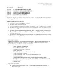
Government approval is required for submittals with a "G" designation;submittals not having a "G" designation are for Contractor Quality Controlapproval information only. When used, a designation following the "G"designation identifies the office that will review the submittal for theGovernment. The following shall be submitted in accordance with Section 0<strong>13</strong>3 00 SUBMITTAL PROCEDURES:SD-02 Shop DrawingsShop Drawings; GThree copies of the Sprinkler System Shop Drawings, no later than<strong>21</strong> days prior to the start of sprinkler system installation.As-Built DrawingsAs-built shop drawings, at least 14 days after completion of theFinal Tests. The Sprinkler System Drawings shall be updated toreflect as-built conditions after all related work is completed.Provide full size hard copy on paper and electronic drawings inAutoCad on CD.SD-03 Product DataFire Protection Related SubmittalsA list of the Fire Protection Related Submittals, no later than 7days after the approval of the Fire Protection Specialist.Sway Bracing; GFor systems that are required to be protected against damage fromearthquakes, load calculations shall be provided for sizing of swaybracing.Materials and Equipment; GManufacturer's catalog data included with the Sprinkler SystemDrawings for all items specified herein. The data shall behighlighted to show model, size, options, etc., that are intendedfor consideration. Data shall be adequate to demonstratecompliance with all contract requirements. In addition, a completeequipment list that includes equipment description, model numberand quantity shall be provided.Hydraulic Calculations; GHydraulic calculations, including a drawing showing hydraulicreference points and pipe segments.Spare PartsSpare parts data shall be included for each different item ofmaterial and equipment specified.Preliminary Tests; G<strong>SECTION</strong> <strong>21</strong> <strong>13</strong> <strong>13</strong>.00 <strong>10</strong> Page 7
Proposed procedures for Preliminary Tests, no later than 14 daysprior to the proposed start of the tests. Proposed date and timeto begin the preliminary tests.Final Acceptance Test; GProposed procedures for Final Acceptance Test, no later than 14days prior to the proposed start of the tests. Proposed date andtime to begin Final Acceptance Test, submitted with the FinalAcceptance Test Procedures. Notification shall be provided atleast 14 days prior to the proposed start of the test.Notification shall include a copy of the Contractor's Material &Test Certificates.On-site Training; GProposed On-site Training schedule, at least 14 days prior to thestart of related training.Fire Protection Specialist; GThe name and documentation of certification of the proposed FireProtection Specialists, no later than 14 days after the Notice toProceed and prior to the submittal of the sprinkler system drawingsand hydraulic calculations.Sprinkler System Installer; GThe name and documentation of certification of the proposedSprinkler System Installer, concurrent with submittal of the FireProtection Specialist Qualifications.SD-06 Test ReportsPreliminary Test Report; GThree copies of the completed Preliminary Test Report, no laterthan 7 days after the completion of the Preliminary Tests. ThePreliminary Tests Report shall include both the Contractor'sMaterial and Test Certificate for Underground Piping and theContractor's Material and Test Certificate for Aboveground Piping.All items in the Preliminary Tests Report shall be signed by theFire Protection Specialist.Final Acceptance Test Report; GThree copies of the completed Final Acceptance Tests Reports, nolater than 7 days after the completion of the Final AcceptanceTests. All items in the Final Acceptance Report shall be signed bythe Fire Protection Specialist.SD-07 CertificatesInspection by Fire Protection Specialist; GConcurrent with the Final Acceptance Test Report, certificationby the Fire Protection Specialist that the sprinkler system is<strong>SECTION</strong> <strong>21</strong> <strong>13</strong> <strong>13</strong>.00 <strong>10</strong> Page 8
installed in accordance with the contract requirements, includingsigned approval of the Preliminary and Final Acceptance TestReports.Certificate of Fitness; GProvide Certificate of Fitness for any individual, business, orfirm engaged in the inspecting, designing, testing, maintaining orservicing of fire and life safety systems.SD-<strong>10</strong> Operation and Maintenance DataOperating and Maintenance InstructionsSubmit one electronic (.pdf) version and 2 hard copies of manualslisting step-by-step procedures required for system startup,operation, shutdown, and routine maintenance, at least 14 daysprior to field training. The manuals shall include themanufacturer's name, model number, parts list, list of parts andtools that should be kept in stock by the owner for routinemaintenance including the name of a local supplier, simplifiedwiring and controls diagrams, troubleshooting guide, andrecommended service organization (including address and telephonenumber) for each item of equipment. Each service organizationsubmitted shall be capable of providing 4 hour on-site response toa service call on an emergency basis.1.7 HYDRAULIC CALCULATIONSHydraulic calculations shall be as outlined in NFPA <strong>13</strong> except thatcalculations shall be performed by computer using software intendedspecifically for fire protection system design using the design data shownon the drawings. Software that uses k-factors for typical branch lines isnot acceptable. Calculations shall be based on the water supply data shownon the drawings. Calculations shall substantiate that the design area usedin the calculations is the most demanding hydraulically. Water supplycurves and system requirements shall be plotted on semi-logarithmic graphpaper so as to present a summary of the complete hydraulic calculation. Asummary sheet listing sprinklers in the design area and their respectivehydraulic reference points, elevations, actual discharge pressures andactual flows shall be provided. Elevations of hydraulic reference points(nodes) shall be indicated. Documentation shall identify each pipeindividually and the nodes connected thereto. The diameter, length, flow,velocity, friction loss, number and type fittings, total friction loss inthe pipe, equivalent pipe length and Hazen-Williams coefficient shall beindicated for each pipe. For gridded systems, calculations shall showpeaking of demand area friction loss to verify that the hydraulically mostdemanding area is being used. Also for gridded systems, a flow diagramindicating the quantity and direction of flows shall be included. A drawingshowing hydraulic reference points (nodes) and pipe designations used in thecalculations shall be included and shall be independent of shop drawings.1.8 FIRE PROTECTION SPECIALISTWork specified in this section shall be performed under the supervision ofand certified by the Fire Protection Specialist. The Fire ProtectionSpecialist shall be an individual who is a registered professional engineer<strong>SECTION</strong> <strong>21</strong> <strong>13</strong> <strong>13</strong>.00 <strong>10</strong> Page 9
and a Full Member of the Society of Fire Protection Engineers or who iscertified as a Level III or IV Technician by National Institute forCertification in Engineering Technologies (NICET) in the Automatic SprinklerSystem Layout subfield of Fire Protection Engineering Technology inaccordance with NICET <strong>10</strong>14-7. The Fire Protection Specialist shall beregularly engaged in the design and installation of the type and complexityof system specified in the Contract documents, and shall have served in asimilar capacity for at least three systems that have performed in themanner intended for a period of not less than 6 months. Any individual,business, or firm engaged in the inspecting, testing, maintaining, designingor servicing of fire and life safety systems and equipment shall becertified to perform these activities in accordance with Appendix G of FLREG 420-30. A certificate of fitness can be obtained by completing theEmployee Application for Certification of Fitness with supportingcredentials to the <strong>JBLM</strong> Fire Prevention branch. Allow five working days forprocessing of application for Certificate of Fitness. Contact the <strong>JBLM</strong> FirePrevention Branch at 253-966-7155 or 253-966-1764 for additionalinformation. Submit a copy of certificate of fitness to the ContractingOfficer or the Contracting Officer's Representative prior to starting workon life safety system and equipment.1.9 SPRINKLER SYSTEM INSTALLERWork specified in this section shall be performed by the Sprinkler SystemInstaller. The Sprinkler System Installer shall be regularly engaged in theinstallation of the type and complexity of system specified in the Contractdocuments, and shall have served in a similar capacity for at least threesystems that have performed in the manner intended for a period of not lessthan 6 months. Any individual, business, or firm engaged in the inspecting,testing, maintaining, designing or servicing of fire and life safety systemsand equipment shall be certified to perform these activities in accordancewith Appendix G of FL REG 420-30. A certificate of fitness can be obtainedby completing the Employee Application for Certification of Fitness withsupporting credentials to the <strong>JBLM</strong> Fire Prevention branch. Allow fiveworking days for processing of application for Certificate of Fitness.Contact the <strong>JBLM</strong> Fire Prevention Branch at 253-966-7155 or 253-966-1764 foradditional information. Submit a copy of certificate of fitness to theContracting Officer or the Contracting Officer's Representative prior tostarting work on life safety system and equipment.1.<strong>10</strong> REGULATORY REQUIREMENTSCompliance with referenced NFPA standards is mandatory. This includesadvisory provisions listed in the appendices of such standards, as thoughthe word "shall" had been substituted for the word "should" wherever itappears. In the event of a conflict between specific provisions of thisspecification and applicable NFPA standards, NFPA shall govern. Referenceto "authority having jurisdiction" shall be interpreted to be as defined byUFC 3-600-01.1.11 SPARE PARTSThe Contractor shall submit spare parts data for each different item ofmaterial and equipment specified. The data shall include a complete list ofparts and supplies, with current unit prices and source of supply, and alist of parts recommended by the manufacturer to be replaced after 1 yearand 3 years of service. A list of special tools and test equipment required<strong>SECTION</strong> <strong>21</strong> <strong>13</strong> <strong>13</strong>.00 <strong>10</strong> Page <strong>10</strong>
for maintenance and testing of the products supplied by the Contractor shallbe included.1.12 SHOP DRAWINGSThe Sprinkler System Shop Drawings shall conform to the requirementsestablished for working plans as prescribed in NFPA <strong>13</strong>. Drawings shallinclude plan and elevation views demonstrating that the equipment will fitthe allotted spaces with clearance for installation and maintenance. Eachset of drawings shall include the following:a. Descriptive index of drawings in the submittal with drawings listedin sequence by drawing number. A legend identifying device symbols,nomenclature, and conventions used.b. Floor plans drawn to a scale not less than 1/8" = 1'-0" whichclearly show locations of sprinklers, risers, pipe hangers, seismicseparation assemblies, sway bracing, inspector's test connections,drains, and other applicable details necessary to clearly describe theproposed arrangement. Each type of fitting used and the locations ofbushings, reducing couplings, and welded joints shall be indicated.c. Actual center-to-center dimensions between sprinklers on branchlines and between branch lines; from end sprinklers to adjacent walls;from walls to branch lines; from sprinkler feed mains, cross-mains andbranch lines to finished floor and roof or ceiling. A detail shallshow the dimension from the sprinkler and sprinkler deflector to theceiling in finished areas.d. Longitudinal and transverse building sections showing typicalbranch line and cross-main pipe routing as well as elevation of eachtypical sprinkler above finished floor.e. Details of each type of riser assembly; pipe hanger; sway bracingfor earthquake protection, and restraint of underground water main atpoint-of-entry into the building, and electrical devices andinterconnecting wiring.PART 2PRODUCTS2.1 STANDARD PRODUCTSMaterials and equipment shall be standard products of a manufacturerregularly engaged in the manufacture of such products and shall essentiallyduplicate items that have been in satisfactory use for at least 2 yearsprior to bid opening.2.2 NAMEPLATESAll equipment shall have a nameplate that identifies the manufacturer'sname, address, type or style, model or serial number, and catalog number.2.3 REQUIREMENTS FOR FIRE PROTECTION SERVICEMaterials and Equipment shall have been tested by Underwriters Laboratories,Inc. and listed in UL Fire Prot Dir or approved by Factory Mutual and listedin FM P7825a and FM P7825b. Where the terms "listed" or "approved" appear<strong>SECTION</strong> <strong>21</strong> <strong>13</strong> <strong>13</strong>.00 <strong>10</strong> Page 11
in this specification, such shall mean listed in UL Fire Prot Dir or FMP7825a and FM P7825b2.4 UNDERGROUND PIPING COMPONENTS2.4.1 PipePiping from a point 6 inches above the floor to a point 5 feet outside thebuilding wall shall be ductile iron with a rated working pressure of 175 psiconforming to AWWA C151/A<strong>21</strong>.51, with cement mortar lining conforming to AWWAC<strong>10</strong>4/A<strong>21</strong>.4. Piping more than 5 feet outside the building walls shall complywith Section 33 11 00 WATER DISTRIBUTION.2.4.2 Fittings and GasketsFittings shall be ductile iron conforming to AWWA C1<strong>10</strong>/A<strong>21</strong>.<strong>10</strong>. Gaskets shallbe suitable in design and size for the pipe with which such gaskets are tobe used. Gaskets for ductile iron pipe joints shall conform to AWWAC111/A<strong>21</strong>.11.2.4.3 Gate Valve and Indicator PostsGate valves for underground installation shall be of the inside screw typewith counter-clockwise rotation to open. Where indicating type valves areshown or required, indicating valves shall be gate valves with an approvedindicator post of a length to permit the top of the post to be located 3feet above finished grade. Gate valves and indicator posts shall be listedin UL Fire Prot Dir or FM P7825a and FM P7825b.2.5 ABOVEGROUND PIPING COMPONENTSAboveground piping shall be steel or copper.residential occupancies.Will be used only in2.5.1 Steel Piping Components2.5.1.1 Steel PipeExcept as modified herein, steel pipe shall be black galvanized whereindicated as permitted by NFPA <strong>13</strong> and shall conform to applicable provisionsof ASTM A 795/A 795M, ASTM A 53/A 53M, or ASTM A <strong>13</strong>5/A <strong>13</strong>5M. Pipe in whichthreads or grooves are cut or rolled formed shall be Schedule 40 or shall belisted by Underwriters' Laboratories to have a corrosion resistance ratio(CRR) of 1.0 or greater after threads or grooves are cut or rolled formed.Pipe shall be marked with the name of the manufacturer, kind of pipe, andASTM designation. Identify the correct pipe material requirement IAW theappropriate NFPA and UFC 3-600-01.2.5.1.2 Fittings for Non-Grooved Steel PipeFittings shall be cast iron conforming to ASME B16.4, steel conforming toASME B16.9 or ASME B16.11, or malleable iron conforming to ASME B16.3. Steelpress fittings shall be approved for fire protection systems. Galvanizedfittings shall be used for piping systems or portions of piping systemsutilizing galvanized piping. Fittings into which sprinklers, drop nipplesor riser nipples (sprigs) are screwed shall be threaded type. Plain-end<strong>SECTION</strong> <strong>21</strong> <strong>13</strong> <strong>13</strong>.00 <strong>10</strong> Page 12
fittings with mechanical couplings, fittings that use steel gripping devicesto bite into the pipe and segmented welded fittings shall not be used.2.5.1.3 Grooved Mechanical Joints and FittingsJoints and fittings shall be designed for not less than 175 psi service andshall be the product of the same manufacturer; segmented welded fittingsshall not be used. Fitting and coupling houses shall be malleable ironconforming to ASTM A 47/A 47M, Grade 325<strong>10</strong>; ductile iron conforming to ASTMA 536, Grade 65-45-12. Gasket shall be the flush type that fills the entirecavity between the fitting and the pipe. Nuts and bolts shall be heattreatedsteel conforming to ASTM A 183 and shall be cadmium plated or zincelectroplated.2.5.1.4 FlangesFlanges shall conform to NFPA <strong>13</strong> and ASME B16.1. Gaskets shall be nonasbestoscompressed material in accordance with ASME B16.<strong>21</strong>, 1/16 inchthick, and full face or self-centering flat ring type.2.5.1.5 Bolts, Nut, and WashersBolts shall be conform to ASTM A 449, Type 1 and shall extend no less thanthree full threads beyond the nut with bolts tightened to the requiredtorque. Nuts shall be ASTM A 193/A 193M, Grade 5. Washers shall meet therequirements of ASTM F 436. Flat circular washers shall be provided underall bolt heads and nuts.2.5.2 Copper Tube Components2.5.2.1 Copper TubeCopper tube shall conform to ASTM B 88, Types L and M.2.5.2.2 Copper Fittings and JointsCast copper alloy solder-joint pressure fittings shall conform to ASMEB16.18 and wrought copper and bronze solder-joint pressure fittings shallconform to ASME B16.22 and ASTM B 75. Cast copper alloy fittings for flaredcopper tube shall conform to ASME B16.26and ASTM B 62. Brass or bronzeadapters for brazed tubing may be used for connecting tubing to flanges andto threaded ends of valves and equipment. Extracted brazed tee jointsproduced with an acceptable tool and installed as recommended by themanufacturer may be used. Grooved mechanical joints and fittings shall bedesigned for not less than 125 psig service and shall be the product of thesame manufacturer. Grooved fitting and mechanical coupling housing shall beductile iron conforming to ASTM A 536. Gaskets for use in grooved jointsshall be molded synthetic polymer of pressure responsive design and shallconform to ASTM D 2000 for circulating medium up to 230 degrees F. Groovedjoints shall conform to AWWA C606. Coupling nuts and bolts for use ingrooved joints shall be steel and shall conform to ASTM A 183.2.5.3 Plastic Piping ComponentsPlastic pipe may only be used in residential applications.<strong>SECTION</strong> <strong>21</strong> <strong>13</strong> <strong>13</strong>.00 <strong>10</strong> Page <strong>13</strong>
2.5.3.1 Plastic PipePlastic pipe shall be chlorinated polyvinyl chloride (CPVC) conforming toASTM F 442/F 442M, 175 psi rating and listed in UL Fire Prot Dir for use inwet pipe sprinkler systems.2.5.3.2 Plastic FittingsPlastic fitting shall be chlorinated polyvinyl chloride (CPVC) as listed inUL Fire Prot Dir for use in wet pipe sprinkler systems.2.5.4 Pipe HangersHangers shall be listed in UL Fire Prot Dir or FM P7825a and FM P7825b andof the type suitable for the application, construction, and pipe type andsized to be supported.2.5.5 Valves2.5.5.1 Control Valve and Gate ValveManually operated sprinkler control valve and gate valve shall be outsidestem and yoke (OS&Y) type and shall be listed in UL Bld Mat Dir or FM P7825aand FM P7825b.2.5.5.2 Check ValveCheck valve 2 inches and larger shall be listed in UL Bld Mat Dir or FMP7825a and FM P7825b. Check valves 4 inches and larger shall be of theswing type with flanged cast iron body and flanged inspection plate, shallhave a clear waterway and shall meet the requirements of MSS SP-71, for Type3 or 4.2.5.5.3 Hose ValveValve shall comply with UL 668 and shall have a minimum rating of 300 psi.Valve shall be non-rising stem, all bronze, 90 degree angle type, with 2-1/2inch American National Standard Fire Hose Screw Thread (NH) male outlet inaccordance with NFPA 1963. Hose valve shall be provided with 2-1/2 to 1-1/2inch reducer. Hose valves shall be equipped with lugged cap with dripdrain, cap gasket and chain. Valve finish shall be polished brass or roughchrome plated.2.6 WATERFLOW ALARMElectrically operated, exterior-mounted, waterflow alarm bell shall beprovided and installed in accordance with NFPA <strong>13</strong>. Waterflow alarm bellshall be rated 24 VDC and shall be connected to the Fire Alarm ControlPanel(FACP) in accordance with Section 28 31 64.00 <strong>10</strong> FIRE DETECTION ANDALARM SYSTEM, ADDRESSABLE.2.7 ALARM INITIATING AND SUPERVISORY DEVICES2.7.1 Sprinkler Waterflow Indicator Switch, Vane TypeSwitch shall be vane type with a pipe saddle and cast aluminum housing. Theelectro-mechanical device shall include a flexible, low-density polyethylene<strong>SECTION</strong> <strong>21</strong> <strong>13</strong> <strong>13</strong>.00 <strong>10</strong> Page 14
paddle conforming to the inside diameter of the fire protection pipe. Thedevice shall sense water movements and be capable of detecting a sustainedflow of <strong>10</strong> gpm or greater. The device shall contain a retard deviceadjustable from 0 to 90 seconds to reduce the possibility of false alarmscaused by transient flow surges. The switch shall be tamper resistant andcontain two SPDT (Form C) contacts arranged to transfer upon removal of thehousing cover, and shall be equipped with a silicone rubber gasket to assurepositive water seal and a dustproof cover and gasket to seal the mechanismfrom dirt and moisture. Electrically operated, exterior-mounted, waterflowalarm bell shall be provided and installed in accordance with NFPA <strong>13</strong>.Waterflow alarm bell shall be rated 24 VDC and shall be connected to the FireAlarm Control Panel(FACP) in accordance with Section 28 31 64.00 <strong>10</strong> FIREDETECTION AND ALARM SYSTEM, ADDRESSABLE.2.7.2 Valve Supervisory (Tamper) SwitchSwitch shall be suitable for mounting to the type of control valve to besupervised open. The switch shall be tamper resistant and contain one setof SPDT (Form C) contacts arranged to transfer upon removal of the housingcover or closure of the valve of more than two rotations of the valve stem.2.8 FIRE DEPARTMENT CONNECTIONFire department connection shall be projecting or flush type with cast brassbody, matching wall escutcheon lettered "Auto Spkr" with a chromium platedfinish. The connection shall have two inlets with individual self-closingclappers, caps with drip drains and chains. Female inlets shall have 2-1/2inch diameter American National Fire Hose Connection Screw Threads (NH) perNFPA 1963. This section does not address remote FDC's. Remote FDC's shouldbe specified when desired. Ensure the remote FDC is stenciled with thebuilding number for easy identification.2.9 SPRINKLERSSprinklers with internal O-rings shall not be used. Sprinklers shall beused in accordance with their listed coverage limitations. Temperatureclassification shall be as indicated. Sprinklers in high heat areasincluding attic spaces or in close proximity to unit heaters shall havetemperature classification in accordance with NFPA <strong>13</strong>. Extended coveragesprinklers shall not be used.2.9.1 Concealed SprinklerConcealed sprinkler shall be chrome-plated quick-response type and shallhave a nominal 1/2 inch or 17/32 inch orifice.2.9.2 Recessed SprinklerRecessed sprinkler shall be chrome-plated quick-response type and shall havea nominal 1/2 inch or 17/32 inch orifice.2.9.3 Flush SprinklerFlush sprinkler shall be chrome-plated quick-response type and shall have anominal 1/2 inch or 17/32 inch orifice.<strong>SECTION</strong> <strong>21</strong> <strong>13</strong> <strong>13</strong>.00 <strong>10</strong> Page 15
2.9.4 Pendent SprinklerPendent sprinkler shall be of the fusible strut or glass bulb type, recessedquick-response type with nominal 1/2 inch or 17/32 inch orifice. Pendentsprinklers shall have a polished chrome.2.9.5 Upright SprinklerUpright sprinkler shall be chrome-plated quick-response type and shall havea nominal 1/2 inch or 17/32 inch orifice.2.9.6 Sidewall SprinklerSidewall sprinkler shall have a nominal 1/2 inch orifice. Sidewallsprinkler shall have a polished chrome finish. Sidewall sprinkler shall bethe quick-response type.2.9.7 Residential SprinklerResidential sprinkler shall be the pendent and sidewall type with nominal1/2 inch orifice. Residential sprinkler shall have a polished chromefinish.2.9.8 Intermediate Level Rack SprinklerIntermediate level rack sprinkler shall be of the upright or pendent typewith nominal 1/2 inch orifice and minimum "K" factor of 5.5. The sprinklershall be equipped with a deflector plate to shield the fusible element fromwater discharged above it.2.9.9 Corrosion Resistant SprinklerCorrosion resistant sprinkler shall be the upright or pendent type installedin locations as indicated. Corrosion resistant coatings shall be factoryappliedby the sprinkler manufacturer.2.9.<strong>10</strong> Dry Sprinkler AssemblyDry sprinkler assembly shall be of the pendent, upright, or sidewall, 45-degree type as indicated. Assembly shall include an integral escutcheon.Maximum length shall not exceed maximum indicated in UL Fire Prot Dir.Sprinklers shall have a polished chrome.2.<strong>10</strong> DISINFECTING MATERIALSThis section only applies to underground pipe, it is a requirement todisinfect above ground pipe after the back flow preventer.2.<strong>10</strong>.1 Liquid ChlorineLiquid chlorine shall conform to AWWA B301.2.<strong>10</strong>.2 HypochloritesCalcium hypochlorite and sodium hypochlorite shall conform to AWWA B300.<strong>SECTION</strong> <strong>21</strong> <strong>13</strong> <strong>13</strong>.00 <strong>10</strong> Page 16
2.11 ACCESSORIES2.11.1 Sprinkler CabinetSpare sprinklers shall be provided in accordance with NFPA <strong>13</strong> and shall bepacked in a suitable metal or plastic cabinet. Spare sprinklers shall berepresentative of, and in proportion to, the number of each type andtemperature rating of the sprinklers installed. At least one wrench of eachtype required shall be provided.2.11.2 Pendent Sprinkler EscutcheonEscutcheon shall be one-piece metallic type with a depth of less than 3/4inch and suitable for installation on pendent sprinklers. The escutcheonshall have a factory finish that matches the pendent sprinkler heads.2.11.3 Pipe EscutcheonEscutcheon shall be polished chromium-plated zinc alloy, or polishedchromium-plated copper alloy. Escutcheons shall be either one-piece orsplit-pattern, held in place by internal spring tension or set screw.2.11.4 Sprinkler GuardGuard shall be a steel wire cage designed to encase the sprinkler andprotect it from mechanical damage. Guards shall be provided on sprinklerslocated as indicated.2.11.5 Identification SignValve identification sign shall be minimum 6 inches wide x 2 inches high withenamel baked finish on minimum 18 gauge steel or 0.024 inch aluminum with redletters on a white background or white letters on red background. Wording ofsign shall include, but not be limited to "main drain," "auxiliary drain,""inspector's test," "alarm test," "alarm line," and similar wording asrequired to identify operational components. Signs shall be affixed to eachcontrol valve, inspector test valve, main drain, auxiliary drain, test valve,and similar valves as appropriate or as required by NFPA <strong>13</strong>. Hydraulicdesign data nameplates shall be permanently affixed to each sprinkler riseras specified in NFPA <strong>13</strong>. Provide and install “Hydraulic Design InformationSign” and “General Information Sign” per NFPA <strong>13</strong> chapter 24.2.12 FIRE HOSE REEL ASSEMBLYAssembly shall include nozzle, fire hose, reel, 1-1/2 inch valve, andbracket suitable for wall mounting. The assembly shall be semi-automatictype complete with Underwriters clip which permits controlled one-manoperation whereby control valve can be opened, hose unreeled and clipreleased by pulling on hose. Valve shall be non-rising stem, all bronze,angle type with 1-1/2 inch American National Standard Fire Hose Screw Thread(NH) male outlet in accordance with NFPA 1963. Reel shall be of steelconstruction with red enamel finish and shall be equipped with<strong>10</strong>0 feet of 1-1/2 inch rubber lined fire hose. Nozzle shall be of the industrialcombination fog-straight stream type with shutoff. Components of theassembly shall be listed in UL Fire Prot Dir.<strong>SECTION</strong> <strong>21</strong> <strong>13</strong> <strong>13</strong>.00 <strong>10</strong> Page 17
2.<strong>13</strong> DOUBLE-CHECK VALVE BACKFLOW PREVENTION ASSEMBLYDouble-check backflow prevention assembly shall comply with ASSE <strong>10</strong>15. Theassembly shall have a bronze, cast-iron or stainless steel body with flangedends. The assembly shall include pressure gauge test ports and OS&Y shutoffvalves on the inlet and outlet, 2-positive-seating check valve forcontinuous pressure application, and four test cocks. Assemblies shall berated for working pressure of 175 psi The maximum pressure loss shall be 6psi at a flow rate equal to the sprinkler water demand, at the location ofthe assembly. A test port for a pressure gauge shall be provided bothupstream and downstream of the double check backflow prevention assemblyvalves. Backflow preventers installed in Washington State must meet theState of Washington requirements.PART 3EXECUTION3.1 FIRE PROTECTION RELATED SUBMITTALSThe Fire Protection Specialist shall prepare a list of the submittals fromthe Contract Submittal Register that relate to the successful installationof the sprinkler systems(s). The submittals identified on this list shallbe accompanied by a letter of approval signed and dated by the FireProtection Specialist when submitted to the Government.3.2 INSTALLATION REQUIREMENTSThe installation shall be in accordance with the applicable provisions ofNFPA <strong>13</strong>, NFPA 24, and UFC 3-600-01 and publications referenced therein.Installation of in-rack sprinklers shall comply with applicable provisions ofNFPA <strong>13</strong>. Any individual, business, or firm engaged in the inspecting,testing, maintaining, designing, or servicing of fire and life safety systemsand equipment shall be certified to perform these activities in accordancewith Appendix G of FL REG 420-30. Prior to starting work on any life safetysystem the contractor must submit paperwork to, and obtain, a Certificate ofFitness from the fire inspection branch. The certificate of fitness providesproof that the contractor is qualified to work on life safety systems. Acertificate of fitness can be obtained by completing the Employee Applicationfor Certification of Fitness with supporting credentials to the Joint BaseLewis-McChord Fire Prevention branch. Allow five working days for processingof application for Certificate of Fitness. Contact the Joint Base Lewis-McChord Fire Prevention Branch at 253-966-7155 or 253-966-1764 for additionalinformation. Submit a copy of certificate of fitness to the ContractingOfficer or the Contracting Officer's Representative prior to starting work onlife safety system and equipment IAW Section 28 31 64.00 <strong>10</strong> of the <strong>JBLM</strong>Design Standards.3.3 INSPECTION BY FIRE PROTECTION SPECIALISTThe Fire Protection Specialist shall inspect the sprinkler systemperiodically during the installation to assure that the sprinkler system isbeing provided and installed in accordance with the contract requirements.The Fire Protection Specialist shall witness the preliminary and finaltests, and shall sign the test results. The Fire Protection Specialist,after completion of the system inspections and a successful final test,shall certify in writing that the system has been installed in accordancewith the contract requirements. Any discrepancy shall be brought to the<strong>SECTION</strong> <strong>21</strong> <strong>13</strong> <strong>13</strong>.00 <strong>10</strong> Page 18
attention of the Contracting Officer in writing, no later than three workingdays after the discrepancy is discovered.3.4 ABOVEGROUND PIPING INSTALLATION3.4.1 Protection of Piping Against Earthquake DamageThe system piping shall be seismically protected against damage fromearthquakes. This requirement is not subject to determination under NFPA<strong>13</strong>. Install the seismic protection of the system piping in accordance withUFC 3-3<strong>10</strong>-04, NFPA <strong>13</strong> and Annex A. Include the required features identifiedtherein that are applicable to the specific piping system.3.4.2 Piping in Exposed AreasExposed piping shall be installed so as not to diminish exit access widths,corridors or equipment access. Exposed horizontal piping, including drainpiping, shall be installed to provide maximum headroom.3.4.3 Piping in Finished AreasIn areas with suspended or dropped ceilings and in areas with concealedspaces above the ceiling, piping shall be concealed above ceilings. Pipingshall be inspected, tested and approved before being concealed. Risers andsimilar vertical runs of piping in finished areas shall be concealed.3.4.4 Pendent SprinklersDrop nipples to pendent sprinklers shall consist of minimum 1 inch pipe witha reducing coupling into which the sprinkler shall be threaded. Hangersshall be provided on arm-overs to drop nipples supplying pendent sprinklerswhen the arm-over exceeds 12 inches for steel pipe or 6 inches for coppertubing. Where sprinklers are installed below suspended or dropped ceilings,drop nipples shall be cut such that sprinkler ceiling plates or escutcheonsare of a uniform depth throughout the finished space. The outlet of thereducing coupling shall not extend more than 1 inch below the underside ofthe ceiling. On pendent sprinklers installed below suspended or droppedceilings, the distance from the sprinkler deflector to the underside of theceiling shall not exceed 4 inches. Recessed pendent sprinklers shall beinstalled such that the distance from the sprinkler deflector to theunderside of the ceiling shall not exceed the manufacturer's listed rangeand shall be of uniform depth throughout the finished area.3.4.4.1 Pendent Sprinkler LocationsPendent sprinklers in suspended ceilings shall be a minimum of 6 inches fromceiling grid.3.4.5 Upright SprinklersRiser nipples or "sprigs" to upright sprinklers shall contain no fittingsbetween the branch line tee and the reducing coupling at the sprinkler.Riser nipples exceeding 30 inches in length shall be individually supported.3.4.6 Pipe Joints<strong>SECTION</strong> <strong>21</strong> <strong>13</strong> <strong>13</strong>.00 <strong>10</strong> Page 19
Pipe joints shall conform to NFPA <strong>13</strong>, except as modified herein. Not morethan four threads shall show after joint is made up. Welded joints will bepermitted, only if welding operations are performed as required by NFPA <strong>13</strong>at the Contractor's fabrication shop, not at the project construction site.Flanged joints shall be provided where indicated or required by NFPA <strong>13</strong>.Grooved pipe and fittings shall be prepared in accordance with themanufacturer's latest published specification according to pipe material,wall thickness and size. Grooved couplings, fittings and grooving toolsshall be products of the same manufacturer. For copper tubing, pipe andgroove dimensions shall comply with the tolerances specified by the couplingmanufacturer. The diameter of grooves made in the field shall be measuredusing a "go/no-go" gauge, vernier or dial caliper, narrow-land micrometer,or other method specifically approved by the coupling manufacturer for theintended application. Groove width and dimension of groove from end of pipeshall be measured and recorded for each change in grooving tool setup toverify compliance with coupling manufacturer's tolerances. Grooved jointsshall not be used in concealed locations, such as behind solid walls orceilings, unless an access panel is shown on the drawings for servicing oradjusting the joint.3.4.7 ReducersReductions in pipe sizes shall be made with one-piece tapered reducingfittings. The use of grooved-end or rubber-gasketed reducing couplings willnot be permitted. When standard fittings of the required size are notmanufactured, single bushings of the face type will be permitted. Whereused, face bushings shall be installed with the outer face flush with theface of the fitting opening being reduced. Bushings shall not be used inelbow fittings, in more than one outlet of a tee, in more than two outletsof a cross, or where the reduction in size is less than 1/2 inch.3.4.8 Pipe PenetrationsCutting structural members for passage of pipes or for pipe-hangerfastenings will not be permitted. Pipes that must penetrate concrete ormasonry walls or concrete floors shall be core-drilled and provided withpipe sleeves. Each sleeve shall be Schedule 40 galvanized steel, ductileiron or cast iron pipe and shall extend through its respective wall or floorand be cut flush with each wall surface. Sleeves shall provide requiredclearance between the pipe and the sleeve per NFPA <strong>13</strong>. The space betweenthe sleeve and the pipe shall be firmly packed with mineral wool insulation.Where pipes penetrate fire walls, fire partitions, or floors, pipes shall befire stopped in accordance with Section 07 84 00 FIRESTOPPING. Inpenetrations that are not fire-rated or not a floor penetration, the spacebetween the sleeve and the pipe shall be sealed at both ends with plasticwaterproof cement that will dry to a firm but pliable mass or with amechanically adjustable segmented elastomer seal.3.4.9 EscutcheonsEscutcheons shall be provided for pipe penetration of ceilings and walls.Escutcheons shall be securely fastened to the pipe at surfaces through whichpiping passes.3.4.<strong>10</strong> Inspector's Test Connection<strong>SECTION</strong> <strong>21</strong> <strong>13</strong> <strong>13</strong>.00 <strong>10</strong> Page 20
Unless otherwise indicated, test connection shall consist of 1 inch pipeconnected to the remote branch line or at the riser as a combination testand drain valve; a test valve located approximately 7 feet above the floor;a smooth bore brass outlet equivalent to the smallest orifice sprinkler usedin the system; and a painted metal identification sign affixed to the valvewith the words "Inspector's Test." The discharge orifice shall be locatedoutside the building wall directed so as not to cause damage to adjacentconstruction or landscaping during full flow discharge.3.4.11 DrainsMain drain piping shall be provided to discharge at the location indicated.Auxiliary drains shall be provided as required by NFPA <strong>13</strong>.3.4.12 Installation of Fire Department ConnectionConnection shall be mounted on the exterior wall approximately 3 feet abovefinished grade or adjacent to and on the sprinkler system side of thebackflow preventer. The piping between the connection and the check valveshall be provided with an automatic drip in accordance with NFPA <strong>13</strong> andarranged to drain to the outside.3.4.<strong>13</strong> Identification SignsSigns shall be affixed to each control valve, inspector test valve, maindrain, auxiliary drain, test valve, and similar valves as appropriate or asrequired by NFPA <strong>13</strong>. Hydraulic design data nameplates shall be permanentlyaffixed to each sprinkler riser as specified in NFPA <strong>13</strong>.3.5 UNDERGROUND PIPING INSTALLATIONThe fire protection water main shall be laid, and joints anchored, inaccordance with NFPA 24. Minimum depth of cover shall be 3 feet. Thesupply line shall terminate inside the building with a flanged piece, thebottom of which shall be set not less than 6 inches above the finishedfloor. A blind flange shall be installed temporarily on top of the flangedpiece to prevent the entrance of foreign matter into the supply line. Aconcrete thrust block shall be provided at the elbow where the pipe turns uptoward the floor. In addition, joints shall be anchored in accordance withNFPA 24 using pipe clamps and steel rods from the elbow to the flange abovethe floor and from the elbow to a pipe clamp in the horizontal run of pipe.Buried steel components shall be provided with a corrosion protectivecoating in accordance with AWWA C203. Piping more than 5 feet outside thebuilding walls shall meet the requirements of Section 33 11 00 WATERDISTRIBUTION. Underground pipe work will be performed by a State ofWashington level U underground contractor IAW WAC <strong>21</strong>2-80-043(2).3.6 EARTHWORKEarthwork shall be performed in accordance with applicable provisions ofSection 31 00 00 EARTHWORK.3.7 ELECTRICAL WORKExcept as modified herein, electric equipment and wiring shall be inaccordance with Sections 26 20 00 INTERIOR DISTRIBUTION SYSTEM, 28 31 33.00<strong>10</strong> FIRE ALARM REPORTING SYSTEM, RADIO TYPE, and 28 31 76 INTERIOR FIRE ALARM<strong>SECTION</strong> <strong>21</strong> <strong>13</strong> <strong>13</strong>.00 <strong>10</strong> Page <strong>21</strong>
AND MASS NOTIFICATION SYSTEM. Alarm signal wiring connected to the buildingfire alarm control system shall be in accordance with Section 28 31 64.00 <strong>10</strong>FIRE DETECTION AND ALARM SYSTEM, ADDRESSABLE. All wiring for supervisory andalarm circuits shall be #14 AWG solid copper installed in metallic tubing orconduit. Wiring color code shall remain uniform throughout the system.3.8 DISINFECTIONAfter all system components are installed and hydrostatic test(s) aresuccessfully completed, each portion of the sprinkler system to bedisinfected shall be thoroughly flushed with potable water until allentrained dirt and other foreign materials have been removed beforeintroducing chlorinating material. Flushing shall be conducted by removingthe flushing fitting of the cross mains and of the grid branch lines, andthen back-flushing through the sprinkler main drains. The chlorinatingmaterial shall be hypochlorites or liquid chlorine. Water chlorinationprocedure shall be in accordance with AWWA C651 and AWWA C652. Thechlorinating material shall be fed into the sprinkler piping at a constantrate of 50 parts per million (ppm). A properly adjusted hypochloritesolution injected into the system with a hypochlorinator, or liquid chlorineinjected into the system through a solution-fed chlorinator and booster pumpshall be used. Chlorination application shall continue until the entiresystem if filled. The water shall remain in the system for a minimum of 24hours. Each valve in the system shall be opened and closed several times toensure its proper disinfection. Following the 24-hour period, no less than25 ppm chlorine residual shall remain in the system. The system shall thenbe flushed with clean water until the residual chlorine is reduced to lessthan one part per million. Samples of water in disinfected containers forbacterial examination will be taken from several system locations which areapproved by the Contracting Officer. Samples shall be tested for totalcoliform organisms (coliform bacteria, fecal coliform, streptococcal, andother bacteria) in accordance with AWWA <strong>10</strong>084. The testing method shall beeither the multiple-tube fermentation technique or the membrane-filtertechnique. The disinfection shall be repeated until tests indicate theabsence of coliform organisms (zero mean coliform density per <strong>10</strong>0milliliters) in the samples for at least 2 full days. The system will notbe accepted until satisfactory bacteriological results have been obtained.After successful completion, verify installation of all sprinklers and plugsand pressure test the system.3.9 PIPE COLOR CODE MARKINGColor code marking of piping shall be as specified in Section 09 90 00PAINTS AND COATINGS.3.<strong>10</strong> PRELIMINARY TESTSThe system, including the underground water mains, and the abovegroundpiping and system components, shall be tested to assure that equipment andcomponents function as intended. The underground and aboveground interiorpiping systems and attached appurtenances subjected to system workingpressure shall be tested in accordance with NFPA <strong>13</strong> and NFPA 24. Uponcompletion of specified tests, the Contractor shall complete certificates asspecified in paragraph SUBMITTALS.3.<strong>10</strong>.1 Underground Piping<strong>SECTION</strong> <strong>21</strong> <strong>13</strong> <strong>13</strong>.00 <strong>10</strong> Page 22
3.<strong>10</strong>.1.1 FlushingUnderground piping shall be flushed in accordance with NFPA 24. Thisincludes the requirement to flush the lead-in connection to the fireprotection system at a flow rate not less that the calculated maximum waterdemand rate of the system.3.<strong>10</strong>.1.2 Hydrostatic TestingNew underground piping shall be hydrostatically tested in accordance withNFPA 24. The allowable leakage shall be measured at the specified testpressure by pumping from a calibrated container. The amount of leakage atthe joints shall not exceed 2 quarts per hour per <strong>10</strong>0 gaskets or joints,regardless of pipe diameter.3.<strong>10</strong>.2 Aboveground Piping3.<strong>10</strong>.2.1 Hydrostatic TestingAboveground piping shall be hydrostatically tested in accordance with NFPA<strong>13</strong> at not less than 200 psi or 50 psi in excess of maximum system operatingpressure and shall maintain that pressure without loss for 2 hours. Thereshall be no drop in gauge pressure or visible leakage when the system issubjected to the hydrostatic test. The test pressure shall be read from agauge located at the low elevation point of the system or portion beingtested.3.<strong>10</strong>.2.2 Backflow Prevention Assembly Forward Flow TestEach backflow prevention assembly shall be tested at system flow demand,including all applicable hose streams, as specified in NFPA <strong>13</strong>. BackflowPreventers shall be tested in accordance with Washington State requirements.The Contractor shall provide all equipment and instruments necessary toconduct a complete forward flow test, including 2.5 inch diameter hoses,playpipe nozzles, calibrated pressure gauges, and pitot tube gauge. TheContractor shall provide all necessary supports to safely secure hoses andnozzles during the test. At the system demand flow, the pressure readingsand pressure drop (friction) across the assembly shall be recorded. A metalplacard shall be provided on the backflow prevention assembly that lists thepressure readings both upstream and downstream of the assembly, totalpressure drop, and the system test flow rate. The pressure drop shall becompared to the manufacturer's data.3.<strong>10</strong>.3 Testing of Alarm DevicesEach alarm switch shall be tested by flowing water through the inspector'stest connection. Each water-operated alarm devices shall be tested toverify proper operation.3.<strong>10</strong>.4 Main Drain Flow TestFollowing flushing of the underground piping, a main drain test shall bemade to verify the adequacy of the water supply. Static and residualpressures shall be recorded on the certificate specified in paragraphSUBMITTALS. In addition, a main drain test shall be conducted each timeafter a main control valve is shut and opened.<strong>SECTION</strong> <strong>21</strong> <strong>13</strong> <strong>13</strong>.00 <strong>10</strong> Page 23
3.11 FINAL ACCEPTANCE TESTFinal Acceptance Test shall begin only when the Preliminary Test Report hasbeen approved. Coordinate with Public Works, Fire Department, andContracting Officer for required testing procedures. The Fire ProtectionSpecialist shall conduct the Final Acceptance Test and shall provide acomplete demonstration of the operation of the system. This shall includeoperation of control valves and flowing of inspector's test connections toverify operation of associated waterflow alarm switches. After operation ofcontrol valves has been completed, the main drain test shall be repeated toassure that control valves are in the open position. In addition, therepresentative shall have available copies of as-built drawings andcertificates of tests previously conducted. The installation shall not beconsidered accepted until identified discrepancies have been corrected andtest documentation is properly completed and received. The Contractor shallsubmit the Final Acceptance Test Report as specified in the Submittalsparagraph.3.12 ON-SITE TRAININGThe Fire Protection Specialist shall conduct a training course for operatingand maintenance personnel as designated by the Contracting Officer.Coordinate the training requirements for suppression systems with trainingfor the alarm system electronic hardware and software. See trainingrequirements in Section 28 31 64.00 <strong>10</strong> FIRE DETECTION AND ALARM SYSTEM,ADDRESSABLE. Training shall be provided for a period of 8 hours of normalworking time and shall start after the system is functionally complete andafter the Final Acceptance Test. The On-Site Training shall cover all ofthe items contained in the approved Operating and Maintenance Instructions.-- End of Section --<strong>SECTION</strong> <strong>21</strong> <strong>13</strong> <strong>13</strong>.00 <strong>10</strong> Page 24
<strong>SECTION</strong> <strong>21</strong> <strong>13</strong> <strong>13</strong>.00 <strong>10</strong> Page 25