33 11 00 Water Distribution.pdf - WPC
33 11 00 Water Distribution.pdf - WPC
33 11 00 Water Distribution.pdf - WPC

Create successful ePaper yourself
Turn your PDF publications into a flip-book with our unique Google optimized e-Paper software.
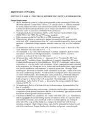
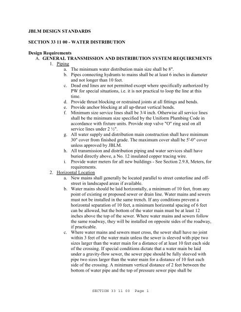
JBLM DESIGN STANDARDS<br />
SECTION <strong>33</strong> <strong>11</strong> <strong>00</strong> - WATER DISTRIBUTION<br />
Design Requirements<br />
A. GENERAL TRANSMISSION AND DISTRIBUTION SYSTEM REQUIREMENTS<br />
1. Piping<br />
a. The minimum water distribution main size shall be 8".<br />
b. Pipes connecting hydrants to mains shall be at least 6 inches in diameter<br />
and not longer than 10 feet.<br />
c. Dead end lines are not permitted except where specifically authorized by<br />
PW for special situations, i.e. it is not practical to loop the line at this<br />
time.<br />
d. Provide thrust blocking or restrained joints at all fittings and bends.<br />
e. Provide anchor blocking at all up-thrust vertical bends.<br />
f. Minimum size service lines shall be 3/4 inch. Otherwise all service lines<br />
shall be the minimum size specified by the Uniform Plumbing Code in<br />
accordance with fixture units. Provide stop valve "O" ring seal on all<br />
service lines under 2 ½".<br />
g. All water supply and distribution main construction shall have minimum<br />
30" cover from finished grade. The maximum cover shall be 5'-0" cover<br />
unless approved by JBLM.<br />
h. All transmission and distribution piping and water services shall have<br />
buried directly above, a No. 12 insulated copper tracing wire.<br />
i. Provide water meters for all new buildings - See Section 2.9.8, Meters, for<br />
requirements.<br />
2. Horizontal Location<br />
a. New mains shall generally be located parallel to street centerline and offstreet<br />
in landscaped areas if available.<br />
b. <strong>Water</strong> mains should be laid horizontally, a minimum of 10 feet, from any<br />
point of existing or proposed sewer or drain line. <strong>Water</strong> mains and sewers<br />
must not be installed in the same trench. If any conditions prevent a<br />
horizontal separation of 10 feet, a minimum horizontal spacing of 6 feet<br />
can be allowed, but the bottom of the water main must be at least 12<br />
inches above the top of the sewer. Where water mains and sewers follow<br />
the same roadway, they will be installed on opposite sides of the roadway,<br />
if practicable.<br />
c. Where water mains and sewers must cross, the sewer shall have no joint<br />
within 3 feet of the water main unless the sewer is sleeved with pipe two<br />
sizes larger than the water main for a distance of at least 10 feet each side<br />
of the crossing. If special conditions dictate that a water main be laid<br />
under a gravity-flow sewer, the sewer pipe should be fully sleeved with<br />
pipe two sizes larger than the water main for a distance of 10 feet each<br />
side of the crossing. A minimum vertical distance of 2 feet between the<br />
bottom of water pipe and the top of pressure sewer pipe shall be<br />
SECTION <strong>33</strong> <strong>11</strong> <strong>00</strong> Page 1
maintained. The sewer must be adequately supported to prevent settling<br />
and insure designed slope is maintained. See also TM5-813-5.<br />
3. Valves<br />
a. Valves shall be installed at intervals not greater than 5,<strong>00</strong>0 feet in<br />
transmission lines and 1,2<strong>00</strong> feet in distribution loops.<br />
b. At the intersections of distribution mains, the number of valves required is<br />
normally one less than the number of radiating mains. A cross will have 3<br />
valves and a tee will have 2 valves. The omitted valve will be from the<br />
line which principally supplies flow to the intersection.<br />
c. Valves shall be installed on laterals serving fire hydrants.<br />
d. Blowoff valves or fire hydrants should be installed at the ends of dead-end<br />
mains to allow periodic flushing of the mains. Primary feeder mains and<br />
larger distribution mains should have a blowoff valve in each valved<br />
section which should be installed at low points in the mains where the<br />
flushing water can be readily discharged to natural drainage channels.<br />
Blowoff valves must be designed so that operation which will result in<br />
erosion or destruction of wildlife is not permitted. Special care must be<br />
taken to eliminate the possibility of contaminated water entering the<br />
distribution system through blowoff valves which have not been tightly<br />
closed.<br />
e. Valve marker posts shall be provided for all valves placed outside of<br />
paved areas. All valve marker posts shall be marked with the distance to<br />
the valve referenced.<br />
4. Fire Hydrant Spacing<br />
a. Hydrant distribution shall conform to the standards shown in Table III-1<br />
and spacing shall conform to the guidelines given in UFC 3-6<strong>00</strong>-01.<br />
Table III-1 Hydrant <strong>Distribution</strong><br />
Required Fire Flow,<br />
GPM<br />
Average Area Per Hydrant,<br />
Square Feet<br />
1,<strong>00</strong>0 or less 160,<strong>00</strong>0<br />
1,5<strong>00</strong> 150,<strong>00</strong>0<br />
2,<strong>00</strong>0 140,<strong>00</strong>0<br />
2,5<strong>00</strong> 130,<strong>00</strong>0<br />
3,<strong>00</strong>0 120,<strong>00</strong>0<br />
3,5<strong>00</strong> <strong>11</strong>0,<strong>00</strong>0<br />
4,<strong>00</strong>0 1<strong>00</strong>,<strong>00</strong>0<br />
4,5<strong>00</strong> 95,<strong>00</strong>0<br />
SECTION <strong>33</strong> <strong>11</strong> <strong>00</strong> Page 2
5,<strong>00</strong>0 90,<strong>00</strong>0<br />
5,5<strong>00</strong> 85,<strong>00</strong>0<br />
6,<strong>00</strong>0 80,<strong>00</strong>0<br />
6,5<strong>00</strong> 75,<strong>00</strong>0<br />
7,<strong>00</strong>0 70,<strong>00</strong>0<br />
7,5<strong>00</strong> 65,<strong>00</strong>0<br />
8,<strong>00</strong>0 60,<strong>00</strong>0<br />
8,5<strong>00</strong> 57,5<strong>00</strong><br />
9,<strong>00</strong>0 55,<strong>00</strong>0<br />
10,<strong>00</strong>0 50,<strong>00</strong>0<br />
<strong>11</strong>,<strong>00</strong>0 45,<strong>00</strong>0<br />
12,<strong>00</strong>0 40,<strong>00</strong>0<br />
b. Fire Hydrants in residential areas shall be located at street intersections.<br />
Each single or duplex family unit will have at least one hydrant within 3<strong>00</strong><br />
feet and a second hydrant within 5<strong>00</strong> feet. If additional hydrants are<br />
needed to meet these criteria, hydrants will normally be located halfway<br />
between intersections For airfield hangar areas, hydrants shall be spaced<br />
approximately 3<strong>00</strong> feet apart, and where economically feasible will be<br />
connected to the base distribution system and not to the special system<br />
serving deluge sprinkler systems in the hangars. For aircraft fueling, mass<br />
parking, servicing, and maintenance areas, the fire hydrants will be<br />
installed along the edge of aircraft parking and servicing aprons. Hydrants<br />
shall be spaced approximately 3<strong>00</strong> feet apart so that every part of the<br />
apron may be reached by approximately 5<strong>00</strong> feet of hose. Hydrants so<br />
located are not a hazard to moving aircraft, and no waiver of the<br />
provisions of AFR 85-5 is required. One or more hydrants will be located<br />
within 3<strong>00</strong> feet of all operational service points<br />
c. Where an adequately sized water main is available, or can be made<br />
available for an individually sited building such as a Reserve Center, two<br />
hydrants will be installed. However, one hydrant at the site is acceptable if<br />
the provision of a second hydrant would require extension of a water main<br />
beyond the point necessary to serve the domestic demands of the building.<br />
d. In aircraft fueling, mass parking, servicing, and maintenance areas, the<br />
tops of hydrants will not be higher than 24 inches above the ground with<br />
the center of lowest outlet not less than 18 inches above the ground. The<br />
pumper nozzle will face the nearest roadway.<br />
5. Fire Hydrant Location<br />
a. Hydrants shall be located at least 50 feet from the buildings protected and<br />
in no case will hydrants be located closer than 25 feet to a building, except<br />
where building walls are blank firewalls.<br />
SECTION <strong>33</strong> <strong>11</strong> <strong>00</strong> Page 3
. Street intersections are preferred location for fire hydrants. Hydrants in<br />
areas with sidewalks and/or curbs shall be located as shown on Detail W-<br />
6. Hydrants in other areas shall not be located less than 6 feet nor more<br />
than 7 feet from the edge of a paved roadway surface. If hydrants are<br />
located more than 7 feet from the edge of the paved roadway surface and<br />
if the shoulders are such that the pumper cannot be placed within 7 feet of<br />
the hydrant, consideration may be given to stabilizing or surfacing a<br />
portion of wide shoulders adjacent to hydrants to permit the connection of<br />
the hydrant and pumper with a single 10-foot length of suction hose. In<br />
exceptional circumstances, it may not be practical to meet these criteria,<br />
and hydrants may be located to permit connection to the pumper using two<br />
lengths of suction hose (a distance not to exceed 16 feet).<br />
c. Hydrants shall not be placed closer than 3 feet to any obstruction nor in<br />
front of any entranceways. The center of the lower outlet should not be<br />
less than 18 inches above the surrounding grade and the operating nut<br />
should not be more than 4 feet above the surrounding grade.<br />
d. In aircraft fueling, mass parking, servicing, and maintenance areas, the<br />
tops of hydrants will not be higher than 24 inches above the ground with<br />
the center of lowest outlet not less than 18 inches above the ground. The<br />
pumper nozzle will face the nearest roadway.<br />
B. WATER PROJECT APPROVAL PROCESS<br />
a. Washington State Department of Health (DOH) must review and provide<br />
written approval for all projects involving the construction of "any new<br />
water system, water system extension, or improvement" (WAC 246-290-<br />
<strong>11</strong>0). The construction document must include, at a minimum, drawings,<br />
material specifications, construction specifications, assembly techniques,<br />
testing, disinfection and inspection. Projects submittals should follow<br />
guidance in the DOH Design Manual.<br />
b. All submittals for DOH review must be sent to the Government (JBLM<br />
<strong>Water</strong> System Manager) for review and approval. The Government will<br />
review the project submittals and direct the designer to forward the<br />
submittals for DOH review to the Washington State DOH once all needed<br />
corrections are made.<br />
c. The following require DOH approval before the project proceeds: water<br />
system plans, new drinking water sources, new Group A water systems,<br />
additions or changes to treatment, anything in contact with drinking water<br />
(reservoirs, pumps, booster stations, etc), and interties.<br />
d. The following are approval exemptions: installation of valves, fittings,<br />
meters, and backflow preventors; installation of hydrants; repair or<br />
replacement of a component with a similar capacity or material; and<br />
distribution main extensions (if approved, the <strong>Water</strong> System<br />
Comprehensive Management Plan (WSCMP) contains construction<br />
specifications). If a capital improvements project is not included in the<br />
approved WSCMP then approval from the DOH is required. If JBLM<br />
identifies additional capital improvement projects (e.g. all concrete<br />
reservoirs to be relined) then there is an option to submit an addendum to<br />
SECTION <strong>33</strong> <strong>11</strong> <strong>00</strong> Page 4
the WSCMP for review instead of individual submittals. The addendum is<br />
subject to the review process.<br />
e. All fees associated with each DOH review shall be included as part of the<br />
Architect-Engineer's costs.<br />
Notes to Designers on Drawing Content<br />
a. Detailed plans shall be submitted for review which provide the locations, size, and type<br />
of the proposed water system and points of connection. These Plans shall be separate<br />
from sewer plans unless otherwise directed by Public Works.<br />
b. All survey control shall be based on the nearest Corps of Engineer’s benchmarks. Project<br />
plans shall have a horizontal scale of not more than 50 feet to the inch. Plans shall show:<br />
Locations of streets, existing utilities and water system facilities, ground surface, pipe<br />
size, water valve and hydrant stationing, utility easements, all known existing structures,<br />
both above and below ground, which might interfere with the proposed construction,<br />
particularly sewer lines, gas mains, storm drains, overhead and underground power lines,<br />
and telephone lines and television cables.<br />
SECTION <strong>33</strong> <strong>11</strong> <strong>00</strong><br />
WATER DISTRIBUTION<br />
PART 1<br />
GENERAL<br />
1.1 REFERENCES<br />
The publications listed below form a part of this specification to the<br />
extent referenced. The publications are referred to within the text by the<br />
basic designation only.<br />
AMERICAN RAILWAY ENGINEERING AND MAINTENANCE-OF-WAY ASSOCIATION<br />
(AREMA)<br />
AREMA Eng Man<br />
(2<strong>00</strong>7) Manual for Railway Engineering<br />
AMERICAN WATER WORKS ASSOCIATION (AWWA)<br />
AWWA B3<strong>00</strong><br />
AWWA B301<br />
AWWA C104/A21.4<br />
AWWA C105/A21.5<br />
AWWA C<strong>11</strong>0/A21.10<br />
(2<strong>00</strong>4) Hypochlorites<br />
(2<strong>00</strong>4) Liquid Chlorine<br />
(2<strong>00</strong>3) Cement-Mortar Lining for Ductile-Iron<br />
Pipe and Fittings for <strong>Water</strong><br />
(2<strong>00</strong>5) Polyethylene Encasement for Ductile-<br />
Iron Pipe Systems<br />
(2<strong>00</strong>3) Ductile-Iron and Gray-Iron Fittings<br />
for <strong>Water</strong><br />
SECTION <strong>33</strong> <strong>11</strong> <strong>00</strong> Page 5
AWWA C<strong>11</strong>1/A21.<strong>11</strong><br />
AWWA C<strong>11</strong>5/A21.15<br />
AWWA C151/A21.51<br />
AWWA C153/A21.53<br />
AWWA C203<br />
AWWA C5<strong>00</strong><br />
AWWA C502<br />
AWWA C504<br />
AWWA C508<br />
AWWA C509<br />
AWWA C6<strong>00</strong><br />
AWWA C605<br />
AWWA C651<br />
AWWA C7<strong>00</strong><br />
(2<strong>00</strong>0) Rubber-Gasket Joints for Ductile-Iron<br />
Pressure Pipe and Fittings<br />
(2<strong>00</strong>5) Flanged Ductile-Iron Pipe With<br />
Ductile-Iron or Gray-Iron Threaded Flanges<br />
(2<strong>00</strong>2; Errata 2<strong>00</strong>2) Ductile-Iron Pipe,<br />
Centrifugally Cast, for <strong>Water</strong><br />
(2<strong>00</strong>6) Ductile-Iron Compact Fittings for<br />
<strong>Water</strong> Service<br />
(2<strong>00</strong>2) Coal-Tar Protective Coatings and<br />
Linings for Steel <strong>Water</strong> Pipelines - Enamel<br />
and Tape - Hot-Applied<br />
(2<strong>00</strong>2; R 2<strong>00</strong>3) Metal-Seated Gate Valves for<br />
<strong>Water</strong> Supply Service<br />
(2<strong>00</strong>5) Dry-Barrel Fire Hydrants<br />
(2<strong>00</strong>6) Standard for Rubber-Seated Butterfly<br />
Valves<br />
(2<strong>00</strong>1) Swing-Check Valves for <strong>Water</strong>works<br />
Service, 2 In. (50 mm) Through 24 In. (6<strong>00</strong><br />
mm) NPS<br />
(2<strong>00</strong>1) Resilient-Seated Gate Valves for <strong>Water</strong><br />
Supply Service<br />
(2<strong>00</strong>5) Installation of Ductile-Iron <strong>Water</strong><br />
Mains and Their Appurtenances<br />
(2<strong>00</strong>5) Underground Installation of Polyvinyl<br />
Chloride (PVC) Pressure Pipe and Fittings for<br />
<strong>Water</strong><br />
(2<strong>00</strong>5; Errata 2<strong>00</strong>5) Standard for Disinfecting<br />
<strong>Water</strong> Mains<br />
(2<strong>00</strong>2; R 2<strong>00</strong>3) Standard for Cold <strong>Water</strong> Meters<br />
- Displacement Type, Bronze Main Case<br />
AWWA C701 (2<strong>00</strong>7) Standard for Cold-<strong>Water</strong> Meters -<br />
Turbine Type for Customer Service<br />
AWWA C702<br />
AWWA C703<br />
AWWA C704<br />
AWWA C707<br />
(2<strong>00</strong>1) Cold-<strong>Water</strong> Meters - Compound Type<br />
(1996; R 2<strong>00</strong>4) Cold-<strong>Water</strong> Meters - Fire<br />
Service Type<br />
(2<strong>00</strong>2) Propeller-Type Meters for <strong>Water</strong>works<br />
Applications<br />
(2<strong>00</strong>5) Encoder-Type Remote-Registration<br />
Systems for Cold-<strong>Water</strong> Meters<br />
SECTION <strong>33</strong> <strong>11</strong> <strong>00</strong> Page 6
AWWA C8<strong>00</strong><br />
AWWA C9<strong>00</strong><br />
AWWA C901<br />
AWWA C906<br />
AWWA M23<br />
(2<strong>00</strong>5) Underground Service Line Valves and<br />
Fittings<br />
(2<strong>00</strong>7) Polyvinyl Chloride (PVC) Pressure<br />
Pipe, and Fabricated Fittings, 4 In. Through<br />
12 In. (1<strong>00</strong> mm Through 3<strong>00</strong> mm), for <strong>Water</strong><br />
<strong>Distribution</strong><br />
(2<strong>00</strong>2) Polyethylene (PE) Pressure Pipe and<br />
Tubing, 1/2 In. (13mm) Through 3 In. (76 mm),<br />
for <strong>Water</strong> Service<br />
(2<strong>00</strong>7) Polyethylene (PE) Pressure Pipe and<br />
Fittings, 4 In. (1<strong>00</strong> mm) through 63 In.,<br />
(1,575 mm) for <strong>Water</strong> <strong>Distribution</strong> and<br />
Transmission<br />
(2<strong>00</strong>2) Manual: PVC Pipe - Design and<br />
Installation<br />
ASME INTERNATIONAL (ASME)<br />
ASME B16.1<br />
ASME B16.15<br />
ASME B16.18<br />
ASME B16.22<br />
ASME B16.26<br />
ASME B18.2.2<br />
ASME B18.5.2.1M<br />
ASME B18.5.2.2M<br />
(2<strong>00</strong>5) Standard for Gray Iron Threaded<br />
Fittings; Classes 125 and 250<br />
(2<strong>00</strong>6) Cast Bronze Threaded Fittings Classes<br />
125 and 250<br />
(2<strong>00</strong>1; R 2<strong>00</strong>5) Cast Copper Alloy Solder Joint<br />
Pressure Fittings<br />
(2<strong>00</strong>1; R 2<strong>00</strong>5) Standard for Wrought Copper<br />
and Copper Alloy Solder Joint Pressure<br />
Fittings<br />
(2<strong>00</strong>6) Standard for Cast Copper Alloy<br />
Fittings for Flared Copper Tubes<br />
(1987; R 2<strong>00</strong>5) Standard for Square and Hex<br />
Nuts<br />
(2<strong>00</strong>6) Metric Round Head Short Square Neck<br />
Bolts<br />
(1982; R 2<strong>00</strong>5) Metric Round Head Square Neck<br />
Bolts<br />
ASTM INTERNATIONAL (ASTM)<br />
ASTM A 307<br />
ASTM A 47/A 47M<br />
(2<strong>00</strong>7b) Standard Specification for Carbon<br />
Steel Bolts and Studs, 60 <strong>00</strong>0 PSI Tensile<br />
Strength<br />
(1999; R 2<strong>00</strong>4) Standard Specification for<br />
Steel Sheet, Aluminum-Coated, by the Hot-Dip<br />
Process<br />
SECTION <strong>33</strong> <strong>11</strong> <strong>00</strong> Page 7
ASTM A 536<br />
ASTM A 563<br />
ASTM A 746<br />
ASTM B 42<br />
ASTM B 61<br />
ASTM B 62<br />
ASTM B 88<br />
ASTM C 94/C 94M<br />
ASTM D 1527<br />
ASTM D 1785<br />
ASTM D 2235<br />
ASTM D 2241<br />
ASTM D 2282<br />
ASTM D 2464<br />
ASTM D 2466<br />
ASTM D 2467<br />
(1984; R 2<strong>00</strong>4) Standard Specification for<br />
Ductile Iron Castings<br />
(2<strong>00</strong>7a) Standard Specification for Carbon and<br />
Alloy Steel Nuts<br />
(2<strong>00</strong>3) Standard Specification for Ductile<br />
Iron Gravity Sewer Pipe<br />
(2<strong>00</strong>2e1) Standard Specification for Seamless<br />
Copper Pipe, Standard Sizes<br />
(2<strong>00</strong>2) Standard Specification for Steam or<br />
Valve Bronze Castings<br />
(2<strong>00</strong>2) Standard Specification for Composition<br />
Bronze or Ounce Metal Castings<br />
(2<strong>00</strong>3) Standard Specification for Seamless<br />
Copper <strong>Water</strong> Tube<br />
(2<strong>00</strong>7) Standard Specification for Ready-Mixed<br />
Concrete<br />
(1999; R 2<strong>00</strong>5) Standard Specification for<br />
Acrylonitrile-Butadiene-Styrene (ABS) Plastic<br />
Pipe, Schedules 40 and 80<br />
(2<strong>00</strong>6) Standard Specification for Poly(Vinyl<br />
Chloride) (PVC), Plastic Pipe, Schedules 40,<br />
80, and 120<br />
(2<strong>00</strong>4) Standard Specification for Solvent<br />
Cement for Acrylonitrile-Butadiene-Styrene<br />
(ABS) Plastic Pipe and Fittings<br />
(2<strong>00</strong>5) Standard Specification for Poly(Vinyl<br />
Chloride) (PVC) Pressure-Rated Pipe (SDR<br />
Series)<br />
(1999; R 2<strong>00</strong>5) Acrylonitrile-Butadiene-<br />
Styrene (ABS) Plastic Pipe (SDR-PR)<br />
(2<strong>00</strong>6) Standard Specification for Threaded<br />
Poly(Vinyl Chloride) (PVC) Plastic Pipe<br />
Fittings, Schedule 80<br />
(2<strong>00</strong>6) Standard Specification for Poly(Vinyl<br />
Chloride) (PVC) Plastic Pipe Fittings,<br />
Schedule 40<br />
(2<strong>00</strong>6) Standard Specification for Poly(Vinyl<br />
Chloride) (PVC) Plastic Pipe Fittings,<br />
Schedule 80<br />
SECTION <strong>33</strong> <strong>11</strong> <strong>00</strong> Page 8
ASTM D 2468<br />
ASTM D 2564<br />
ASTM D 2657<br />
ASTM D 2774<br />
ASTM D 3139<br />
ASTM F 477<br />
(1996a) Acrylonitrile-Butadiene-Styrene (ABS)<br />
Plastic Pipe Fittings, Schedule 40<br />
(2<strong>00</strong>4e1) Standard Specification for Solvent<br />
Cements for Poly(Vinyl Chloride) (PVC)<br />
Plastic Piping Systems<br />
(2<strong>00</strong>7) Heat Fusion Joining Polyolefin Pipe<br />
and Fittings<br />
(2<strong>00</strong>8) Underground Installation of<br />
Thermoplastic Pressure Piping<br />
(1998; R 2<strong>00</strong>5) Joints for Plastic Pressure<br />
Pipes Using Flexible Elastomeric Seals<br />
(2<strong>00</strong>7) Standard Specification for Elastomeric<br />
Seals (Gaskets) for Joining Plastic Pipe<br />
MANUFACTURERS STANDARDIZATION SOCIETY OF THE VALVE AND FITTINGS<br />
INDUSTRY (MSS)<br />
MSS SP-80<br />
(2<strong>00</strong>3) Bronze Gate, Globe, Angle and Check<br />
Valves<br />
NATIONAL FIRE PROTECTION ASSOCIATION (NFPA)<br />
NFPA 1961<br />
NFPA 24<br />
NFPA 325<br />
NFPA 49<br />
NFPA 704<br />
(2<strong>00</strong>7) Standard on Fire Hose<br />
(2<strong>00</strong>6) Standard for the Installation of<br />
Private Fire Service Mains and Their<br />
Appurtenances<br />
(1994) Fire Hazard Properties of Flammable<br />
Liquids, Gases, and Volatile Solids<br />
(2<strong>00</strong>3) Hazardous Chemicals Data<br />
(2<strong>00</strong>6) Identification of the Hazards of<br />
Materials for Emergency Response<br />
UNDERWRITERS LABORATORIES (UL)<br />
UL 246<br />
UL 262<br />
UL 312<br />
UL 789<br />
(1993; Rev thru Dec 1998) Hydrants for Fire-<br />
Protection Service<br />
(2<strong>00</strong>4) Standard for Gate Valves for Fire-<br />
Protection Service<br />
(2<strong>00</strong>4) Check Valves for Fire-Protection<br />
Service<br />
(2<strong>00</strong>4) Indicator Posts for Fire-Protection<br />
Service<br />
UNI-BELL PVC PIPE ASSOCIATION (UBPPA)<br />
SECTION <strong>33</strong> <strong>11</strong> <strong>00</strong> Page 9
UBPPA UNI-B-3<br />
UBPPA UNI-B-8<br />
(1992) Recommended Practice for the<br />
Installation of Polyvinyl Chloride (PVC)<br />
Pressure Pipe (Nominal Diameters 4-36 Inch)<br />
(2<strong>00</strong>0) Recommended Practice for the Direct<br />
Tapping of Polyvinyl Chloride (PVC) Pressure<br />
<strong>Water</strong> Pipe (Nominal Diameters 6-12 Inch)<br />
WASHINGTON STATE DEPARTMENT OF HEALTH (WSDOH)<br />
DOH Pub #<strong>33</strong>1-123<br />
(Rev. 12/0901(2<strong>00</strong>9)) <strong>Water</strong> System Design<br />
Manual<br />
1.2 DESIGN REQUIREMENTS<br />
1.2.1 <strong>Water</strong> <strong>Distribution</strong> Mains<br />
Provide water distribution mains indicated in plan set. Provide water main<br />
accessories, gate valves and check valves as specified and where indicated.<br />
Submit design calculations of water piping.<br />
Provide water distribution mains indicated as 4 through 12 inch diameter<br />
pipe sizes of ductile-iron pipe. Provide ductile iron pipe for 12 inch<br />
diameter or larger pipe sizes. Also provide water main accessories, gate<br />
valves and check valves as specified and where indicated.<br />
1.2.2 <strong>Water</strong> Service Lines<br />
Provide water service lines indicated in plan set from water distribution<br />
main to building service at a point approximately 5 feet from building.<br />
<strong>Water</strong> service lines shall be copper pipe or polyvinyl chloride (PVC) plastic<br />
pipe. Ductile-iron or polyvinyl chloride (PVC) plastic pipe appurtenances,<br />
and valves as specified for water mains may also be used for service lines.<br />
Provide water service line appurtenances as specified and where indicated.<br />
Submit design calculations of water piping.<br />
Provide water service lines indicated as less than 4 inch lines from water<br />
distribution main to building service at a point approximately 5 feet from<br />
building. <strong>Water</strong> service lines shall be copper tubing or polyvinyl chloride<br />
(PVC) plastic pipe or acrylonitrile-butadiene-styrene (ABS) plastic pipe.<br />
Provide water service line appurtenances as specified and where indicated.<br />
1.3 SUBMITTALS<br />
Government approval is required for submittals with a "G" designation;<br />
submittals not having a "G" designation are for information only. When<br />
used, a designation following the "G" designation identifies the office that<br />
will review the submittal for the Government. The following shall be<br />
submitted in accordance with Section 01 <strong>33</strong> <strong>00</strong> SUBMITTAL PROCEDURES:<br />
SD-03 Product Data<br />
Piping Materials<br />
<strong>Water</strong> distribution main piping, fittings, joints, valves, and<br />
coupling<br />
SECTION <strong>33</strong> <strong>11</strong> <strong>00</strong> Page 10
<strong>Water</strong> service line piping, fittings, joints, valves, and coupling<br />
Hydrants<br />
Indicator posts<br />
Corporation stops<br />
Valve boxes<br />
Submit manufacturer's standard drawings or catalog cuts, except<br />
submit both drawings and cuts for push-on remove joints. Include<br />
information concerning gaskets with submittal for joints and<br />
couplings.<br />
SD-05 Design Data<br />
Design calculations of water piping<br />
SD-06 Test Reports<br />
Bacteriological Disinfection<br />
Test results from commercial laboratory verifying disinfection<br />
Fire Hydrant Flow Tests<br />
The classification of fire hydrants shall be based on individual<br />
flow tests to be conducted by the Contractor. The Contractor shall<br />
furnish a record of the flow tests results of all new or replaced<br />
fire hydrants by location to the installation Directorate of<br />
Emergency Services.<br />
SD-07 Certificates<br />
<strong>Water</strong> distribution main piping, fittings, joints, valves, and<br />
coupling<br />
<strong>Water</strong> service line piping, fittings, joints, valves, and coupling<br />
Shop-applied lining<br />
Lining<br />
Fire hydrants<br />
Displacement Type Meters<br />
Compound Type Meters<br />
Certificates shall attest that tests set forth in each applicable<br />
referenced publication have been performed, whether specified in<br />
that publication to be mandatory or otherwise and that production<br />
control tests have been performed at the intervals or frequency<br />
specified in the publication. Other tests shall have been<br />
performed within 3 years of the date of submittal of certificates<br />
SECTION <strong>33</strong> <strong>11</strong> <strong>00</strong> Page <strong>11</strong>
on the same type, class, grade, and size of material as is being<br />
provided for the project.<br />
SD-08 Manufacturer's Instructions<br />
Delivery, storage, and handling<br />
Installation procedures for water piping<br />
SD-<strong>11</strong> Closeout Submittals<br />
Construction completion report<br />
Construction Completion Report as discussed in paragraph 4-10 of the<br />
Washington State DOH <strong>Water</strong> System Design Manual DOH Pub #<strong>33</strong>1-123.<br />
1.4 DELIVERY, STORAGE, AND HANDLING<br />
1.4.1 Delivery and Storage<br />
Inspect materials delivered to site for damage. Unload and store with<br />
minimum handling. Store materials on site in enclosures or under protective<br />
covering. Store plastic piping, jointing materials and rubber gaskets under<br />
cover out of direct sunlight. Do not store materials directly on the<br />
ground. Keep inside of pipes, fittings, valves and hydrants free of dirt<br />
and debris.<br />
1.4.2 Handling<br />
Handle pipe, fittings, valves, hydrants, and other accessories in a manner<br />
to ensure delivery to the trench in sound undamaged condition. Take special<br />
care to avoid injury to coatings and linings on pipe and fittings; make<br />
repairs if coatings or linings are damaged. Do not place any other material<br />
or pipe inside a pipe or fitting after the coating has been applied. Carry,<br />
do not drag pipe to the trench. Use of pinch bars and tongs for aligning or<br />
turning pipe will be permitted only on the bare ends of the pipe. The<br />
interior of pipe and accessories shall be thoroughly cleaned of foreign<br />
matter before being lowered into the trench and shall be kept clean during<br />
laying operations by plugging or other approved method. Before<br />
installation, the pipe shall be inspected for defects. Material found to be<br />
defective before or after laying shall be replaced with sound material<br />
without additional expense to the Government. Store rubber gaskets that<br />
are not to be installed immediately, under cover out of direct sunlight.<br />
1.4.2.1 Coated and Wrapped Steel Pipe<br />
Handle steel pipe with coal-tar epoxy coating in accordance with the<br />
provisions of AWWA C203.<br />
1.4.2.2 Polyethylene (PE) Pipe, Fittings, and Accessories<br />
Handle PE pipe, fittings, and accessories in accordance with AWWA C901.<br />
1.4.2.3 Miscellaneous Plastic Pipe and Fittings<br />
SECTION <strong>33</strong> <strong>11</strong> <strong>00</strong> Page 12
Handle Polyvinyl Chloride (PVC), pipe and fittings in accordance with the<br />
manufacturer's recommendations. Store plastic piping and jointing materials<br />
that are not to be installed immediately under cover out of direct sunlight.<br />
Storage facilities shall be classified and marked in accordance with NFPA<br />
704, with classification as indicated in NFPA 49 and NFPA 325.<br />
PART 2<br />
PRODUCTS<br />
2.1 WATER DISTRIBUTION MAIN MATERIALS<br />
2.1.1 Piping Materials<br />
2.1.1.1 Ductile-Iron Piping<br />
a. Pipe and Fittings: Pipe, AWWA C151/A21.51, Pressure Class 52.<br />
Fittings, AWWA C<strong>11</strong>0/A21.10 or AWWA C153/A21.53; fittings with pushon<br />
joint ends conforming to the same requirements as fittings with<br />
mechanical-joint ends, except that the bell design shall be<br />
modified, as approved, for push-on joint. Fittings shall have<br />
pressure rating at least equivalent to that of the pipe. Ends of<br />
pipe and fittings shall be suitable for the specified joints. Pipe<br />
and fittings shall have cement-mortar lining, AWWA C104/A21.4,<br />
twice the standard thickness.<br />
b. Joints and Jointing Material:<br />
(1) Joints: Joints for pipe and fittings shall be push-on joints<br />
or mechanical joints . Provide mechanical joints where indicated.<br />
Provide flanged joints where indicated.<br />
(2) Push-On Joints: Shape of pipe ends and fitting ends,<br />
gaskets, and lubricant for joint assembly, AWWA C<strong>11</strong>1/A21.<strong>11</strong>.<br />
(3) Mechanical Joints: Dimensional and material requirements for<br />
pipe ends, glands, bolts and nuts, and gaskets, AWWA C<strong>11</strong>1/A21.<strong>11</strong>.<br />
(4) Flanged Joints: Bolts, nuts, and gaskets for flanged<br />
connections as recommended in the Appendix to AWWA C<strong>11</strong>5/A21.15.<br />
Flange for setscrewed flanges shall be of ductile iron, ASTM A 536,<br />
Grade 65-45-12, and conform to the applicable requirements of ASME<br />
B16.1, Class 250. Setscrews for setscrewed flanges shall be 190,<strong>00</strong>0<br />
psi tensile strength, heat treated and zinc-coated steel. Gasket<br />
and lubricants for setscrewed flanges, in accordance with<br />
applicable requirements for mechanical-joint gaskets specified in<br />
AWWA C<strong>11</strong>1/A21.<strong>11</strong>. Design of setscrewed gasket shall provide for<br />
confinement and compression of gasket when joint to adjoining<br />
flange is made.<br />
(5) Insulating Joints: Designed to effectively prevent metal-tometal<br />
contact at the joint between adjacent sections of piping.<br />
Joint shall be of the flanged type with insulating gasket,<br />
insulating bolt sleeves, and insulating washers. Gasket shall be<br />
of the dielectric type, full face, and in other respects as<br />
recommended in the Appendix to AWWA C<strong>11</strong>5/A21.15. Bolts and nuts,<br />
as recommended in the Appendix to AWWA C<strong>11</strong>5/A21.15.<br />
SECTION <strong>33</strong> <strong>11</strong> <strong>00</strong> Page 13
(6) Sleeve-Type Mechanical Coupled Joints: As specified in<br />
paragraph entitled "Sleeve-Type Mechanical Couplings."<br />
2.1.1.2 Polyvinyl Chloride (PVC) Plastic Piping<br />
a. Pipe and Fittings: Pipe, AWWA C9<strong>00</strong>, shall be plain end or gasket<br />
bell end, Pressure Class 150 (DR 18) with cast-iron-pipe-equivalent<br />
OD.<br />
b. Fittings for PVC pipe: Fittings shall be gray iron or ductile iron,<br />
AWWA C<strong>11</strong>0/A21.10 or AWWA C153/A21.53, and have cement-mortar<br />
lining, AWWA C104/A21.4, standard thickness. Fittings with pushon<br />
joint ends shall conform to the same requirements as fittings<br />
with mechanical-joint ends, except that bell design shall be<br />
modified, as approved, for push-on joint suitable for use with PVC<br />
plastic pipe specified in this paragraph. Iron fittings and<br />
specials shall be cement-mortar lined in accordance with AWWA<br />
C104/A21.4.<br />
c. Joints and Jointing Material: Joints for pipe shall be push-on<br />
joints, ASTM D 3139. Joints between pipe and metal fittings,<br />
valves, and other accessories shall be push-on joints ASTM D 3139,<br />
or compression-type joints/mechanical joints, ASTM D 3139 and AWWA<br />
C<strong>11</strong>1/A21.<strong>11</strong>. Provide each joint connection with an elastomeric<br />
gasket suitable for the bell or coupling with which it is to be<br />
used. Gaskets for push-on joints for pipe, ASTM F 477. Gaskets<br />
for push-on joints and compression-type joints/mechanical joints<br />
for joint connections between pipe and metal fittings, valves, and<br />
other accessories, AWWA C<strong>11</strong>1/A21.<strong>11</strong>, respectively, for push-on<br />
joints and mechanical joints. Mechanically coupled joints using a<br />
sleeve-type mechanical coupling, as specified in paragraph entitled<br />
"Sleeve-Type Mechanical Couplings," may be used as an optional<br />
jointing method in lieu of push-on joints on plain-end PVC plastic<br />
pipe, subject to the limitations specified for mechanically coupled<br />
joints using a sleeve-type mechanical coupling and to the use of<br />
internal stiffeners as specified for compression-type joints in<br />
ASTM D 3139.<br />
2.1.1.3 Polyethylene (PE) Plastic Piping<br />
Pipe, tubing, and heat-fusion fittings shall conform to AWWA C906.<br />
2.1.1.4 Piping Beneath Railroad Right-of-Way<br />
Piping passing under the right-of-way of a commercial railroad shall conform<br />
to the specifications for pipelines conveying nonflammable substances in<br />
Chapter 1, Part 5 of the AREMA Eng Man, except for casing pipe, provide<br />
ductile-iron pipe in lieu of cast-iron pipe. Ductile-iron pipe shall<br />
conform to and have strength computed in accordance with ASTM A 746.<br />
2.1.2 Valves, Hydrants, and Other <strong>Water</strong> Main Accessories<br />
2.1.2.1 Gate Valves on Buried Piping<br />
AWWA C5<strong>00</strong>, AWWA C509, or UL 262. Unless otherwise specified, valves<br />
conforming to: (1) AWWA C5<strong>00</strong> shall be nonrising stem type with double-disc<br />
SECTION <strong>33</strong> <strong>11</strong> <strong>00</strong> Page 14
gates and mechanical-joint ends or push-on joint ends as appropriate for the<br />
adjoining pipe, (2) AWWA C509 shall be nonrising stem type with mechanicaljoint<br />
ends or resilient-seated gate valves 3 to 12 inches in size, and (3)<br />
UL 262 shall be inside-screw type with operating nut, double-disc or splitwedge<br />
type gate, designed for a hydraulic working pressure of 2<strong>00</strong> psi, and<br />
shall have mechanical-joint ends or push-on joint ends as appropriate for<br />
the pipe to which it is joined. Materials for UL 262 valves shall conform<br />
to the reference standards specified in AWWA C5<strong>00</strong>. Valves shall open by<br />
counterclockwise rotation of the valve stem. Stuffing boxes shall have 0-<br />
ring stem seals. Stuffing boxes shall be bolted and constructed so as to<br />
permit easy removal of parts for repair. In lieu of mechanical-joint ends<br />
and push-on joint ends, valves may have special ends for connection to<br />
sleeve-type mechanical coupling. Valve ends and gaskets for connection to<br />
sleeve-type mechanical coupling shall conform to the applicable requirements<br />
specified for the joint or coupling. Where a post indicator is shown, the<br />
valve shall have an indicator post flange; indicator post flange for AWWA<br />
C5<strong>00</strong> valve shall conform to the applicable requirements of UL 262. Valves<br />
shall be of one manufacturer.<br />
2.1.2.2 Gate Valves in Valve Pit(s) and Aboveground Location<br />
AWWA C5<strong>00</strong>, AWWA C509, or UL 262. Unless otherwise specified, valves<br />
conforming to: (1) AWWA C5<strong>00</strong> shall be outside-screw-and-yoke rising-stem<br />
type with double-disc gates and flanged ends, (2) AWWA C509 shall be<br />
outside-screw-and-yoke rising-stem type with flanged ends, and (3) UL 262<br />
shall be outside-screw-and-yoke type, shall have double-disc or split-wedge<br />
type gate and flanged ends, and shall be designed for a hydraulic working<br />
pressure of 150 psi. Materials for UL 262 valves shall conform to the<br />
reference standards specified in AWWA C5<strong>00</strong>. Provide valves with handwheels<br />
that open by counterclockwise rotation of the valve stem. Stuffing boxes<br />
shall be bolted and constructed so as to permit easy removal of parts for<br />
repair. In lieu of flanged ends, valves may have grooved or shouldered ends<br />
suitable for grooved or shouldered type joints, as specified in paragraph<br />
entitled "Ductile-Iron Piping." Valves shall be of one manufacturer.<br />
2.1.2.3 Check Valves<br />
Swing-check type, AWWA C508 or UL 312. Valves conforming to: (1) AWWA C508<br />
shall have iron or steel body and cover and flanged ends, and (2) UL 312<br />
shall have cast iron or steel body and cover, flanged ends, and designed for<br />
a working pressure as stated in Design Order. Materials for UL 312 valves<br />
shall conform to the reference standards specified in AWWA C508. Valves<br />
shall have clear port opening. In lieu of flanged ends, valves may have<br />
grooved or shouldered ends suitable for grooved or shouldered type joints,<br />
as specified in paragraph entitled "Ductile-Iron Piping." Valves shall be<br />
of one manufacturer.<br />
2.1.2.4 Rubber-Seated Butterfly Valves<br />
Rubber-seated butterfly valves shall conform to the performance requirements<br />
of AWWA C504. Wafer type valves conforming to the performance requirements<br />
of AWWA C504 in all respects, but not meeting laying length requirements<br />
will be acceptable if supplied and installed with a spacer providing the<br />
specified laying length. All tests required by AWWA C504 shall be met.<br />
Flanged-end valves shall be installed in an approved pit and provided with a<br />
union or sleeve-type coupling in the pit to permit removal. Mechanical-end<br />
valves 3 through 10 inches in diameter may be direct burial if provided with<br />
SECTION <strong>33</strong> <strong>11</strong> <strong>00</strong> Page 15
a suitable valve box, means for manual operation, and an adjacent pipe joint<br />
to facilitate valve removal. Valve operators shall restrict closing to a<br />
rate requiring approximately 60 seconds, from fully open to fully closed.<br />
2.1.2.5 Pressure Reducing Valves<br />
Pressure reducing valves shall maintain a constant downstream pressure<br />
regardless of fluctuations in demand. The valves shall be of the<br />
hydraulically-operated, pilot controlled, globe or angle type, and may be<br />
actuated either by diaphragm or piston. The pilot control shall be the<br />
diaphragm-operated, adjustable, spring-loaded type, designed to permit flow<br />
when controlling pressure exceeds the spring setting. Ends shall be<br />
flanged. Valve bodies shall be bronze, cast iron or cast steel with bronze<br />
trim. Valve stem shall be stainless steel. Valve discs and diaphragms<br />
shall be synthetic rubber. Valve seats shall be bronze. Pilot controls<br />
shall be bronze with stainless steel working parts.<br />
2.1.2.6 Vacuum and Air Relief Valves<br />
Vacuum and air relief valves shall be of the size shown and shall be of a<br />
type that will release air and prevent the formation of a vacuum. The<br />
valves shall automatically release air when the lines are being filled with<br />
water and shall admit air into the line when water is being withdrawn in<br />
excess of the inflow. Valves shall be iron body with bronze trim and<br />
stainless steel float.<br />
2.1.2.7 Fire Hydrants<br />
Dry-barrel type. Paint hydrants with at least one coat of primer and two<br />
coats of enamel paint as discussed in subparagraph d. below. Stencil<br />
hydrant number and main size on the hydrant barrel using black stencil<br />
paint.<br />
a. Dry-Barrel Type Fire Hydrants: Dry-barrel type hydrants, AWWA C502<br />
or UL 246, "Base Valve" design, shall have 6 inch inlet, 5 1/4 inch<br />
valve opening, one 4 1/2 inch pumper connection, and two 2 1/2<br />
inch hose connections. Inlet shall have mechanical-joint end only,<br />
except where flanged end is indicated; end shall conform to the<br />
applicable requirements as specified for the joint. Size and shape<br />
of operating nut, cap nuts, and threads on hose and pumper<br />
connections shall be as specified in AWWA C502. Hydrants indicated<br />
as "traffic type," shall have frangible sections as mentioned in<br />
AWWA C502. The traffic type hydrant shall have special couplings<br />
joining upper and lower sections of hydrant barrel and upper and<br />
lower sections of hydrant stem and shall be designed to have the<br />
special couplings break from a force not less than that which would<br />
be imposed by a moving vehicle; hydrant shall operate properly<br />
under normal conditions. Hydrants shall have a 5-inch non-threaded<br />
adapter to the 4-1/2 inch pumper connection and a lock to keep the<br />
connection from becoming unintentionally disengaged.<br />
b. Classification of Hydrants: Hydrants shall be classified in<br />
accordance with their rated capacities based on flow tests to be<br />
conducted by the contractor as follows:<br />
(1) Class AA - Rated capacity of 15<strong>00</strong> gpm (5680 L/min) or greater<br />
SECTION <strong>33</strong> <strong>11</strong> <strong>00</strong> Page 16
(2) Class A - Rated capacity of 1<strong>00</strong>0-1499 gpm (3785-5675 L/min)<br />
(3) Class B - Rated capacity of 5<strong>00</strong>-999 gpm (19<strong>00</strong>-3780 L/min)<br />
(4) Class C - Rated capacity of less than 5<strong>00</strong> gpm (19<strong>00</strong> L/min<br />
c. Marking and Painting of Public Hydrants<br />
(1) All barrels are to be painted Federal Standard Color 13591,<br />
OSHA Safety Yellow.<br />
(2) A hydrant classification color accent band shall be painted on<br />
the bonnet with the following capacity-indicating color scheme to<br />
provide simplicity and consistency with colors used in signal work<br />
for safety, danger, and intermediate condition.<br />
- Class AA: Light blue<br />
- Class A: Green<br />
- Class B: Orange<br />
- Class C: Red<br />
(3) For rapid identification at night, the capacity colors shall<br />
be of a reflective-type paint.<br />
(4) Hydrants rated at less than 20 psi (1.4 bar) shall have the<br />
rated pressure stenciled in black on the hydrant top.<br />
(5) In addition to the painted classification band, the rated<br />
capacity of high volume hydrants shall be stenciled on the top.<br />
(6) The classification and marking of hydrants shall be based on<br />
individual flow tests to be conducted by the contractor.<br />
(7) Hydrants shall be further identified by placing a blue doublesided<br />
reflectorized raised pavement marker in the roadway adjacent<br />
to the hydrant at the location shown in figure 6-44, Typical Fire<br />
Hydrant Location Pavement Markers. Detailed specifications for the<br />
pavement markers can be found in the Washington State Department of<br />
Transportation Standard Specification for Bridge and Road<br />
Construction, Sections 8-09 & 9-21.<br />
2.1.2.8 Fire Hydrant Hose Houses<br />
Hose houses conforming to the requirements of NFPA 24 shall be furnished at<br />
each fire hydrant indicated on the drawings to have a fire-hydrant hose<br />
house. The following equipment, in addition to that listed in NFPA 24,<br />
paragraph 5-6.1, shall be furnished with each hose house:<br />
a. 2<strong>00</strong> feet of 2-1/2 inch, woven jacketed, rubber lined hose<br />
conforming to NFPA 1961 with a minimum service test pressure of 3<strong>00</strong><br />
psi.<br />
b. 1<strong>00</strong> feet of 1-1/2 inch, woven jacketed, rubber lined hose<br />
conforming to NFPA 1961 with a minimum service test pressure of 3<strong>00</strong><br />
psi.<br />
c. One gated 2-1/2 by 1-1/2 by 1-1/2 inch wye.<br />
d. One playpipe for 2-1/2 inch hose with 1 inch shutoff nozzle tip.<br />
SECTION <strong>33</strong> <strong>11</strong> <strong>00</strong> Page 17
e. One playpipe for 1-1/2 inch hose with 1/2 inch shutoff nozzle or<br />
combination nozzle.<br />
f. Two adapter fittings, 2-1/2 to 1-1/2 inch.<br />
g. Two spanners for 1-1/2 inch hose.<br />
2.1.2.9 Indicator Posts<br />
UL 789. Provide for gate valves where indicated.<br />
2.1.2.10 Valve Boxes<br />
Provide a valve box for each gate valve on buried piping. Valve boxes shall<br />
be of cast iron of a size suitable for the valve on which it is to be used<br />
and shall be adjustable. Cast-iron boxes shall have a minimum cover and<br />
wall thickness of 3/16 inch. Provide a round head. Cast the word "WATER"<br />
on the lid. The least diameter of the shaft of the box shall be 5 1/4<br />
inches. Cast-iron box shall have a heavy coat of bituminous paint.<br />
2.1.2.<strong>11</strong> Valve Pits<br />
Valve pits shall be constructed at locations indicated or as required above<br />
and in accordance with the details shown.<br />
2.1.2.12 Turbine Type Meters<br />
Turbine type meters shall conform to AWWA C701 Class II. The main casing<br />
shall be bronze with stainless steel external fasteners. Registers shall be<br />
straight-reading type, shall be permanently sealed and shall read in U.S.<br />
gallons. Connections shall be suitable to the type of pipe and conditions<br />
encountered. Register type shall be an encoder type remote register<br />
designed in accordance with AWWA C707. Meters shall comply with the<br />
accuracy and capacity requirements of AWWA C701.<br />
2.1.2.13 Propeller Type Meters<br />
Propeller type meters shall conform to AWWA C704. Registers shall be<br />
straight-reading type, shall be permanently sealed and shall read in U.S.<br />
gallons. Connections shall be suitable to the type of pipe and conditions<br />
encountered. Register type shall be an encoder-type remote register<br />
designed in accordance with AWWA C707. Meters shall comply with the<br />
accuracy and capacity requirements of AWWA C703.<br />
2.1.2.14 Meter Vaults<br />
Large meters shall be installed in reinforced concrete vaults manufactured<br />
in accordance with Section 03 40 <strong>00</strong>.<strong>00</strong> 10 PLANT-PRECAST CONCRETE PRODUCTS<br />
FOR BELOW GRADE CONSTRUCTION. Large meters shall be installed in reinforced<br />
concrete vaults in accordance with the details shown on the drawings.<br />
2.1.2.15 Sleeve-Type Mechanical Couplings<br />
Couplings shall be designed to couple plain-end piping by compression of a<br />
ring gasket at each end of the adjoining pipe sections. The coupling shall<br />
consist of one middle ring flared or beveled at each end to provide a gasket<br />
SECTION <strong>33</strong> <strong>11</strong> <strong>00</strong> Page 18
seat; two follower rings; two resilient tapered rubber gaskets; and bolts<br />
and nuts to draw the follower rings toward each other to compress the<br />
gaskets. The middle ring and the follower rings shall be true circular<br />
sections free from irregularities, flat spots, and surface defects; the<br />
design shall provide for confinement and compression of the gaskets. For<br />
ductile iron pipe, the middle ring shall be of cast-iron. Malleable and<br />
ductile iron shall, conform to ASTM A 47/A 47M and ASTM A 536, respectively.<br />
Gaskets shall be designed for resistance to set after installation and shall<br />
meet the applicable requirements specified for gaskets for mechanical joint<br />
in AWWA C<strong>11</strong>1/A21.<strong>11</strong>. Bolts shall be track-head type, ASTM A 307, Grade A,<br />
with nuts, ASTM A 563, Grade A; or round-head square-neck type bolts, ASME<br />
B18.5.2.1M and ASME B18.5.2.2M with hex nuts, ASME B18.2.2. Bolts shall be<br />
per Manufacturer's written guidance. Bolt holes in follower rings shall be<br />
of a shape to hold fast the necks of the bolts used. Mechanically coupled<br />
joints using a sleeve-type mechanical coupling shall not be used as an<br />
optional method of jointing except where pipeline is adequately anchored to<br />
resist tension pull across the joint. Mechanical couplings shall provide a<br />
tight flexible joint under all reasonable conditions, such as pipe movements<br />
caused by expansion, contraction, slight setting or shifting in the ground,<br />
minor variations in trench gradients, and traffic vibrations. Couplings<br />
shall be of strength not less than the adjoining pipeline.<br />
2.1.2.16 Bonded Joints<br />
For all ferrous pipe, a metallic bond shall be provided at each joint,<br />
including joints made with flexible couplings, caulking, or rubber gaskets,<br />
of ferrous metallic piping to effect continuous conductivity. The bond wire<br />
shall be Size 1/0 copper conductor suitable for direct burial shaped to<br />
stand clear of the joint. The bond shall be of the thermal weld type.<br />
2.1.2.17 Tracer Wire for Nonmetallic Piping<br />
Provide bare copper or aluminum wire not less than 0.10 inch in diameter in<br />
sufficient length to be continuous over each separate run of nonmetallic<br />
pipe.<br />
2.2 WATER SERVICE LINE MATERIALS<br />
2.2.1 Piping Materials<br />
2.2.1.1 Copper Pipe and Associated Fittings<br />
Pipe, ASTM B 42, regular, threaded ends. Fittings shall be brass or bronze,<br />
ASME B16.15, 125 pound.<br />
2.2.1.2 Copper Tubing and Associated Fittings<br />
Tubing, ASTM B 88, Type K. Fittings for solder-type joint, ASME B16.18 or<br />
ASME B16.22; fittings for compression-type joint, ASME B16.26, flared tube<br />
type.<br />
2.2.1.3 Plastic Piping<br />
Plastic pipe and fittings shall bear the seal of the National Sanitation<br />
Foundation (NSF) for potable water service. Plastic pipe and fittings shall<br />
be supplied from the same manufacturer.<br />
SECTION <strong>33</strong> <strong>11</strong> <strong>00</strong> Page 19
a. Polyvinyl Chloride (PVC) Plastic Piping with Screw Joints: ASTM D<br />
1785, Schedule 40; or ASTM D 2241, with SDR as necessary to provide<br />
150 psi minimum pressure rating. Fittings, ASTM D 2466 or ASTM D<br />
2467. Pipe and fittings shall be of the same PVC plastic material<br />
and shall be one of the following pipe/fitting combinations, as<br />
marked on the pipe and fitting, respectively: PVC 2120/PVC II; PVC<br />
2<strong>11</strong>6/PVC II. Solvent cement for jointing, ASTM D 2564. Pipe<br />
couplings, when used shall be tested as required by ASTM D 2464.<br />
b. Polyvinyl Chloride (PVC) Plastic Piping with Elastomeric-Gasket<br />
Joints:<br />
Pipe shall conform to dimensional requirements of ASTM D 1785<br />
Schedule 40, with joints meeting the requirements of 150 psi<br />
working pressure, 2<strong>00</strong> psi hydrostatic test pressure, unless<br />
otherwise shown or specified.<br />
c. Polyvinyl Chloride (PVC) Plastic Piping with Solvent Cement Joints:<br />
Pipe shall conform to dimensional requirements of ASTM D 1785 or<br />
ASTM D 2241 with joints meeting the requirements of 150 psi working<br />
pressure and 2<strong>00</strong> psi hydrostatic test pressure.<br />
d. Polyethylene (PE) Plastic Pipe: Pipe tubing, and heat fusion<br />
fitting shall conform to AWWA C901.<br />
e. Acrylonitrile-butadiene-styrene (ABS) Plastic Piping: ASTM D 1527<br />
or ASTM D 2282, with pipe schedule or SDR as necessary to provide<br />
150 psi minimum pressure rating. Fittings, ASTM D 2468, as<br />
required to provide barrel wall thickness not less than that of the<br />
pipe. Solvent cement for jointing, ASTM D 2235.<br />
f. Molecularly Oriented Polyvinyl Chloride (PVCO) Pressure Pipe: AWWA<br />
C909, plain end or gasket bell end, Pressure Class 150 with cast<br />
iron pipe equivalent outside diameter.<br />
2.2.2 <strong>Water</strong> Service Line Appurtenances<br />
2.2.2.1 Corporation Stops<br />
Ground key type; bronze, ASTM B 61 or ASTM B 62; and suitable for the<br />
working pressure of the system. Ends shall be suitable for solder-joint, or<br />
flared tube compression type joint. Threaded ends for inlet and outlet of<br />
corporation stops, AWWA C8<strong>00</strong>; coupling nut for connection to flared copper<br />
tubing, ASME B16.26.<br />
2.2.2.2 Curb or Service Stops<br />
Ground key, round way, inverted key type; made of bronze, ASTM B 61 or ASTM<br />
B 62; and suitable for the working pressure of the system. Ends shall be as<br />
appropriate for connection to the service piping. Arrow shall be cast into<br />
body of the curb or service stop indicating direction of flow.<br />
2.2.2.3 Service Clamps<br />
Service clamps used for repairing damaged cast-iron, steel, PVC or asbestoscement<br />
pipe shall have a pressure rating not less than that of the pipe to<br />
SECTION <strong>33</strong> <strong>11</strong> <strong>00</strong> Page 20
e connected and shall be either the single or double flattened strap type.<br />
Clamps shall have a galvanized malleable-iron body with cadmium plated<br />
straps and nuts. Clamps shall have a rubber gasket cemented to the body.<br />
2.2.2.4 Goosenecks<br />
Type K copper tubing. Joint ends for goosenecks shall be appropriate for<br />
connecting to corporation stop and service line. Length of goosenecks<br />
shall be in accordance with standard practice.<br />
2.2.2.5 Dielectric Fittings<br />
Dielectric fittings shall be installed between threaded ferrous and<br />
nonferrous metallic pipe, fittings and valves, except where corporation<br />
stops join mains. Dielectric fittings shall prevent metal-to-metal contact<br />
of dissimilar metallic piping elements and shall be suitable for the<br />
required working pressure.<br />
2.2.2.6 Check Valves<br />
Check valves shall be designed for a minimum working pressure of 150 psi or<br />
as indicated. Valves shall have a clear waterway equal to the full nominal<br />
diameter of the valve. Valves shall open to permit flow when inlet pressure<br />
is greater than the discharge pressure, and shall close tightly to prevent<br />
return flow when discharge pressure exceeds inlet pressure. The size of the<br />
valve, working pressure, manufacturer's name, initials, or trademark shall<br />
be cast on the body of each valve. Valves 2 inches and larger shall be<br />
Class 125 type.<br />
a. Valves 2 inches and smaller shall be all bronze designed for<br />
screwed fittings, and shall conform to MSS SP-80, Class 150, Types<br />
3 and 4 as suitable for the application.<br />
2.2.2.7 Gate Valves 3 Inch Size and Larger<br />
Gate valves 3 inch size and larger AWWA C5<strong>00</strong> or UL 262 and of one<br />
manufacturer. Valves, AWWA C5<strong>00</strong>, nonrising stem type with double-disc<br />
gates. Valves, UL 262, inside-screw type with operating nut, split wedge or<br />
double disc type gate, and designed for a hydraulic working pressure of 175<br />
psi. Materials for UL 262 valves conforming to the reference standards<br />
specified in AWWA C5<strong>00</strong>. Valves shall open by counterclockwise rotation of<br />
the valve stem. Stuffing boxes shall have 0-ring stem seals and shall be<br />
bolted and constructed so as to permit easy removal of parts for repair.<br />
2.2.2.8 Gate Valves Smaller than 3 Inch in Size<br />
Gate valves smaller than 3 inch size MSS SP-80, Class 150, solid wedge,<br />
nonrising stem. Valves shall have flanged or threaded end connections, with<br />
a union on one side of the valve. Provide handwheel operators.<br />
2.2.2.9 Gate Valve 3 Inch Size and Larger<br />
Gate valves 3 inch size and larger in valve pits and aboveground locations,<br />
AWWA C5<strong>00</strong> or UL 262 and of one make. Valves conforming to: (1) AWWA C5<strong>00</strong><br />
shall be outside-screw-and-yoke rising-stem type with flanged ends and<br />
double-disc gates and (2) UL 262 shall be outside-screw-and-yoke type, shall<br />
be designed for a hydraulic working pressure of 175 psi, and shall have<br />
SECTION <strong>33</strong> <strong>11</strong> <strong>00</strong> Page 21
flanged ends and double-disc or split-wedge type gate. Materials for UL 262<br />
valves shall conform to the reference standards specified in AWWA C5<strong>00</strong>.<br />
Provide valves with handwheels that open by a counterclockwise rotation of<br />
the valve stem. Stuffing boxes shall be bolted and constructed so as to<br />
permit easy removal of parts for repair.<br />
2.2.2.10 Gate Valves Smaller Than 3 Inch Size in Valve Pits<br />
MSS SP-80, Class 150, solid wedge, inside screw, rising stem. Valves shall<br />
have flanged or threaded end connections, with a union on one side of the<br />
valve and a handwheel operator.<br />
2.2.2.<strong>11</strong> Curb Boxes<br />
Provide a curb box for each curb or service stop. Curb boxes shall be of<br />
cast iron of a size suitable for the stop on which it is to be used. Provide<br />
a round head. Cast the word "WATER" on the lid. Each box shall have a<br />
heavy coat of bituminous paint.<br />
2.2.2.12 Valve Boxes<br />
Provide a valve box for each gate valve on buried piping. Valve boxes shall<br />
be of cast iron of a size suitable for the valve on which it is to be used<br />
and shall be adjustable. Provide a round head. Cast the word "WATER" on<br />
the lid. The least diameter of the shaft of the box shall be 5 1/4 inches<br />
as indicated. Cast-iron box shall have a heavy coat of bituminous paint.<br />
2.2.2.13 Tapping Sleeves<br />
Tapping sleeves of the sizes indicated for connection to existing main shall<br />
be the cast gray, ductile, or malleable iron, split-sleeve type with flanged<br />
or grooved outlet, and with bolts, follower rings and gaskets on each end of<br />
the sleeve. Construction shall be suitable for a maximum working pressure<br />
of 150 psi. Bolts shall have square heads and hexagonal nuts. Longitudinal<br />
gaskets and mechanical joints with gaskets shall be as recommended by the<br />
manufacturer of the sleeve. When using grooved mechanical tee, it shall<br />
consist of an upper housing with full locating collar for rigid positioning<br />
which engages a machine-cut hole in pipe, encasing an elastomeric gasket<br />
which conforms to the pipe outside diameter around the hole and a lower<br />
housing with positioning lugs, secured together during assembly by nuts and<br />
bolts as specified, pretorqued to 50 foot-pound.<br />
2.2.2.14 Displacement Type Meters<br />
Displacement type meters shall conform to AWWA C7<strong>00</strong>. Registers shall be<br />
straight-reading and shall read in U.S gallons. Meters in sizes 13 through<br />
1/2 through 1 shall be frost-protection design. Connections shall be<br />
suitable to the type of pipe and conditions encountered. Register type<br />
shall be an encoder type remote register designed in accordance with AWWA<br />
C707. Meters shall comply with the accuracy and capacity requirements of<br />
AWWA C7<strong>00</strong>.<br />
2.2.2.15 Compound Type Meters<br />
Compound type meters shall conform to AWWA C702 and shall be furnished with<br />
strainers. The main casing shall be bronze with stainless steel external<br />
SECTION <strong>33</strong> <strong>11</strong> <strong>00</strong> Page 22
fasteners. The main casing shall be tapped for field testing purposes.<br />
Registers shall be straight-reading type, shall be permanently sealed and<br />
shall read in U.S. gallons. The meter shall be equipped with a coordinating<br />
register. Connections shall be suitable to the type of pipe and conditions<br />
encountered. Register type shall be an encoder type remote register<br />
designed in accordance with AWWA C707. Meters shall comply with the<br />
accuracy and capacity requirements of AWWA C702.<br />
2.2.2.16 Fire Service Type Meters<br />
Fire service type meters shall be turbine type conforming to AWWA C703 and<br />
shall not be furnished with strainers. The main casing shall be bronze with<br />
stainless steel external fasteners. Registers shall be straight-reading<br />
type, shall be permanently sealed and shall read in U.S. gallons. The meter<br />
shall be equipped with a coordinating register. Connections shall be<br />
suitable to the type of pipe and conditions encountered. Register type<br />
shall be an encoder type remote register designed in accordance with AWWA<br />
C707. Meters shall comply with the accuracy and capacity requirements of<br />
AWWA C703. When turbine type main line meters are used, the meter shall be<br />
supplied with a separate check valve, as a unit.<br />
2.2.2.17 Meter Boxes<br />
Meter boxes shall be of cast iron, concrete, or plastic. Concrete meter<br />
boxes shall be manufactured in accordance with Section 03 40 <strong>00</strong>.<strong>00</strong> 10 PLANT-<br />
PRECAST CONCRETE PRODUCTS FOR BELOW GRADE CONSTRUCTION. The boxes shall be<br />
of sufficient size to completely enclose the meter and shutoff valve or<br />
service stop. Meter boxes set in paved areas subject to vehicular traffic<br />
shall be concrete with cast iron lid and cast iron meter reader lid. Boxes<br />
set in sidewalks, not subject to vehicular traffic, shall use concrete<br />
covers with cast iron meter reader lids. Plastic boxes and lids shall be<br />
used in unpaved areas or grass areas not subject to vehicular traffic. Box<br />
height shall extend from invert of the meter to final grade at the meter<br />
location. The lid shall have the word "WATER" cast in it.<br />
2.2.2.18 Disinfection<br />
Chlorinating materials shall conform to the following:<br />
Chlorine, Liquid: AWWA B301.<br />
Hypochlorite, Calcium and Sodium: AWWA B3<strong>00</strong>.<br />
PART 3<br />
EXECUTION<br />
3.1 INSTALLATION OF PIPELINES<br />
3.1.1 General Requirements for Installation of Pipelines<br />
These requirements shall apply to all pipeline installation except where<br />
specific exception is made in the "Special Requirements..." paragraphs.<br />
3.1.1.1 Location of <strong>Water</strong> Lines<br />
Terminate the work covered by this section at a point approximately 5 feet<br />
from the building. Where the location of the water line is not clearly<br />
defined by dimensions on the drawings, do not lay water line closer<br />
SECTION <strong>33</strong> <strong>11</strong> <strong>00</strong> Page 23
horizontally than 10 feet from any sewer line. Where water lines cross<br />
under gravity sewer lines, encase sewer line fully in concrete for a<br />
distance of at least 10 feet on each side of the crossing, unless sewer line<br />
is made of pressure pipe with rubber-gasketed joints and no joint is located<br />
within 3 feet horizontally of the crossing. Do not lay water lines in the<br />
same trench with gas lines, fuel lines, or electric wiring. Copper tubing<br />
shall not be installed in the same trench with ferrous piping materials.<br />
Where nonferrous metallic pipe, e.g. copper tubing, cross any ferrous<br />
piping, provide a minimum vertical separation of 12 inches between pipes.<br />
Where water piping is required to be installed within 1 m 3 feet of existing<br />
structures, the water pipe shall be sleeved as required in Paragraph<br />
"Casting Pipe". The Contractor shall install the water pipe and sleeve<br />
ensuring that there will be no damage to the structures and no settlement or<br />
movement of foundations or footings.<br />
Terminate the work covered by this section at a point approximately 5 feet<br />
from the building. Do not lay water lines in the same trench with gas<br />
lines, fuel lines, or electric wiring.<br />
a. <strong>Water</strong> Piping Installation Parallel With Sewer Piping<br />
(1) Normal Conditions: Lay water piping at least 10 feet<br />
horizontally from a sewer or sewer manhole whenever possible.<br />
Measure the distance edge-to-edge.<br />
(2) Unusual Conditions: When local conditions prevent a<br />
horizontal separation of 10 feet, the water piping may be laid<br />
closer to a sewer or sewer manhole provided that:<br />
(a) The bottom (invert) of the water piping shall be at least 18<br />
inches above the top (crown) of the sewer piping.<br />
(b) Where this vertical separation cannot be obtained, the sewer<br />
piping shall be constructed of AWWA-approved water pipe and<br />
pressure tested in place without leakage prior to backfilling.<br />
Approved waste water disposal method shall be utilized.<br />
(c) The sewer manhole shall be of watertight construction and<br />
tested in place.<br />
b. Installation of <strong>Water</strong> Piping Crossing Sewer Piping<br />
(1) Normal Conditions: <strong>Water</strong> piping crossing above sewer piping<br />
shall be laid to provide a separation of at least 18 inches between<br />
the bottom of the water piping and the top of the sewer piping.<br />
(2) Unusual Conditions: When local conditions prevent a vertical<br />
separation described above, use the following construction:<br />
(a) Sewer piping passing over or under water piping shall be<br />
constructed of AWWA-approved ductile iron water piping, pressure<br />
tested in place without leakage prior to backfilling.<br />
(b) <strong>Water</strong> piping passing under sewer piping shall, in addition,<br />
be protected by providing a vertical separation of at least 18<br />
inches between the bottom of the sewer piping and the top of the<br />
SECTION <strong>33</strong> <strong>11</strong> <strong>00</strong> Page 24
water piping; adequate structural support for the sewer piping to<br />
prevent excessive deflection of the joints and the settling on and<br />
breaking of the water piping; and that the length, minimum 20 feet,<br />
of the water piping be centered at the point of the crossing so<br />
that joints shall be equidistant and as far as possible from the<br />
sewer piping.<br />
c. Sewer Piping or Sewer Manholes: No water piping shall pass through<br />
or come in contact with any part of a sewer manhole.<br />
3.1.1.2 Earthwork<br />
Perform earthwork operations in accordance with the specifications.<br />
3.1.1.3 Pipe Laying and Jointing<br />
Remove fins and burrs from pipe and fittings. Before placing in position,<br />
clean pipe, fittings, valves, and accessories, and maintain in a clean<br />
condition. Provide proper facilities for lowering sections of pipe into<br />
trenches. Do not under any circumstances drop or dump pipe, fittings,<br />
valves, or any other water line material into trenches. Cut pipe in a neat<br />
workmanlike manner accurately to length established at the site and work<br />
into place without springing or forcing. Replace by one of the proper<br />
length any pipe or fitting that does not allow sufficient space for proper<br />
installation of jointing material. Blocking or wedging between bells and<br />
spigots will not be permitted. Lay bell-and-spigot pipe with the bell end<br />
pointing in the direction of laying. Grade the pipeline in straight lines;<br />
avoid the formation of dips and low points. Support pipe at proper<br />
elevation and grade. Secure firm, uniform support. Wood support blocking<br />
will not be permitted. Lay pipe so that the full length of each section of<br />
pipe and each fitting will rest solidly on the pipe bedding; excavate<br />
recesses to accommodate bells, joints, and couplings. Provide anchors and<br />
supports where necessary for fastening work into place. Make proper<br />
provision for expansion and contraction of pipelines. Keep trenches free of<br />
water until joints have been properly made. At the end of each work day,<br />
close open ends of pipe temporarily with wood blocks or bulkheads. Do not<br />
lay pipe when conditions of trench or weather prevent installation. Depth<br />
of cover over top of pipe shall not be less than 2 1/2 feet.<br />
3.1.1.4 Installation of Tracer Wire<br />
Install a continuous length of tracer wire for the full length of each run<br />
of nonmetallic pipe. Attach wire to top of pipe in such manner that it will<br />
not be displaced during construction operations.<br />
3.1.1.5 Connections to Existing <strong>Water</strong> Lines<br />
All tapping sleeves and tapping valves shall be pressure tested prior to<br />
making connection to existing mains.<br />
Make connections to existing water lines after approval is obtained and with<br />
a minimum interruption of service on the existing line. Make connections to<br />
existing lines under pressure as indicated.<br />
All connections to PWC PEARL'S potable water lines 12 inches in diameter and<br />
smaller using corporation stops or tapping sleeves and tapping valves shall<br />
only be made by PWC PEARL'S forces. Coordinate this work, via the<br />
SECTION <strong>33</strong> <strong>11</strong> <strong>00</strong> Page 25
Contracting Officer, with PWC PEARL'S and provide PWC PEARL, Utilities<br />
Department, Code 652, telephone 471-0542, 14 calendar days advance<br />
notification of the date of connection. The Government will furnish,<br />
install and operate the tapping machine. Equipment necessary for the<br />
installation and operation of the tapping machine as well as necessary<br />
cutting blades will be provided by the Government. Disinfection of the<br />
tapping machine will be done by the Government. Provide tapping sleeves and<br />
tapping valves, and all other material, labor, and equipment necessary for<br />
the connection. Perform all earthwork and disinfection work at the<br />
connection prior to installation of the tapping machine by the Government.<br />
Perform the disinfection work in the presence of the PWC PEARL Utilities<br />
Department personnel. All other connections, including wet tapping mains<br />
larger than 12 inches in diameter and installation of new pipe fittings in<br />
existing mains, shall be performed by the Contractor. Make connections to<br />
existing water lines in the presence of the PWC PEARL Utilities Department<br />
personnel. Provide PWC PEARL, Utilities Department, Code 652, telephone<br />
471-0542, 14 calendar days advance notification of the date of connection.<br />
3.1.1.6 Penetrations<br />
Pipe passing through walls of valve pits and structures shall be provided<br />
with ductile-iron or Schedule 40 steel wall sleeves. Annular space between<br />
walls and sleeves shall be filled with rich cement mortar. Annular space<br />
between pipe and sleeves shall be filled with mastic.<br />
3.1.1.7 Flanged Pipe<br />
Flanged pipe shall only be installed above ground or with the flanges in<br />
valve pits.<br />
3.1.2 Special Requirements for Installation of <strong>Water</strong> Mains<br />
3.1.2.1 Installation of Ductile-Iron Piping<br />
Unless otherwise specified, install pipe and fittings in accordance with<br />
paragraph entitled "General Requirements for Installation of Pipelines" and<br />
with the requirements of AWWA C6<strong>00</strong> for pipe installation, joint assembly,<br />
valve-and-fitting installation, and thrust restraint.<br />
a. Jointing: Make push-on joints with the gaskets and lubricant<br />
specified for this type joint; assemble in accordance with the<br />
applicable requirements of AWWA C6<strong>00</strong> for joint assembly. Make<br />
mechanical joints with the gaskets, glands, bolts, and nuts<br />
specified for this type joint; assemble in accordance with the<br />
applicable requirements of AWWA C6<strong>00</strong> for joint assembly and the<br />
recommendations of Appendix A to AWWA C<strong>11</strong>1/A21.<strong>11</strong>. Make flanged<br />
joints with the gaskets, bolts, and nuts specified for this type<br />
joint. Make flanged joints up tight; avoid undue strain on<br />
flanges, fittings, valves, and other equipment and accessories.<br />
Align bolt holes for each flanged joint. Use full size bolts for<br />
the bolt holes; use of undersized bolts to make up for misalignment<br />
of bolt holes or for any other purpose will not be permitted. Do<br />
not allow adjoining flange faces to be out of parallel to such<br />
degree that the flanged joint cannot be made watertight without<br />
overstraining the flange. When flanged pipe or fitting has<br />
dimensions that do not allow the making of a proper flanged joint<br />
as specified, replace it by one of proper dimensions. Use<br />
SECTION <strong>33</strong> <strong>11</strong> <strong>00</strong> Page 26
setscrewed flanges to make flanged joints where conditions prevent<br />
the use of full-length flanged pipe and assemble in accordance with<br />
the recommendations of the setscrewed flange manufacturer. Make<br />
insulating joints with the gaskets, sleeves, washers, bolts, and<br />
nuts previously specified for this type joint. Assemble insulating<br />
joints as specified for flanged joints, except that bolts with<br />
insulating sleeves shall be full size for the bolt holes. Ensure<br />
that there is no metal-to-metal contact between dissimilar metals<br />
after the joint has been assembled.<br />
b. Allowable Deflection: The maximum allowable deflection shall be as<br />
given in AWWA C6<strong>00</strong>. If the alignment requires deflection in excess<br />
of the above limitations, special bends or a sufficient number of<br />
shorter lengths of pipe shall be furnished to provide angular<br />
deflections within the limit set forth.<br />
c. Pipe Anchorage: Provide concrete thrust blocks (reaction backing)<br />
for pipe anchorage, except where metal harness is indicated.<br />
Thrust blocks shall be in accordance with the requirements of AWWA<br />
C6<strong>00</strong> for thrust restraint, except that size and positioning of<br />
thrust blocks shall be as indicated. Use concrete, ASTM C 94/C<br />
94M, having a minimum compressive strength of 2,5<strong>00</strong> psi at 28 days;<br />
or use concrete of a mix not leaner than one part cement, 2 1/2<br />
parts sand, and 5 parts gravel, having the same minimum compressive<br />
strength. Metal harness shall be in accordance with the<br />
requirements of AWWA C6<strong>00</strong> for thrust restraint, using tie rods and<br />
clamps as shown in NFPA 24, except as otherwise indicated.<br />
Fittings in areas shown on the Plans for restrained joints shall be<br />
mechanical joint fittings with a mechanical joint restraint device.<br />
The mechanical joint restraint device shall have a working pressure<br />
of at least 250 psi with a minimum safety factor of 2:1.<br />
d. Exterior Protection: Completely encase buried ductile iron<br />
pipelines with polyethylene tube or sheet, using Class A<br />
polyethylene film, in accordance with AWWA C105/A21.5.<br />
3.1.2.2 Installation of PVC Plastic <strong>Water</strong> Main Pipe<br />
Installation of PVC Plastic <strong>Water</strong> Main Pipe and Associated Fittings: Unless<br />
otherwise specified, install pipe and fittings in accordance with paragraph<br />
entitled "General Requirements for Installation of Pipelines"; with the<br />
requirements of UBPPA UNI-B-3 for laying of pipe, joining PVC pipe to<br />
fittings and accessories, and setting of hydrants, valves, and fittings; and<br />
with the recommendations for pipe joint assembly and appurtenance<br />
installation in AWWA M23, Chapter 7, "Installation."<br />
a. Jointing: Make push-on joints with the elastomeric gaskets<br />
specified for this type joint, using either elastomeric-gasket<br />
bell-end pipe or elastomeric-gasket couplings. For pipe-to-pipe<br />
push-on joint connections, use only pipe with push-on joint ends<br />
having factory-made bevel; for push-on joint connections to metal<br />
fittings, valves, and other accessories, cut spigot end of pipe off<br />
square and re-bevel pipe end to a bevel approximately the same as<br />
that on ductile-iron pipe used for the same type of joint. Use an<br />
approved lubricant recommended by the pipe manufacturer for push-on<br />
joints. Assemble push-on joints for pipe-to-pipe joint connections<br />
SECTION <strong>33</strong> <strong>11</strong> <strong>00</strong> Page 27
in accordance with the requirements of UBPPA UNI-B-3 for laying the<br />
pipe and the recommendations in AWWA M23, Chapter 7,<br />
"Installation," for pipe joint assembly. Assemble push-on joints<br />
for connection to fittings, valves, and other accessories in<br />
accordance with the requirements of UBPPA UNI-B-3 for joining PVC<br />
pipe to fittings and accessories and with the applicable<br />
requirements of AWWA C6<strong>00</strong> for joint assembly. Make compressiontype<br />
joints/mechanical joints with the gaskets, glands, bolts,<br />
nuts, and internal stiffeners previously specified for this type<br />
joint; assemble in accordance with the requirements of UBPPA UNI-B-<br />
3 for joining PVC pipe to fittings and accessories, with the<br />
applicable requirements of AWWA C6<strong>00</strong> for joint assembly, and with<br />
the recommendations of Appendix A to AWWA C<strong>11</strong>1/A21.<strong>11</strong>. Cut off<br />
spigot end of pipe for compression-type joint/mechanical-joint<br />
connections and do not re-bevel. Assemble joints made with sleevetype<br />
mechanical couplings in accordance with the recommendations of<br />
the coupling manufacturer using internal stiffeners as previously<br />
specified for compression-type joints.<br />
b. Offset: Maximum offset in alignment between adjacent pipe joints<br />
shall be as recommended by the manufacturer and approved by the<br />
Contracting Officer, but shall not exceed 5 degrees.<br />
c. Pipe Anchorage: Provide concrete thrust blocks (reaction backing)<br />
for pipe anchorage, except where metal harness is indicated.<br />
Thrust blocks shall be in accordance with the requirements of UBPPA<br />
UNI-B-3 for reaction or thrust blocking and plugging of dead ends,<br />
except that size and positioning of thrust blocks shall be as<br />
indicated. Use concrete, ASTM C 94/C 94M, having a minimum<br />
compressive strength of 2,5<strong>00</strong> psi at 28 days; or use concrete of a<br />
mix not leaner than one part cement, 2 1/2 parts sand, and 5 parts<br />
gravel, having the same minimum compressive strength.<br />
d. Fittings: Install in accordance with AWWA C605.<br />
3.1.2.3 Installation of Polyethylene (PE) Plastic Piping<br />
a. General Installation:<br />
PE pipes shall be installed in accordance with ASTM D 2774.<br />
b. Jointing:<br />
Jointing shall comply with ASTM D 2657, Technique I-Socket Fusion<br />
or Technique II-Butt Fusion.<br />
c. Offsets:<br />
Maximum offset in alignment between adjacent pipe joints shall be<br />
as recommended by the manufacturer and approved by the Contracting<br />
Officer, but shall not exceed 5 degrees.<br />
3.1.2.4 Installation of Molecularly Oriented Polyvinyl Chloride (PVCO)<br />
Pressure Piping<br />
a. General Installation:<br />
SECTION <strong>33</strong> <strong>11</strong> <strong>00</strong> Page 28
Install PVCO Pressure piping in accordance with AWWA C605.<br />
b. Jointing:<br />
As required for PVC piping.<br />
c. Anchorage:<br />
As required for PVC piping.<br />
d. Offsets:<br />
Maximum offset in alignment between adjacent pipe joints shall be<br />
as recommended by the manufacturer and approved by the Contracting<br />
Officer, but shall not exceed 5 degrees.<br />
3.1.2.5 Installation of Valves and Hydrants<br />
a. Installation of Valves: Install gate valves, AWWA C5<strong>00</strong> and UL 262,<br />
in accordance with the requirements of AWWA C6<strong>00</strong> for valve-andfitting<br />
installation and with the recommendations of the Appendix<br />
("Installation, Operation, and Maintenance of Gate Valves") to AWWA<br />
C5<strong>00</strong>. Install gate valves, AWWA C509, in accordance with the<br />
requirements of AWWA C6<strong>00</strong> for valve-and-fitting installation and<br />
with the recommendations of the Appendix ("Installation, Operation,<br />
and Maintenance of Gate Valves") to AWWA C509. Install gate valves<br />
on PVC water mains in accordance with the recommendations for<br />
appurtenance installation in AWWA M23, Chapter 7, "Installation."<br />
Make and assemble joints to gate valves and check valves as<br />
specified for making and assembling the same type joints between<br />
pipe and fittings.<br />
b. Installation of Hydrants: Install hydrants, except for metal<br />
harness, in accordance with AWWA C6<strong>00</strong> for hydrant installation and<br />
as indicated. Make and assemble joints as specified for making and<br />
assembling the same type joints between pipe and fittings. Provide<br />
metal harness as specified under pipe anchorage requirements for<br />
the respective pipeline material to which hydrant is attached.<br />
Install hydrants with the 4 1/2 inch connections facing the<br />
adjacent paved surface. If there are two paved adjacent surfaces,<br />
contact the Contracting Officer for further instructions.<br />
3.1.2.6 Installation Beneath Railroad Right-of-Way<br />
Install piping passing under the right-of-way of a commercial railroad in<br />
accordance with the specifications for pipelines conveying nonflammable<br />
substances in Chapter 1, Part 5, of the AREMA Eng Man. For PVC plastic<br />
water main pipe, also install in accordance with the recommendations of AWWA<br />
M23 for installation of casings.<br />
3.1.3 Installation of <strong>Water</strong> Service Piping<br />
3.1.3.1 Location<br />
Connect water service piping to the building service where the building<br />
service has been installed. Where building service has not been installed,<br />
SECTION <strong>33</strong> <strong>11</strong> <strong>00</strong> Page 29
terminate water service lines approximately 5 feet from the building line at<br />
such water service lines shall be closed with plugs or caps.<br />
3.1.3.2 Service Line Connections to <strong>Water</strong> Mains<br />
Connect service lines to the main as indicated. Connect service lines to<br />
ductile-iron water mains in accordance with AWWA C6<strong>00</strong> for service taps.<br />
Connect service lines to PVC plastic water mains in accordance with UBPPA<br />
UNI-B-8 and the recommendations of AWWA M23, Chapter 9, "Service<br />
Connections."<br />
3.1.4 Special Requirements for Installation of <strong>Water</strong> Service Piping<br />
3.1.4.1 Service Lines for Sprinkler Supplies<br />
<strong>Water</strong> service lines used to supply building sprinkler systems for fire<br />
protection shall be connected to the water distribution main in accordance<br />
with NFPA 24.<br />
3.1.4.2 Location of Meters<br />
Meters and meter boxes shall be installed at the locations shown on the<br />
drawings. The meters shall be centered in the boxes to allow for reading<br />
and ease of removal or maintenance.<br />
3.1.5 Disinfection<br />
Prior to disinfection, obtain Contracting Officer approval of the proposed<br />
method for disposal of waste water from disinfection procedures. Disinfect<br />
new water piping and existing water piping affected by Contractor's<br />
operations in accordance with AWWA C651. Fill piping systems with solution<br />
containing minimum of 50 parts per million of available chlorine and allow<br />
solution to stand for minimum of 24 hours. Flush solution from the systems<br />
with domestic water until maximum residual chlorine content is within the<br />
range of 0.2 and 0.5 parts per million, or the residual chlorine content of<br />
domestic water supply. Obtain at least two consecutive satisfactory<br />
bacteriological samples from new water piping, analyze by a certified<br />
laboratory, and submit the results prior to the new water piping being<br />
placed into service. Disinfection of systems supplying nonpotable water is<br />
not required.<br />
3.1.6 Optional Disinfection Method<br />
Disinfect new potable water lines and affected portions of existing potable<br />
water lines with geothermal water. Geothermal water shall be not less than<br />
90 degrees Celsius and contact time shall be not less than 30 minutes.<br />
After disinfection, thoroughly flush new potable water lines and affected<br />
portions of existing potable water lines with the chlorinated base water<br />
supply for a minimum of two hours.<br />
3.2 FIELD QUALITY CONTROL<br />
3.2.1 Field Tests and Inspections<br />
Prior to hydrostatic testing, obtain Contracting Officer approval of the<br />
proposed method for disposal of waste water from hydrostatic testing. The<br />
Contracting Officer will conduct field inspections and witness field tests<br />
SECTION <strong>33</strong> <strong>11</strong> <strong>00</strong> Page 30
specified in this section. The Contractor shall perform field tests, and<br />
provide labor, equipment, and incidentals required for testing. The<br />
Contractor shall produce evidence, when required, that any item of work has<br />
been constructed in accordance with the drawings and specifications. Do not<br />
begin testing on any section of a pipeline where concrete thrust blocks have<br />
been provided until at least 5 days after placing of the concrete.<br />
3.2.2 Testing Procedure<br />
Test water mains and water service lines in accordance with the applicable<br />
specified standard, except for the special testing requirements given in<br />
paragraph entitled "Special Testing Requirements." Test ductile-iron water<br />
mains and water service lines in accordance with the requirements of AWWA<br />
C6<strong>00</strong> for hydrostatic testing. The amount of leakage on ductile-iron<br />
pipelines with mechanical-joints or push-on joints shall not exceed the<br />
amounts given in AWWA C6<strong>00</strong>; no leakage will be allowed at joints made by any<br />
other method. Test PVC plastic water mains in accordance with the<br />
requirements of UBPPA UNI-B-3 for pressure and leakage tests. The amount of<br />
leakage on pipelines made of PVC plastic water main pipe shall not exceed<br />
the amounts given in UBPPA UNI-B-3, except that at joints made with sleevetype<br />
mechanical couplings, no leakage will be allowed.<br />
3.2.3 Special Testing Requirements<br />
For pressure test, use a hydrostatic pressure 50 psi greater than the<br />
maximum working pressure of the system, except that for those portions of<br />
the system having pipe size larger than 2 inches in diameter, hydrostatic<br />
test pressure shall be not less than 2<strong>00</strong> psi. Hold this pressure for not<br />
less than 2 hours. Prior to the pressure test, fill that portion of the<br />
pipeline being tested with water for a soaking period of not less than 24<br />
hours. For leakage test, use a hydrostatic pressure not less than the<br />
maximum working pressure of the system. Leakage test may be performed at<br />
the same time and at the same test pressure as the pressure test.<br />
Contractor shall furnish a record of flow test results of all new or replace<br />
fire hydrants by location to the installation Directorate of Emergency<br />
Services.<br />
3.3 CLEANUP<br />
Upon completion of the installation of water lines, and appurtenances, all<br />
debris and surplus materials resulting from the work shall be removed.<br />
-- End of Section --<br />
SECTION <strong>33</strong> <strong>11</strong> <strong>00</strong> Page 31