SECTION 26 05 48 Page 1 SECTION 26 05 48.00 10 ... - WPC
SECTION 26 05 48 Page 1 SECTION 26 05 48.00 10 ... - WPC
SECTION 26 05 48 Page 1 SECTION 26 05 48.00 10 ... - WPC
- No tags were found...

You also want an ePaper? Increase the reach of your titles
YUMPU automatically turns print PDFs into web optimized ePapers that Google loves.
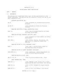
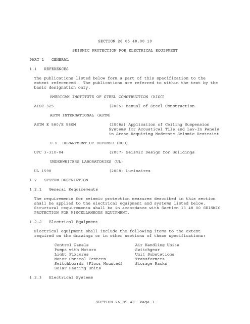
<strong>SECTION</strong> <strong>26</strong> <strong>05</strong> <strong>48</strong>.00 <strong>10</strong>SEISMIC PROTECTION FOR ELECTRICAL EQUIPMENTPART 1GENERAL1.1 REFERENCESThe publications listed below form a part of this specification to theextent referenced. The publications are referred to within the text by thebasic designation only.AMERICAN INSTITUTE OF STEEL CONSTRUCTION (AISC)AISC 325(20<strong>05</strong>) Manual of Steel ConstructionASTM INTERNATIONAL (ASTM)ASTM E 580/E 580M(2008a) Application of Ceiling SuspensionSystems for Acoustical Tile and Lay-In Panelsin Areas Requiring Moderate Seismic RestraintU.S. DEPARTMENT OF DEFENSE (DOD)UFC 3-3<strong>10</strong>-04(2007) Seismic Design for BuildingsUNDERWRITERS LABORATORIES (UL)UL 1598(2008) Luminaires1.2 SYSTEM DESCRIPTION1.2.1 General RequirementsThe requirements for seismic protection measures described in this sectionshall be applied to the electrical equipment and systems listed below.Structural requirements shall be in accordance with Section 13 <strong>48</strong> 00 SEISMICPROTECTION FOR MISCELLANEOUS EQUIPMENT.1.2.2 Electrical EquipmentElectrical equipment shall include the following items to the extentrequired on the drawings or in other sections of these specifications:Control PanelsPumps with MotorsLight FixturesMotor Control CentersSwitchboards (Floor Mounted)Solar Heating UnitsAir Handling UnitsSwitchgearUnit SubstationsTransformersStorage Racks1.2.3 Electrical Systems<strong>SECTION</strong> <strong>26</strong> <strong>05</strong> <strong>48</strong> <strong>Page</strong> 1
Electrical systems shall be installed as required on the drawings and othersections of these specifications and shall be seismically protected inaccordance with this specification.1.2.4 Contractor Designed BracingThe Contractor shall design the bracing in accordance with UFC 3-3<strong>10</strong>-04 andadditional data furnished by the Contracting Officer. Resistance to lateralforces induced by earthquakes shall be accomplished without consideration offriction resulting from gravity loads. UFC 3-3<strong>10</strong>-04 uses parameters for thebuilding, not for the equipment in the building; therefore, correspondingadjustments to the formulas shall be required. Loadings determined usingUFC 3-3<strong>10</strong>-04 are based on strength design; therefore, AISC 325 shall be usedfor the design. The bracing for electrical equipment and systems shall bedeveloped by the Contractor.1.2.5 Conduits Requiring No Special Seismic RestraintsSeismic restraints may be omitted from electrical conduit less than 2-1/2inches trade size. All other interior conduit, shall be seismicallyprotected as specified.1.3 EQUIPMENT REQUIREMENTS1.3.1 Rigidly Mounted EquipmentSpecific items of equipment furnished under this contract shall beconstructed and assembled to withstand the seismic forces specified in UFC3-3<strong>10</strong>-04. Each item of rigid electrical equipment shall be entirely locatedand rigidly attached on one side only of a building expansion joint.Piping, electrical conduit, etc., which cross the expansion joint shall beprovided with flexible joints that are capable of accommodatingdisplacements equal to the full width of the joint in both orthogonaldirections.Engine-GeneratorsSubstationsTransformersSwitch Boards and Switch GearsMotor Control CentersFree Standing Electric Motors1.3.2 Nonrigid or Flexibly-Mounted EquipmentSpecific items of equipment to be furnished as stated in the Delivery orTask Order shall be constructed and assembled to resist a horizontal lateralforce of 0.75 times the operating weight of the equipment at the verticalcenter of gravity of the equipment.1.4 SUBMITTALSGovernment approval is required for submittals with a "G" designation;submittals not having a "G" designation are for information only. Whenused, a designation following the "G" designation identifies the office thatwill review the submittal for the Government. Submit the following inaccordance with Section 01 33 00 SUBMITTAL PROCEDURES:<strong>SECTION</strong> <strong>26</strong> <strong>05</strong> <strong>48</strong> <strong>Page</strong> 2
SD-02 Shop DrawingsLighting Fixtures in Buildings; GEquipment Requirements; GDetail drawings along with catalog cuts, templates, and erectionand installation details, as appropriate, for the items listed.Submittals shall be complete in detail; shall indicate thickness,type, grade, class of metal, and dimensions; and shall showconstruction details, reinforcement, anchorage, and installationwith relation to the building construction. Drawings shall showthe structural or physical features of major equipment items,components, assemblies, and structures, including foundations orother types of supports for equipment and conductors. Thesedrawings shall include accurately scaled or dimensioned outline andarrangement or layout drawings to show the physical size ofequipment and components and the relative arrangement and physicalconnection of related components. Weights of equipment, componentsand assemblies shall be provided when required to verify theadequacy of design and proposed construction of foundations orother types of supports. Dynamic forces shall be stated forswitching devices when such forces must be considered in the designof support structures. The appropriate detail drawings shall showthe provisions for leveling, anchoring, and connecting all itemsduring installation, and shall include any recommendations made bythe manufacturerInclude sway bracing for suspended luminaires.SD-03 Product DataLighting Fixtures in Buildings; GEquipment Requirements; GCopies of the design calculations with the detail drawings.Calculations shall be stamped by a registered engineer and shallverify the capability of structural members to which bracing isattached for carrying the load from the brace.Contractor Designed Bracing; GCopies of the Design Calculations with the Drawings.Calculations shall be approved, certified, stamped and signed by aRegistered Professional Engineer. Calculations shall verify thecapability of structural members to which bracing is attached forcarrying the load from the brace.PART 2PRODUCTS2.1 LIGHTING FIXTURE SUPPORTSLighting fixtures and supports shall conform to UL 1598.2.2 SWAY BRACING MATERIALSSway bracing materials (e.g. rods, plates, rope, angles, etc.) shall be asspecified in Section 13 <strong>48</strong> 00 SEISMIC PROTECTION FOR MISCELLANEOUSEQUIPMENT.<strong>SECTION</strong> <strong>26</strong> <strong>05</strong> <strong>48</strong> <strong>Page</strong> 3
PART 3EXECUTION3.1 SWAY BRACES FOR CONDUITConduit shall be braced as for an equivalent weight pipe in accordance withSection 13 <strong>48</strong> 00.00 <strong>10</strong> SEISMIC PROTECTION FOR MECHANICAL EQUIPMENT.3.2 LIGHTING FIXTURES IN BUILDINGSLighting fixtures and supports shall conform to the following:3.2.1 Pendant FixturesPendant fixtures shall conform to the requirements of UFC 3-3<strong>10</strong>-04.3.2.2 Ceiling Attached Fixtures3.2.2.1 Recessed Fluorescent FixturesRecessed fluorescent individual or continuous-row mounted fixtures shall besupported by a seismic-resistant suspended ceiling support system built inaccordance with ASTM E 580/E 580M or Section 09 51 00 ACOUSTICAL CEILINGS.Seismic protection for the fixtures shall conform to the requirements of UFC3-3<strong>10</strong>-04. Recessed lighting fixtures not over 56 poundsin weight may besupported by and attached directly to the ceiling system runners usingscrews or bolts, number and size as required by the seismic design. Fixtureaccessories, including louvers, diffusers, and lenses shall have lock orscrew attachments.3.2.2.2 Surface-Mounted Fluorescent FixturesSurface-mounted fluorescent individual or continuous-row fixtures shall beattached to a seismic-resistant ceiling support system built in accordancewith ASTM E 580/E 580M or Section 09 51 00 ACOUSTICAL CEILINGS. Seismicprotection for the fixtures shall conform to the requirements of UFC 3-3<strong>10</strong>-04.3.2.3 Assembly Mounted on Outlet BoxA supporting assembly, that is intended to be mounted on an outlet box,shall be designed to accommodate mounting features on 4 inch boxes, plasterrings, and fixture studs.3.2.4 Wall-Mounted Emergency Light UnitAttachments for wall-mounted emergency light units shall be designed andsecured for the worst expected seismic disturbance at the site.3.2.5 Lateral ForceStructural requirements for light fixture bracing shall be in accordancewith Section 13 <strong>48</strong> 00 SEISMIC PROTECTION FOR MISCELLANIOUS EQUIPMENT.-- End of Section --<strong>SECTION</strong> <strong>26</strong> <strong>05</strong> <strong>48</strong> <strong>Page</strong> 4
<strong>SECTION</strong> <strong>26</strong> <strong>05</strong> <strong>48</strong> <strong>Page</strong> 5